Are standard PCB via sizes limiting routing space or leaving too little fabrication margin? Define the finished hole, pad diameter, annular ring, board thickness, and connection depth together. Start with the largest geometry that fits the routing field and passes the selected fabrication process.
The chart below compares standard PCB via sizes in millimeters and mils, then shows how plating, drilling tolerance, current, signal speed, and via type change the final choice. Use it to build early layout rules, but release fabrication data only after checking the stackup and drill table together.

What Are Standard PCB Via Sizes?
A via library must pair the finished hole with its copper pad. Common starting geometries include a 0.30/0.60 mm finished-hole/pad pair for ordinary multilayer routing and 0.20/0.45 mm for tighter layouts. Release either combination only after checking board thickness, copper weight, product class, and the confirmed drill table.
A library rule should store at least the finished hole, pad diameter, plane anti-pad, solder-mask opening, and permitted connection depth. Naming a via only as “0.30 mm” is incomplete because that value could describe the hole, drill tool, or pad.
Standard PCB Via Sizes Chart in mm and Mils
These values are illustrative, not universal IPC limits. These standard PCB via sizes show practical mechanically drilled plated-through-via combinations. Values are rounded because one mil equals 0.0254 mm. The hole column is a finished-hole target; the production drill is normally larger to allow for deposited copper.
| Finished Hole (mm) | Finished Hole (mil) | Pad Diameter (mm) | Pad Diameter (mil) | Ideal Ring Based on Finished Hole |
| 0.20 mm | 7.9 mil | 0.45 mm | 17.7 mil | 0.125 mm / 4.9 mil |
| 0.25 mm | 9.8 mil | 0.55 mm | 21.7 mil | 0.150 mm / 5.9 mil |
| 0.30 mm | 11.8 mil | 0.60 mm | 23.6 mil | 0.150 mm / 5.9 mil |
| 0.40 mm | 15.7 mil | 0.80 mm | 31.5 mil | 0.200 mm / 7.9 mil |
| 0.50 mm | 19.7 mil | 1.00 mm | 39.4 mil | 0.250 mm / 9.8 mil |
These combinations are not acceptance limits. Compare them with the latest capability data, including minimum finished hole, annular ring, drill-to-copper clearance, board thickness, and any special registration allowance.
How Are Standard PCB Via Sizes Measured?
Define the hole and pad separately. The drawing must identify whether a stated via size means the hole or the complete copper pad. The finished hole is the open diameter after plating, while the production drill is normally larger because deposited copper reduces the opening. The pad diameter is the outside copper diameter, while the annular ring is the radial copper width between the finished hole and pad edge.
- Finished hole: The plated opening used in the finished board.
- Tool diameter: The drill chosen before hole-wall copper is deposited.
- Pad diameter: The total copper land surrounding the hole.
- Annular ring: The radial copper width around the hole after registration effects.
For standard PCB via sizes, distinguish an ideal centered ring from the minimum remaining ring after drill offset. The ideal value supports library calculations; the minimum value determines whether the finished feature meets the selected acceptance criteria.
Label every PCB via drill size chart with units, plated status, finished-hole tolerance, and whether each dimension is a nominal tool or finished opening. Apply the same definitions in CAD, NC drill, fabrication drawings, and CAM review.
How Do Standard PCB Via Sizes Compare by Via Type?
Connection depth and drilling method define the via family. A through via crosses the entire board, a blind via connects an outer layer to selected inner layers, and a buried via remains between inner layers. A microvia is a shallow HDI interconnect generally formed by laser processing, historically defined in IPC material as no more than 150 μm in diameter.
| Via Type | Typical Connection | Common Size Direction | Main Control |
| Through via | Top to bottom | Largest mechanical range | Full board aspect ratio |
| Blind via | Outer to inner | Often smaller; stackup-dependent | Controlled depth and registration |
| Buried via | Inner to inner | Stackup-dependent | Sequential lamination plan |
| Microvia | Usually adjacent layers | Up to 0.15 mm under the historical definition | Laser geometry and target-pad interface |
Size alone does not identify the construction. A 0.15 mm feature may be a laser microvia in a thin dielectric or an advanced mechanical hole in a different stackup, and those processes have different aspect-ratio and target-pad controls.
Choose the via family before assigning standard PCB via sizes. Through vias usually offer the simplest fabrication path, while blind, buried, and stacked microvia structures add layer-pair documentation, lamination planning, and interface-reliability checks.
For a deeper classification, review PCB Via Types before choosing a drill method.
What Factors Control Standard PCB Via Sizes?
Choose the largest via that preserves required clearances. Start with stackup depth and available escape space. Then compare standard PCB via sizes against plating, annular ring, drill-to-copper clearance, current path, and signal transition. Also check solder-mask treatment and whether the via will be filled or placed in a component pad.
- Stackup depth: Deeper holes raise the drilling and plating challenge.
- Routing field: Fine-pitch packages may force smaller pads or blind structures.
- Electrical role: Signal, return, power, and thermal paths impose different priorities.
- Fabrication margin: Registration and drill tolerance can reduce the remaining ring.
- Assembly interface: Via-in-pad, exposed holes, and solder wicking may require filling or capping.
Apply these checks to standard PCB via sizes in sequence: confirm the stackup and connection depth, reserve routing space, assign the electrical or thermal role, and then verify fabrication margin. This order prevents a convenient CAD default from becoming an unsupported manufacturing requirement.
How to Calculate Standard PCB Via Sizes and Annular Ring Width?
Calculate the ideal ring first, then add process margin. The basic geometry is simple, but the released pad must also cover drill compensation, positional error, and layer registration.
- Define the hole reference. Confirm whether the drawing specifies a plated finished hole or a production drill-tool diameter. Do not mix the two in one calculation.
- Calculate the centered nominal ring. Use AR = (Pad Diameter − Hole Diameter) ÷ 2. A 0.60 mm pad around a 0.30 mm finished hole gives a 0.15 mm ideal ring.
- Estimate the production drill. The tool is normally larger than the finished opening because barrel copper reduces the hole. The exact compensation belongs to the confirmed fabrication process.
- Check the fabrication ring. Recalculate against the production drill where the CAM rule uses tool size. If a 0.30 mm tool is used with a 0.45 mm pad, the geometric ring before positional allowances is only 0.075 mm.
- Apply tolerance and registration allowances. Subtract drill wander and layer-to-layer misregistration from the ideal condition. Check internal and external lands separately because their acceptance rules may differ.
- Round up to a supported pad. Select the next manufacturable library value when the calculated minimum falls between available rules. Recheck drill-to-copper clearance and routing escape after increasing the pad.
For reverse calculation, use Pad Diameter = Hole Diameter + 2 × Required Ring, then add any supplier-defined fabrication allowance. A PCB via pad size calculator verifies geometry; the drill table and capability review determine whether the result can be released.
How Does Board Thickness Affect Via Size and Aspect Ratio?
Board thickness directly affects via aspect ratio. A thicker connection depth generally requires a larger hole because copper must plate uniformly along a longer barrel. Via aspect ratio is commonly expressed as connection depth divided by hole or drill diameter, using the fabricator’s stated convention. For a 1.60 mm through connection and a 0.30 mm hole, the simple ratio is about 5.3:1.
The same 0.30 mm hole becomes more demanding on a 2.40 mm board at about 8:1. Blind vias use the actual layer-to-layer depth rather than full board thickness. Confirm whether the capability limit uses drilled or finished diameter before comparing values.
Aspect ratio influences desmear access, activation, and copper distribution along the barrel. For standard PCB via sizes near a process limit, increasing the hole, reducing connection depth, or changing the via structure usually provides more robust margin than relying on a nominal maximum.
Match every PCB via aspect ratio chart to the supplier’s drilled- or finished-diameter convention. Record that convention beside the limit so reviewers calculate the same ratio.
What Is the Minimum Practical Via Size for PCB Manufacturing?
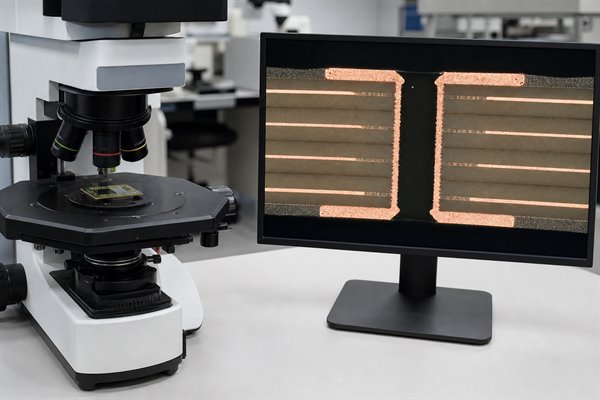
A 0.25 or 0.30 mm hole often provides better process margin. A 0.20 mm finished mechanical hole may be available, but its suitability depends on stackup depth, drilling, plating, and registration capability. Smaller geometry also affects tool life, panel loading, and inspection controls.
Do not select a minimum hole from a generic chart alone. Check the finished-hole range, tool increment, annular ring, aspect ratio, copper thickness, and the distinction between prototype and volume capability. The related PCB drill sizes guide explains why tool and finished dimensions differ.
For volume production, standard PCB via sizes must remain repeatable across the intended quantity, material system, panel format, and inspection plan. A prototype capability may be technically possible but unsuitable as the default production rule.
If routing allows, moving from a 0.20 mm hole to 0.25 or 0.30 mm can improve drill life, plating access, and registration margin. Use the smaller option where it solves a specific density problem rather than as an automatic board-wide choice.
How to Choose Via Sizes for Signal, Power and Thermal Vias?
Via function determines the sizing priority. Signal transitions emphasize geometry and return paths, while power and thermal structures emphasize parallel copper area, temperature rise, and heat spreading.
- Ordinary signal vias: Start with a repeatable mechanical size that preserves annular ring and routing clearance. Keep the library uniform unless escape routing or electrical performance justifies another family.
- Power vias: Evaluate the finished barrel diameter, plated copper thickness, allowable temperature rise, connected plane area, and the number of vias in parallel. Do not assign current capacity from drill diameter alone.
- Thermal vias: Use an array to connect the heat source to useful copper on other layers. Balance hole size, pitch, copper spreading area, board thickness, solder-mask treatment, and assembly behavior.
- Return-path vias: Place ground transitions close to signal layer changes so return current does not take a wide detour. The spacing should follow the interface frequency and field-solver or layout review.
- Via-in-pad structures: Confirm filling, planarization, and copper capping when the via sits inside a solderable land. An open via can wick solder and reduce joint consistency.
Use several vias when parallel paths improve current distribution or thermal transfer, but preserve enough copper between holes. Final quantity should come from electrical and thermal analysis plus the fabricator’s minimum hole spacing.
How to Select Via Sizes for High-Speed PCBs?
Treat a high-speed via as a complete transition. Hole and pad size affect the result, but barrel length, unused stub, anti-pad, reference planes, and nearby return vias usually matter just as much.
- Start with the real stackup: Use actual dielectric thicknesses, copper layers, finished board thickness, and the layers connected by the via. A generic 2D rule cannot represent the transition correctly.
- Control pad capacitance: A smaller pad can reduce local capacitance, but it also reduces registration margin. Adjust the pad and plane anti-pad together rather than shrinking one feature in isolation.
- Limit unused barrel: A long open stub can create resonant behavior. Consider blind vias or backdrilling when simulation shows that the stub affects the required data rate or insertion-loss budget.
- Preserve the return path: Add nearby ground vias when a signal changes reference planes. Keep them close enough to limit the return-loop area without violating spacing or anti-pad rules.
- Review differential symmetry: Match via count, pad geometry, anti-pads, reference transitions, and breakout routing for both members of a differential pair.
- Validate the launch: Model the package or connector breakout with the via transition. Confirm impedance, reflection, crosstalk, and loss before freezing the drill library.
Do 2-Layer, 4-Layer and Multilayer PCBs Require Different Via Sizes?
Layer count alone does not set via diameter. Board thickness, plane arrangement, routing density, and connection depth often change the result. A 2-layer and 4-layer board can share the same 0.30/0.60 mm rule when thickness and clearances match. A dense multilayer board may require smaller pads, blind vias, or backdrilling even when the finished through-hole remains unchanged.
- Two-layer boards: Thickness and copper clearance usually control the rule because there are no internal plane anti-pads or buried connections.
- Four-layer boards: The same hole may remain practical, but internal plane clearances and return-path transitions require review.
- Higher-layer-count boards: Increased thickness, dense escape routing, multiple reference planes, and sequential structures can justify smaller pads, backdrilling, or blind vias.
Do not shrink the through-hole merely because the board has more layers. First determine whether the real constraint is aspect ratio, anti-pad congestion, BGA escape, unused stub length, or a local connection that does not require the full board depth.
What Do IPC Standards Say About PCB Via Sizes?
IPC does not mandate one universal via diameter. Its documents define design principles, product classes, qualification, performance, and acceptance criteria. Standard PCB via sizes must still match the selected construction. IPC-2221 supports generic board design, the IPC-6012 family addresses rigid-board performance, and HDI structures require applicable sectional guidance and purchasing specifications.
State the required product class and acceptance criteria on the fabrication documentation. Also verify the revision, amendments, and contractual hierarchy in force for the order. A preferred library value does not replace the finished-board acceptance requirements.
Use IPC documents for design principles and acceptance language, then apply approved supplier limits for drills, pads, and aspect ratios. Do not specify an “IPC standard PCB via size” without the stackup, product class, and manufacturing process.
For HDI structures, document the layer pair, dielectric depth, target pad, stacking or staggering method, fill requirement, and qualification evidence. These details carry more engineering value than quoting a microvia diameter by itself.
How Do Drilling and Plating Tolerances Affect Finished Via Size?
Plating makes the finished opening smaller than the drilled hole. The drill tool creates the initial opening before copper is deposited on the barrel. Tool wear, spindle position, material movement, layer registration, desmear, and copper distribution influence the final geometry. Consequently, the fabrication drawing should distinguish plated finished holes from drill-tool data and identify tolerances clearly.
Pad size must preserve acceptable copper after these variations. A nominal 0.15 mm geometric ring can become smaller at the finished board when the hole shifts toward one pad edge, so production allowance cannot be removed from the calculation.
Build the tolerance chain for standard PCB via sizes from the production drill, expected plating reduction, finished-hole tolerance, drill position, and layer registration. The worst-case condition is not the centered nominal ring shown in a CAD library.
Specify the required finished opening where component fit or pin insertion matters. For ordinary vias, confirm the supplier’s standard finished-hole tolerance and avoid imposing a tighter tolerance unless the function supports it.
What Via Size Problems Can Reduce PCB Reliability?
Small holes in thick boards increase plating and thermal risk. Geometry outside proven drilling, cleaning, plating, registration, or thermal-cycling limits can cause ring loss, partial breakout, uneven barrel copper, resin smear, voids, barrel cracks, pad lifting, and weak microvia target interfaces.
- Ring loss: Drill offset leaves too little copper around the finished hole.
- Barrel weakness: Poor hole preparation or plating distribution raises crack and open-circuit risk.
- Thermal stress: Z-axis expansion loads the copper barrel during assembly and service cycles.
- Microvia interface failure: Stacked structures require controlled construction and suitable performance evidence.
Match each risk to evidence. Cross-sections can reveal barrel copper, voids, smear removal, and internal connections; electrical testing verifies net continuity; thermal-stress coupons can expose latent interconnect weakness under the specified acceptance plan.
Do not treat a visually centered surface pad as proof that every internal layer has adequate copper. Internal registration and pad breakout require the applicable inspection method and acceptance criteria.
PCB Via Size Selection Example for a Multilayer Board
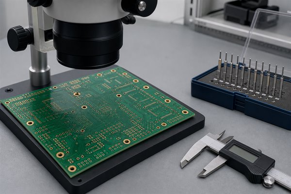
Begin with a manufacturable baseline. Consider a 1.60 mm, six-layer control board with ordinary signal routing, power planes, and one fine-pitch device. Start the general through-via library at a 0.30 mm finished hole with a 0.60 mm pad.
The centered nominal ring is 0.15 mm, and the simple finished-hole aspect ratio is about 5.3:1. These figures are screening values. CAM must still check the production drill, internal lands, registration allowance, copper weight, and plane anti-pads.
Use the baseline via for unrestricted signal transitions and suitable ground returns. Review power and thermal locations separately because their via count, connected copper, temperature rise, and assembly conditions differ from ordinary signal routing.
If the 0.60 mm pad blocks escape channels under the fine-pitch device, do not shrink every via on the board. Evaluate a local 0.20/0.45 mm mechanical rule only after capability confirmation, or use an HDI PCB fabrication structure where the stackup supports laser microvias.
Release the design only after the drill table identifies finished versus tool diameters and every via family passes annular-ring, aspect-ratio, clearance, electrical, thermal, and filling checks.
How Can We Optimize Via Sizes Before PCB Manufacturing?
Optimize vias before releasing fabrication data. Remove duplicate drill families, recover routing space where required, and keep every critical via inside the confirmed process window.
- Freeze the stackup: Record finished thickness, copper weights, dielectric depths, sequential laminations, and the actual connection depth of each blind or buried structure.
- Classify via functions: Separate ordinary signal, return, power, thermal, high-speed, blind, buried, microvia, backdrilled, and via-in-pad requirements.
- Normalize the drill library: Reuse practical hole-and-pad pairs where their electrical and physical roles match. Remove duplicate sizes that create tooling complexity without adding value.
- Run geometric checks: Calculate ideal ring, production-drill ring, aspect ratio, drill-to-copper clearance, hole spacing, anti-pad clearance, and board-edge distance.
- Review special treatments: Confirm tenting, plugging, resin filling, planarization, copper capping, and backdrilling before they become quotation or assembly surprises.
- Validate electrical and thermal roles: Check current sharing, temperature rise, heat spreading, return continuity, differential symmetry, stub length, and modeled transition performance where applicable.
- Complete fabrication DFM: Compare the drill table and stackup with confirmed tolerances, registration capability, plating process, inspection method, and acceptance class.
Send Gerber or ODB++, NC drill data, stackup, copper requirements, hole tolerances, impedance information, and special-via notes as one controlled package. Cross-check the drawing, drill file, netlist, and quotation notes so they describe the same geometry and treatment.
FAQs About Standard PCB Via Sizes
Q1: Why can a filled via develop a surface dimple?
A1: Resin shrinkage or incomplete planarization can leave a depression. Specify fill, cure, planarization, and copper-cap acceptance when surface flatness affects an assembly pad.
Q2: Should nonfunctional internal pads be removed?
A2: Removal can improve clearance, but it changes mechanical and electrical behavior. Decide by stackup, reliability class, signal performance, and the fabricator’s approved practice.
Q3: When are teardrops useful at via connections?
A3: Teardrops add copper where a narrow trace enters a pad. They can improve tolerance to registration or etching variation when permitted by the layout and acceptance rules.
Q4: How close can a via be placed to a routed board edge?
A4: The limit depends on finished edge tolerance and required copper clearance. Measure from the relevant copper or drilled feature and include routing movement, plating exposure, and any edge-metal requirement.
Q5: Can solder mask cover only one side of a via?
A5: Yes, asymmetric mask treatment is possible when clearly documented. Confirm whether the intent is tenting, partial plugging, test access, or solder-flow control.
Q6: Why do thermal-pad vias sometimes wick solder?
A6: An open barrel provides a path for molten solder. Hole size, stencil design, mask treatment, fill method, and reflow conditions determine whether wicking becomes significant.
Q7: Can a plated via be placed in a flex bend area?
A7: Avoid it unless the rigid-flex construction specifically supports it. A plated barrel concentrates strain and may crack during repeated bending, so keep vias in supported rigid regions where possible.
Q8: How should blind and buried vias appear in fabrication data?
A8: Separate drill files should identify each layer pair or controlled depth. The stackup drawing must agree with those files and show the required lamination sequence.
Q9: Are vias included in bare-board electrical testing?
A9: Vias are normally part of the tested net connectivity. Confirm the test method, coverage, and special coupon requirements when intermittent barrel or microvia reliability is a concern.
Q10: What causes copper-cap cracking over a filled via?
A10: Fill voids, material mismatch, or thermal stress can damage the cap. Control hole preparation, fill quality, cure, planarization, cap plating, and thermal acceptance criteria.
Conclusion
Match the full via geometry to the stackup and process. Verify standard PCB via sizes by checking the hole, pad, annular ring, connection depth, and fabrication tolerance for each signal, power, thermal, blind, buried, or microvia structure.
EBest provides custom PCB production support for prototypes and volume orders. Send Gerber/ODB++, NC drill files, stackup, copper requirements, quantity, and special via notes to sales@bestpcbs.com for a manufacturability review and quotation.
You may also like







Tags: PCB Via Annular Ring, PCB Via Design Rules, PCB Via Drill Sizes, PCB Via Sizes