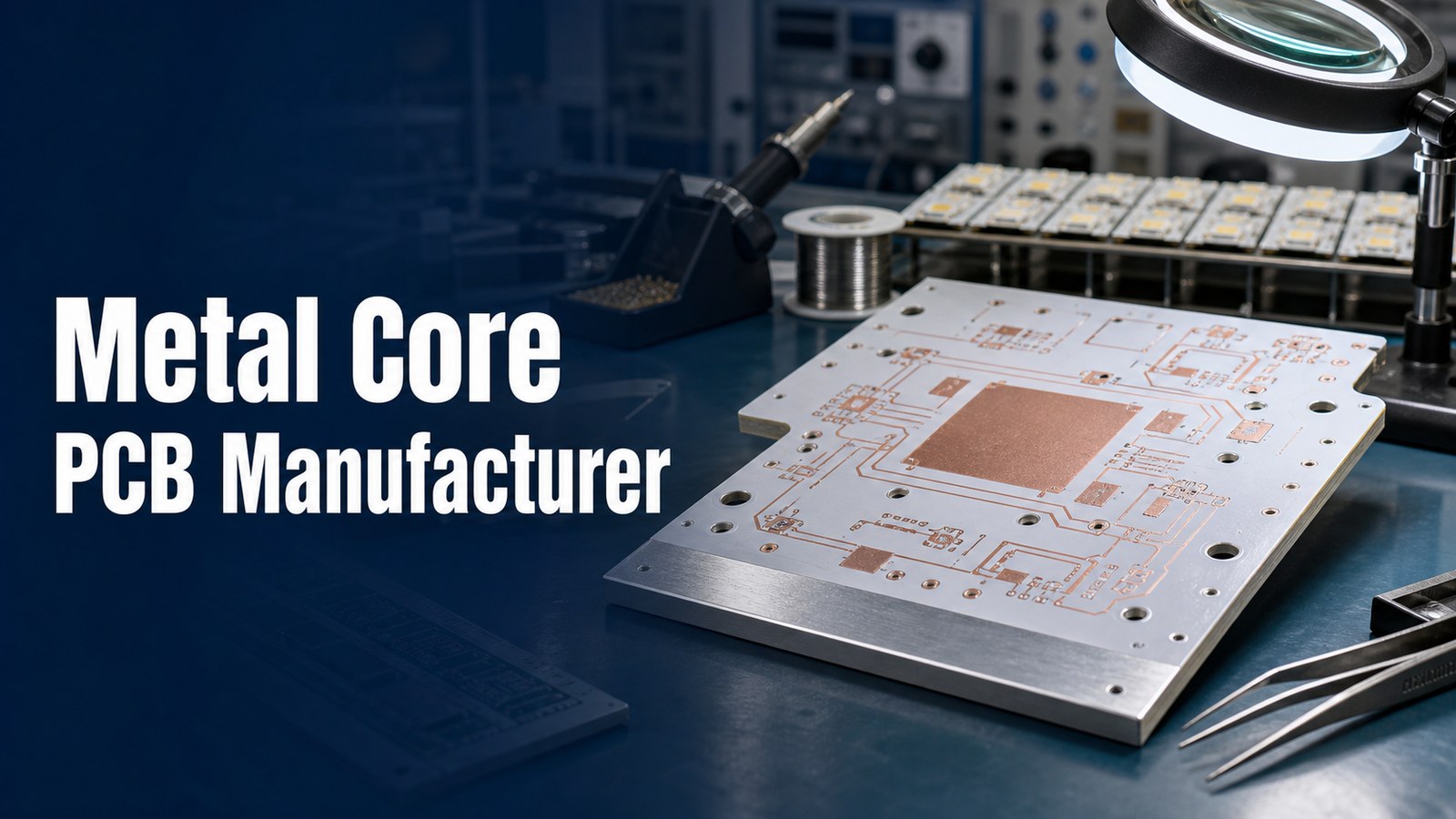
A metal core PCB manufacturer should help you control base material, dielectric performance, copper thickness, heat flow, DFM risk, assembly fit, testing scope and quote details before fabrication starts. Metal core PCB projects are usually chosen because heat cannot be treated as a secondary issue. If the board supports LEDs, power modules, motor controls, converters, industrial electronics or compact thermal assemblies, the manufacturing review must connect the circuit design with the real heat path.
EBest Circuit supports metal core PCB buyers with metal core PCB manufacturing capabilities, file review, MCPCB material discussion, DFM feedback, optional PCBA coordination and RFQ planning. Send Gerber or ODB++, stackup notes, drawings, quantity, copper, surface finish, thermal requirements and assembly files early so the quote can be reviewed as a heat-critical build instead of a generic circuit board.
What Should a Metal Core PCB Manufacturer Help You Control?
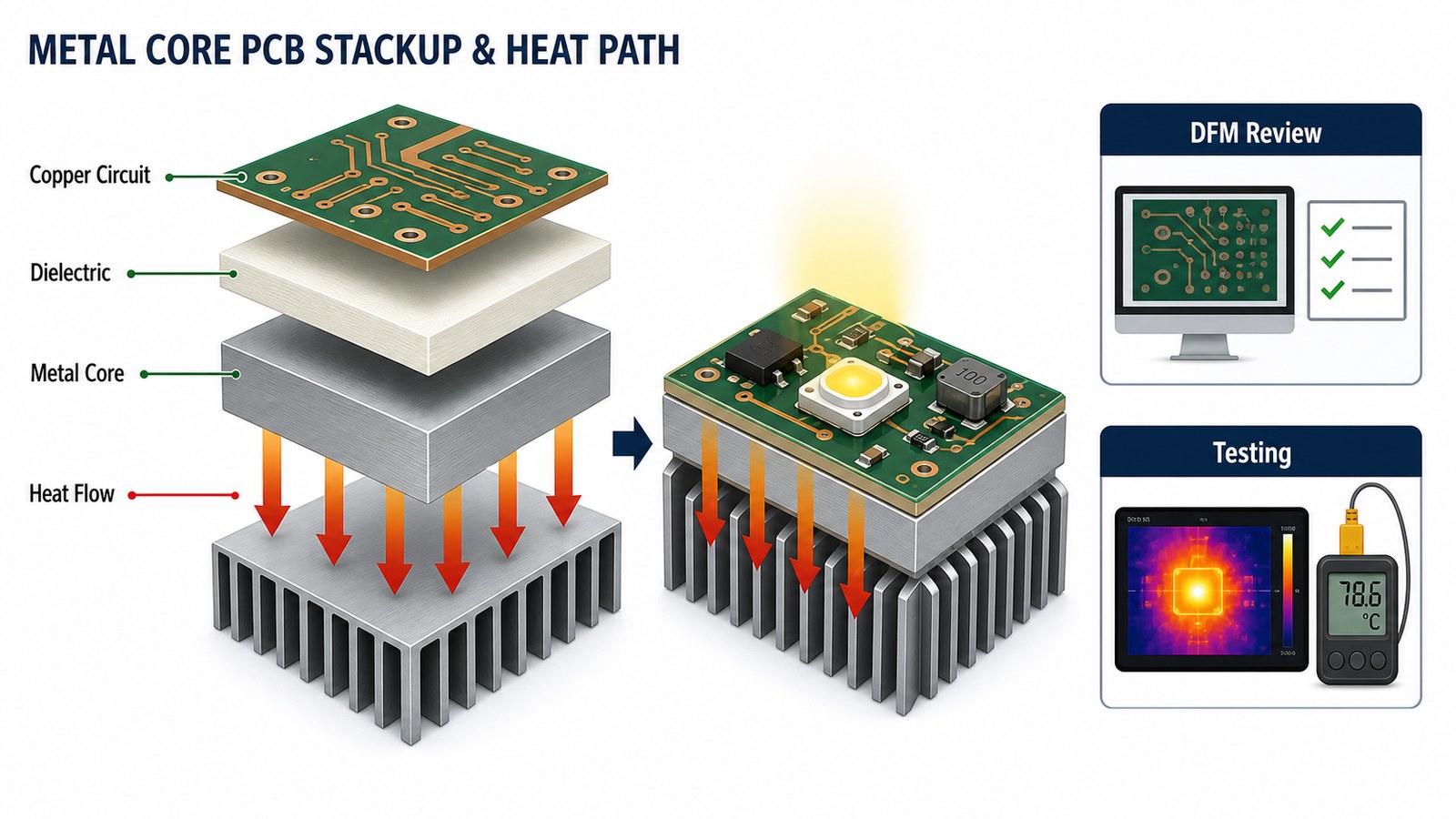
A metal core PCB manufacturer should help control the thermal path, manufacturability and quotation scope of the board, not only the bare PCB price. A metal core PCB places an aluminum, copper or other metal base under the circuit structure so heat can move away from hot components more efficiently than on a normal FR4-only board.
The buyer’s main decision is not simply whether the board is called MCPCB, IMS PCB, aluminum PCB or metal-backed PCB. The practical questions are: which metal base is suitable, what dielectric is required, how much copper is needed, whether the stackup can be fabricated, how the board will be assembled, and how the finished build will be tested.
Is your metal core PCB quote risky because the heat path is not fully defined?
Metal core PCB projects often lose time before the first order because the RFQ package does not make the manufacturing risk visible enough:
- The drawing names aluminum or copper core, but the dielectric, thermal conductivity target or final board thickness is not clear.
- LED or power components create concentrated heat, yet the PCB files do not show how the heat should move through the board and mounting structure.
- Copper thickness, hole size, line/space, solder mask bridge or surface finish expectations are copied from a standard PCB quote without MCPCB review.
- The buyer asks for fast pricing, but the supplier cannot explain which values are standard, which need material confirmation and which need engineering review.
- Assembly, test access and thermal inspection are discussed after fabrication, when layout and panel decisions are already harder to change.
Where Metal Core PCB Buyers Usually Lose Time Before Quotation
Metal core PCB buyers usually lose time when the supplier cannot separate standard manufacturing items from project-dependent thermal and material decisions. A fast quote is useful only when the manufacturing assumptions are correct. Otherwise, the first price can hide dielectric changes, copper changes, tooling review, thermal testing needs or assembly constraints.
For many teams, the first slowdown happens because the files describe the circuit, but not the thermal target. The next slowdown comes when the PCB quote and PCBA quote are handled separately. If the board will carry high-power LEDs or power devices, the bare board, mounting plan, soldering process and final test method should be reviewed together.
EBest Circuit helps buyers make metal core PCB risk visible before fabrication:
- We review Gerber or ODB++ files together with stackup notes, base metal, dielectric, copper, surface finish, board thickness and drawing requirements.
- We help identify whether aluminum, copper or stainless steel base material is a better starting point for the application and quote target.
- We connect MCPCB fabrication review with PCBA support when BOM, CPL, LED orientation, soldering and test access affect the manufacturing result.
- We keep special values as review items instead of turning them into unsupported promises when material sourcing or factory routing must be confirmed.
- We help buyers compare quote scope, not only price, so the chosen supplier can support prototype, low-volume and repeat builds more predictably.
How EBest Circuit Reviews Metal Core PCB Projects Before Fabrication
EBest Circuit reviews metal core PCB projects by checking the thermal structure and manufacturing route before the buyer commits to fabrication. Our review starts with the file package, then checks base material, dielectric, copper, line/space, holes, solder mask, surface finish, routing, assembly files and test expectations.
This matters because metal core boards can look simple from the top copper layer, while the manufacturing risk sits inside the base material, insulation layer and heat-transfer path. When a value depends on the original files, material availability or special process route, we confirm it as part of the project review instead of writing it as a blanket claim.
Is a Metal Core PCB the Right Fit for Your Board?
A metal core PCB is a good fit when the board must move heat away from components more efficiently than a standard FR4 board can support. Common use cases include LED lighting, power supplies, automotive lighting modules, motor drives, industrial controls, converters, battery systems, RF power devices and compact electronics with concentrated heat sources.
| Project Situation | Why Metal Core Helps | RFQ Question to Ask |
|---|---|---|
| High-power LED board | Moves heat away from LED packages and solder joints | What dielectric and base metal should support the thermal target? |
| Power electronics module | Improves heat spreading under switching or power devices | Does copper thickness, finish and assembly route match the load? |
| Compact thermal design | Reduces dependence on board area alone for heat control | How will the PCB connect to enclosure, heat sink or mounting surface? |
| Prototype moving to production | Creates a clearer thermal manufacturing baseline | Which values are standard and which need production confirmation? |
Metal Core PCB Materials: Aluminum, Copper and Stainless Steel
Metal core PCB material selection should match the heat path, mechanical needs, cost target and fabrication route. EBest Circuit’s verified MCPCB capability source lists aluminum, copper and stainless steel as base material options. Aluminum is common for many LED and industrial thermal boards. Copper can be considered when higher heat spreading is required. Stainless steel is more application-specific and should be reviewed against the actual design.
Material naming alone is not enough for a good quote. Include the base metal, base material thickness, final board thickness, dielectric target, copper thickness, surface finish and mechanical drawing when you send the RFQ. If you are not sure which metal base is best, send the use case and thermal concern so the quote can start from a realistic structure.
Layer Count, Thickness, Copper and Line/Space Capability
Metal core PCB capability should be checked against the actual stackup because layer count, copper and thickness can change the manufacturing path. EBest Circuit’s verified MCPCB capability sheet lists 1-10 layers, 0.6 mm minimum board thickness, 4.0 mm maximum board thickness, 0.5 oz to 10 oz copper, 4/4 mil line/space, 8 mil minimum solder mask bridge and 10 mil minimum hole diameter.
| Capability Area | Verified Reference | Buyer Note |
|---|---|---|
| Base materials | Aluminum, copper, stainless steel | Confirm against heat, cost and mechanical requirements |
| Layers | 1-10 layers | Send stackup for multilayer MCPCB review |
| Board thickness | 0.6 mm to 4.0 mm in MCPCB sheet | Some thicker material routes require confirmation |
| Copper thickness | 0.5 oz to 10 oz in MCPCB sheet | Heavy copper and fine features should be reviewed together |
| Line/space | 4/4 mil (0.10/0.10 mm) | Actual approval depends on copper, layout and process route |
| Surface treatment | ENIG, ENEPIG, OSP, lead-free HASL | Choose by soldering, shelf life and assembly needs |
Dielectric and Thermal Conductivity Choices
The dielectric layer is one of the most important MCPCB quote decisions because it separates the circuit from the metal base while controlling heat transfer. EBest Circuit’s verified MCPCB capability sheet lists thermal conductivity examples of 1 W, 1.5 W, 2 W and 3 W. Higher thermal-conductivity material routes can be possible in some cases, but they require material and project confirmation.
For buyers, the best question is not “what is the highest number you can quote?” The better question is whether the dielectric, copper, base metal, soldering process and final mechanical assembly can meet the product’s thermal need at a controlled cost. A 3 W material may not automatically solve a poor heat path, and a lower thermal-conductivity material may still work when the layout, mounting and heat sink are well designed.
Metal Core PCB Manufacturing Process
The metal core PCB manufacturing process should be planned around stackup, insulation, copper patterning, drilling, surface finish, routing and inspection. A typical process starts with file intake and engineering review, then moves through material confirmation, imaging, etching, drilling, plating where applicable, solder mask, surface finish, profiling, electrical test and final inspection.
Metal core boards need special attention because the metal base affects drilling, routing, thermal behavior and handling. For double-sided, multilayer or thermally separated structures, the process route must be checked more carefully than a simple single-sided aluminum LED board.
DFM Checks Before MCPCB Fabrication
DFM review before MCPCB fabrication should check whether the design can be built, assembled, mounted and tested without avoidable thermal or manufacturing risk. Key review points include base metal, dielectric target, copper weight, line/space, hole size, solder mask bridge, surface finish, board outline, mounting holes, panelization, component heat sources and inspection method.
EBest Circuit’s process evidence shows why review language matters. Some values are standard; others depend on copper thickness, ordered material, special process route or factory confirmation. A good manufacturer should state this clearly before quoting so the buyer understands what is firm and what needs engineering confirmation.
Metal Core PCB Assembly and PCBA Support
Metal core PCB assembly should be planned with the thermal board from the beginning because component placement, soldering and test access can affect the final result. High-power LEDs, power packages, connectors and thermal interface points should be reviewed together with BOM, CPL, assembly drawing, polarity, package size and test requirements.
If your project needs turnkey support, EBest Circuit can connect metal core PCB fabrication with PCBA manufacturing and prototype PCB assembly planning. This helps avoid a common problem: the bare board is quoted first, but the soldering and final test assumptions are discovered too late.
Testing and Quality Checks for Heat-Critical Boards
Testing for heat-critical metal core boards should confirm both electrical function and manufacturing consistency. Depending on the project, checks may include electrical test, visual inspection, dimensional inspection, solderability review, thermal inspection, assembly inspection and project-specific documentation.
For LED and power electronics, test planning should be realistic. Ask what is included in the PCB quote, what belongs to assembly inspection, and whether any thermal or functional test needs a special fixture. A quote that ignores testing can look cheaper but create risk later.
What Determines Metal Core PCB Cost?
Metal core PCB cost is driven by material, dielectric, copper, board size, thickness, layer count, surface finish, inspection and assembly scope. The cheapest quote is not always the lowest-cost build if it leaves out thermal review, PCBA planning or test requirements.
| Cost Driver | Why It Matters | RFQ Control Point |
|---|---|---|
| Base material | Aluminum, copper and stainless steel have different cost and use cases | State the preferred base metal or describe the thermal requirement |
| Dielectric | Thermal conductivity and insulation affect performance and material cost | Provide target thermal conductivity or ask for review |
| Copper and geometry | Heavy copper, fine spacing and small holes change fabrication risk | Send finished copper, line/space and drill requirements |
| Surface finish | Finish affects solderability, shelf life and assembly path | Choose ENIG, OSP, ENEPIG or lead-free HASL based on assembly needs |
| PCBA and test | Assembly and testing can change total project cost more than bare PCB price | Send BOM, CPL, assembly drawing and test plan with the PCB RFQ |
How to Compare Metal Core PCB Suppliers
Compare metal core PCB suppliers by engineering review depth, thermal manufacturing fit and quote scope, not only by online unit price. A useful supplier should explain which requirements are standard, which are project-dependent, and what must be confirmed before production.
| Check Item | What to Ask | Why It Matters |
|---|---|---|
| Thermal review | Can they review base metal, dielectric and heat path before quote? | MCPCB success depends on thermal structure, not only copper traces |
| Capability clarity | Do they separate standard capability from values needing confirmation? | It prevents unsupported assumptions from entering the purchase order |
| PCBA support | Can they review BOM, CPL, LED orientation and test access? | Thermal PCB risk often continues into assembly |
| Testing scope | What inspection and test items are included? | Quotes are not comparable unless test scope is clear |
| Production planning | Can they support prototype, low-volume and repeat builds? | The first build should not create a dead end for production |
RFQ Checklist for a Metal Core PCB Manufacturer
A complete metal core PCB RFQ package should let the manufacturer review the board as a thermal product from the first message. Send these items when available:
- Gerber or ODB++ files.
- Fabrication drawing and board outline.
- Base material preference: aluminum, copper, stainless steel or open for review.
- Dielectric target or thermal conductivity requirement.
- Layer count, final thickness, copper thickness and surface finish.
- Quantity for prototype, low-volume or production order.
- BOM, CPL, assembly drawing and test plan for PCBA projects.
- Heat sink, enclosure, mounting, screw hole or mechanical interface notes.
- Inspection, documentation, packaging and target delivery requirements.
Why Put EBest Circuit on Your MCPCB Quote List?
EBest Circuit is worth adding early to your metal core PCB quote list because thermal PCB sourcing works best when manufacturing, DFM, PCBA and cost control are reviewed together. We directly serve overseas buyers who need responsive engineering communication, stable quality, practical cost control, PCBA coordination and clear production planning for non-sensitive industrial, communication, LED, medical electronics, consumer electronics and small-to-medium batch projects.
Our advantage is not just that we can quote an MCPCB. The stronger reason to include EBest Circuit is that we can help you check the board before the quote becomes a purchase mistake. If your current supplier only prices the Gerber files, send the same package to us and compare the review depth, questions, manufacturing route and total project scope. For related thermal board planning, you can also read our aluminum PCB manufacturer guide and prototype PCB manufacturing RFQ guide.
FAQ About Metal Core PCB Manufacturers
What is a metal core PCB manufacturer?
A metal core PCB manufacturer fabricates circuit boards that use a metal base such as aluminum, copper or stainless steel to improve heat transfer from components. The manufacturer should review base material, dielectric, copper, surface finish, DFM risk, assembly needs and testing before quotation.
Is a metal core PCB the same as an aluminum PCB?
An aluminum PCB is one common type of metal core PCB, but not every metal core PCB uses aluminum. Metal core boards can also use copper or stainless steel depending on the project. The correct choice depends on heat flow, mechanical needs, cost and manufacturing route.
What files are needed for a metal core PCB quote?
Send Gerber or ODB++, fabrication drawing, stackup notes, base metal preference, dielectric target, copper thickness, surface finish, quantity and delivery target. For assembly, also send BOM, CPL, assembly drawing and test requirements.
Does a higher thermal conductivity dielectric always make the board better?
No. Higher thermal conductivity can help, but the full heat path matters. Copper layout, base metal, dielectric thickness, mounting method, heat sink contact, component placement and assembly quality also affect thermal performance.
Can EBest Circuit support metal core PCB assembly?
Yes. EBest Circuit can connect metal core PCB fabrication with PCBA support when the project needs BOM review, CPL checking, SMT assembly, test planning and production coordination. Send the assembly files together with the PCB files for a more complete review.
Final Recommendation
Choose a metal core PCB manufacturer that reviews the thermal structure before quoting, not one that only returns the fastest unit price. For heat-critical electronics, the right quote must match the base material, dielectric, copper, surface finish, assembly plan and inspection scope.
If you are preparing a metal core PCB or MCPCB assembly project, send your Gerber or ODB++ files, stackup notes, fabrication drawing, BOM, CPL, quantity, base material preference, dielectric or thermal target, copper thickness, surface finish, testing requirements and target schedule to sales@bestpcbs.com. EBest Circuit will review the files and help you build a clearer metal core PCB manufacturing quotation path.
You may also like


Tags: Metal Core PCB, pcb manufacturing, PCB Quote