

A rigid PCB 5V addressable RGB strip is a straight or shaped FR4 LED module where each RGB pixel can be controlled individually through a digital data signal. It is a better choice than a flexible LED strip when the product needs mechanical stability, predictable solder quality, stronger connector retention, or a custom board shape for an OEM lighting assembly.
The biggest engineering risks are not the RGB effect itself. The real risks are voltage drop, copper width, LED current, data signal integrity, heat, connector rating, and whether the supplier can test every pixel before shipment.
Quick Answer: When Should You Use This Type of LED PCB?
Use a rigid PCB 5V addressable RGB strip when you need individually controlled RGB pixels on a stable board that can be mounted, screwed, snapped, or assembled into a product repeatedly.
| Decision Point | Rigid PCB 5V Addressable RGB Strip Fits When | Watch Out For | Buyer or Engineering Note |
|---|---|---|---|
| Product structure | The LED module is fixed inside a housing, display, fixture, machine, or sign. | Do not use rigid PCB where the strip must bend after assembly. | Confirm screw holes, edge clearance, and connector location early. |
| Control method | Each LED or pixel group needs individual color control. | Some LEDs have strict timing and reset requirements. | Match the controller firmware to the LED IC, such as WS2812B or SK6812. |
| Power | The system already uses 5V DC or has a reliable 5V regulator. | Long strips can suffer voltage drop and color shift. | Plan power injection pads and wide 5V/GND copper. |
| Manufacturing | You need repeatable SMT assembly and full pixel testing. | Poor reflow control can damage LEDs or create color inconsistency. | Ask for optical and electrical test records. |
| Customization | You need custom length, pitch, mounting holes, connectors, or shape. | Small design changes affect panelization and cost. | Provide mechanical drawings together with Gerber and BOM files. |
What Makes It Different from a Flexible Addressable LED Strip?
A rigid PCB strip uses a hard board material, commonly FR4, instead of a bendable flexible circuit. This changes mechanical performance, solder joint stability, mounting options, and heat spreading.
| Item | Rigid PCB Addressable RGB Strip | Flexible Addressable RGB Strip | Practical Difference |
|---|---|---|---|
| Mechanical behavior | Stable and non-bending | Bendable and easy to route around curves | Rigid PCB is better for repeatable mounting and fixture integration. |
| Assembly stability | Good SMT support and flatness | Can be affected by flex handling and adhesive backing | Rigid board is easier to fixture during production testing. |
| Connector strength | Better for terminal blocks, board-to-wire, or board-to-board connectors | Often uses solder pads or light-duty connectors | Important for OEM products with repeated assembly. |
| Thermal path | Can use wider copper and mounting contact to a housing | Depends heavily on flex copper and installation surface | Rigid PCB may be easier to cool in enclosed products. |
| Custom shape | Can be routed, slotted, drilled, or made into modular sections | Better for long continuous curved paths | Choose based on mechanical design, not only LED type. |
Common Related LED and PCB Options
Most buyers comparing this product also compare LED IC type, voltage, board material, pixel density, and connector style. The table below helps avoid mixing terms that sound similar but lead to different designs.
| Item / Related Term | What It Means | When It Applies | How It Differs | Buyer or Engineering Note |
|---|---|---|---|---|
| WS2812B RGB strip | Common 5V addressable RGB LED with integrated control circuit | Decorative lighting, indicators, small displays, OEM modules | One data line controls chained pixels | Check timing, data direction, and maximum current during full white. |
| SK6812 RGB or RGBW strip | Addressable LED family often used for RGB or RGBW lighting | Projects needing RGBW or alternate package options | Firmware settings may differ from WS2812B | Confirm RGB/RGBW order before production. |
| 5V addressable LED strip | Low-voltage strip where pixels are digitally controlled | Short runs, controller-driven effects, individual pixel control | Higher current than 12V or 24V for the same power | Plan power injection for long or high-density layouts. |
| 12V addressable strip | Higher-voltage addressable lighting option | Longer wiring runs or lower current distribution | May use grouped pixels or different driver design | Check whether every LED is individually addressable. |
| Rigid FR4 LED PCB | Hard PCB substrate used for LED mounting | OEM modules, panels, fixtures, displays, machine lighting | Stronger but not bendable | Specify thickness, copper weight, solder mask color, and mounting holes. |
| Aluminum LED PCB | Metal-core PCB for better thermal performance | Higher power or heat-sensitive lighting modules | Different cost, drilling, insulation, and routing constraints | Use when heat is a stronger concern than routing complexity. |
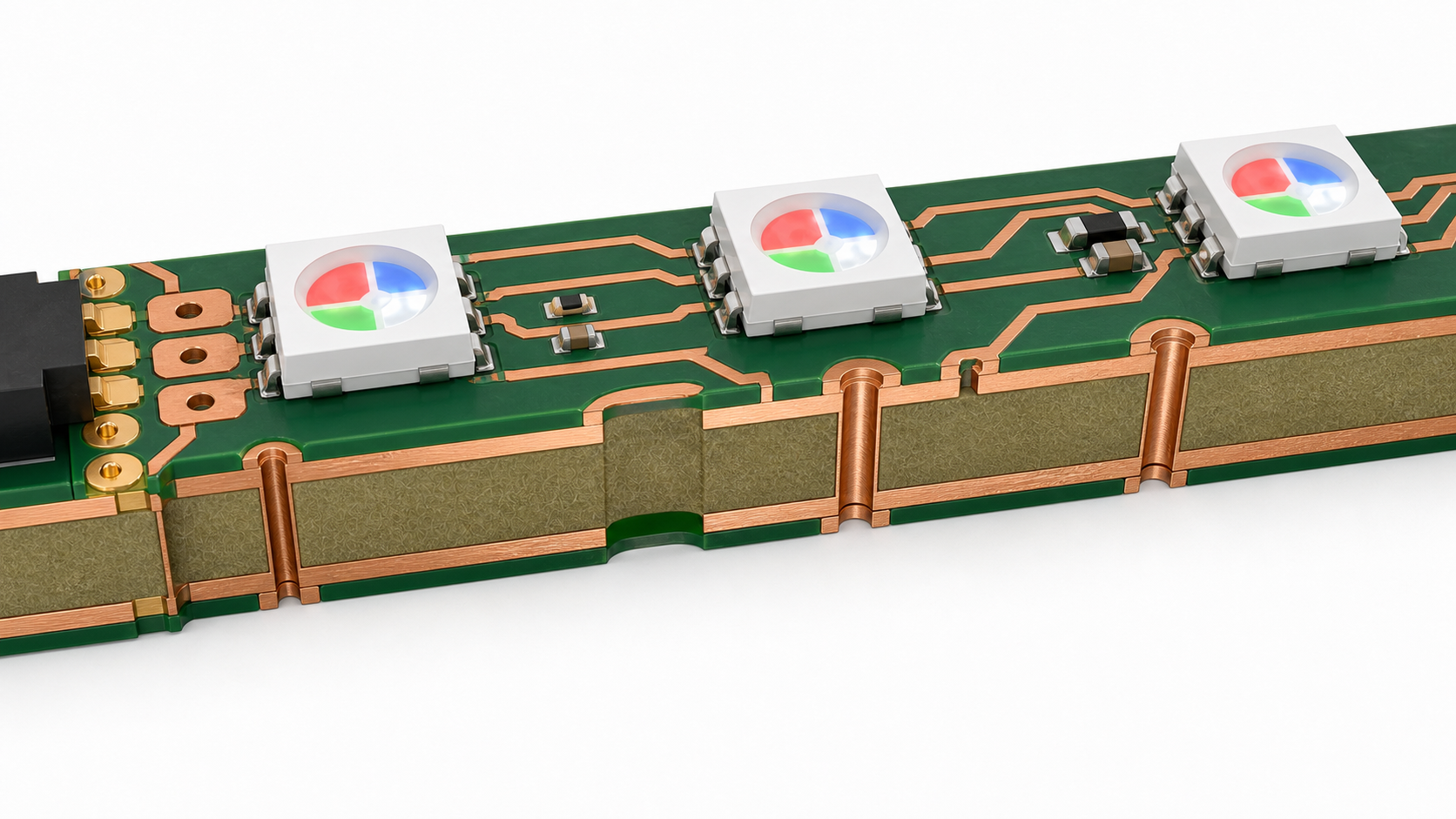
How a 5V Addressable RGB Strip Works
Each addressable RGB LED package includes RGB emitters and a small control circuit, so the controller sends serial data through the strip and each pixel passes the remaining data to the next LED.
With common LED families such as WS2812B and SK6812, the board usually has 5V, GND, data input, and data output paths. The PCB designer must route power rails wide enough for current, maintain clean data routing, place input/output pads clearly, and protect the strip from assembly mistakes.
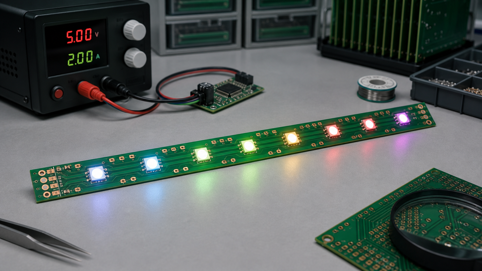
Power Design: 5V, Current, and Voltage Drop
Power distribution is the most common failure point in 5V addressable RGB strips because low voltage means higher current for the same wattage.
When all pixels show bright white, every RGB channel can draw current. The far end of a long strip may receive less than the input voltage because copper traces, wires, connectors, and solder joints all add resistance. The visible symptoms are dim LEDs, yellowish white, random flicker, reset behavior, or color mismatch between the near and far ends.
Power Design Checklist
- Estimate worst-case current: Calculate full-white current from LED datasheets and safety margin.
- Use wide 5V and GND rails: Do not route high-current power as thin signal traces.
- Add power injection pads: Long strips should have feed points at intervals, not only one input end.
- Check connector rating: Connector current rating must match the real strip load.
- Measure voltage at the far end: Test under full-brightness patterns, not only colorful demo effects.
- Consider copper weight: Higher current may require wider copper, thicker copper, or shorter segments.
- Plan heat path: High brightness in an enclosed product needs thermal evaluation.
PCB Design Requirements for Rigid RGB Strips
The PCB layout should be designed around current flow, LED placement accuracy, optical alignment, and assembly test access.
| Design Area | Recommended Engineering Focus | Common Mistake | Supplier Check |
|---|---|---|---|
| LED pitch | Keep pitch consistent for visual uniformity | Changing pitch without updating optics or housing | Ask for SMT placement tolerance and first-article photos. |
| Copper rails | Use wide 5V and GND routing, with enough copper near connectors | Thin rails causing voltage drop and heat | Review Gerber copper width before production. |
| Data line | Route cleanly from DIN to DOUT, with clear direction marking | Confusing input and output pads during assembly | Specify data direction in silkscreen and test fixture. |
| Test pads | Add accessible 5V, GND, DIN, DOUT, and segment test pads | No way to isolate a failing LED chain | Ask whether the factory can test every strip with a fixture. |
| Panelization | Use rails, tabs, V-cut, or routing based on strip shape | Weak tabs breaking LED solder joints during depaneling | Review depaneling method with the PCB supplier. |
| Mounting holes | Keep copper and LEDs away from screw stress zones | Cracking solder joints near mounting points | Confirm mechanical drawing with tolerances. |
LED Selection: WS2812B, SK6812, RGB, or RGBW
The LED IC should be selected by controller compatibility, color requirement, package size, supply voltage, brightness, white channel needs, and availability.
WS2812B-style LEDs are widely used for 5V RGB addressable lighting, while SK6812 variants are common when RGBW or alternate packages are needed. The final choice should be verified against the controller firmware, color order, timing requirements, and supply chain stability. For production, do not substitute LED models without approval because the same footprint can still behave differently in color order, timing, reset behavior, brightness, or thermal performance.
Manufacturing and Assembly Concerns
Rigid addressable RGB strips look simple, but production quality depends on LED handling, solder paste control, reflow profile, depaneling, and full-function testing.
- Moisture sensitivity: LED packages should be stored and baked according to supplier requirements when needed.
- Polarity and orientation: RGB LEDs and data direction must be controlled by BOM, silkscreen, and AOI settings.
- Solder paste volume: Too much paste can create bridging; too little can reduce mechanical strength.
- Reflow profile: Overheating may damage LEDs or create color inconsistency.
- Depaneling stress: Long narrow boards need careful support to avoid bending and solder joint cracks.
- Functional testing: Every strip should be tested for red, green, blue, white, data-through, and current behavior.
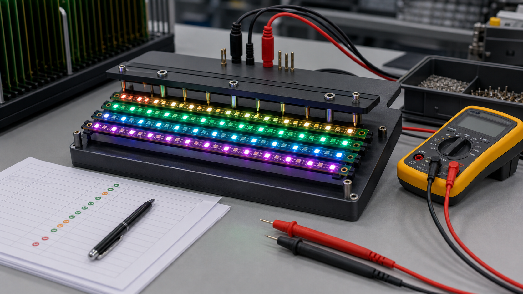
Testing Plan for Production Orders
A reliable supplier should test addressable RGB strips with both electrical and visual methods, not only a quick power-on check.
| Test Item | Purpose | What to Look For | Why Buyers Should Care |
|---|---|---|---|
| Continuity test | Check 5V, GND, and signal paths | Open circuits, shorts, reversed connections | Prevents dead strips before LED test. |
| RGB channel test | Light red, green, and blue separately | Wrong color order, missing channel, damaged LED | Finds assembly and LED defects early. |
| Full-white current test | Measure worst-case current draw | Overcurrent, weak power rails, voltage drop | Important for power supply and connector selection. |
| Data-through test | Confirm the signal passes from pixel to pixel | Broken chain after one LED, bad solder joint, wrong orientation | One bad pixel can disable the downstream section. |
| Visual uniformity check | Review brightness and color consistency | Dim pixels, color shift, uneven soldering or LED bins | Critical for visible lighting products. |
Procurement Checklist Before Ordering
Buyers should send both electrical and mechanical requirements, because a rigid PCB LED strip is part PCB, part lighting product, and part assembly module.
- Target LED IC or accepted alternatives, such as WS2812B, SK6812, RGB, or RGBW.
- Operating voltage, maximum current, expected brightness level, and duty cycle.
- Board length, width, thickness, mounting holes, slots, and outline tolerance.
- LED pitch, LED count, color order, and data direction.
- Copper weight, surface finish, solder mask color, and silkscreen requirements.
- Connector type, cable length, wire gauge, and current rating.
- Testing method, acceptance criteria, packaging, and labeling requirements.
- Whether the strip must pass product-level requirements such as EMC, flammability, or safety review.
Common Failure Modes
Most failures come from power distribution, poor LED soldering, data chain interruption, heat, or mechanical stress.
| Symptom | Likely Cause | Engineering Fix | Production Check |
|---|---|---|---|
| End pixels look dim or yellow | Voltage drop along 5V/GND rails | Wider copper, shorter segments, or power injection | Measure far-end voltage at full white. |
| Pixels flicker randomly | Weak data signal, poor grounding, or unstable power | Improve ground reference, routing, controller level, and power filtering | Run dynamic color sequence tests. |
| All pixels after one LED fail | Broken data output or wrong LED orientation | Check LED direction, solder joints, and DOUT path | Use fixture test to locate chain break. |
| Connector gets hot | Current exceeds connector or wire rating | Use higher-rated connector or multiple feeds | Thermal check during full-brightness burn-in. |
| Board cracks near mounting hole | Mechanical stress or poor hole clearance | Add clearance, support, or change mounting structure | Review mechanical drawing and screw torque. |
FAQ
What is a rigid PCB 5V addressable RGB strip?
It is a non-flexible LED PCB module with individually controllable RGB pixels, usually powered by 5V DC and controlled through a digital data line. It is commonly used in OEM lighting modules, displays, indicators, and custom electronics.
Why choose rigid PCB instead of flexible LED strip?
Rigid PCB is better when the strip must mount flat, hold connectors firmly, maintain LED position, or pass repeatable assembly testing. Flexible strip is better when the installation needs bending around curves.
Is 5V enough for addressable RGB LEDs?
Yes, many addressable RGB LEDs are designed for 5V operation. The key is current planning. Long strips and high-density layouts need wide copper, suitable connectors, and often power injection.
How do I avoid voltage drop on a 5V RGB strip?
Use wide 5V and GND copper, keep high-current paths short, add power injection pads, choose connectors with enough current rating, and test the far-end voltage under full-white brightness.
Can every LED be individually controlled?
With common addressable RGB LEDs, each pixel can usually be controlled individually. However, some higher-voltage or cost-reduced products may group LEDs, so buyers should confirm pixel control before ordering.
What LED ICs are commonly used?
WS2812B and SK6812 families are common examples for 5V addressable RGB or RGBW products. The final choice should match the controller, color order, firmware timing, package, brightness, and availability.
Do rigid RGB strips need test pads?
Yes. Test pads for 5V, GND, DIN, DOUT, and segment points make production testing and fault diagnosis much easier, especially when one LED can interrupt the downstream data chain.
What copper weight should I use?
It depends on current, trace width, strip length, board temperature, and allowed voltage drop. For high-current strips, ask the PCB supplier to review copper width and current path before production.
Can a rigid PCB RGB strip be waterproof?
The PCB itself is not automatically waterproof. Waterproofing may require conformal coating, silicone encapsulation, housing design, or sealed connectors. Each method affects heat, repairability, and optical appearance.
What files should I send to a supplier?
Send Gerber files, BOM, pick-and-place file, mechanical drawing, LED specification, connector requirements, testing requirements, target quantity, packaging needs, and any controller compatibility details.
Can the same design use RGBW LEDs?
Possibly, but RGBW LEDs may have different pinout, current, package, firmware settings, color order, and optical requirements. Do not substitute RGBW without redesign review.
What should be tested before mass production?
Test RGB channels, full-white current, data-through continuity, far-end voltage, visual uniformity, connector heating, mounting fit, and controller compatibility before releasing mass production.
Final Recommendation
A rigid PCB 5V addressable RGB strip is a strong choice when you need a stable, custom, individually controlled lighting module for an OEM product. The design should be reviewed as a complete electrical, mechanical, optical, and manufacturing system, not just as a row of LEDs.
If you’re sourcing reliable PCB/PCBA manufacturing, including OEM, ODM, prototyping, mass production, or custom engineering solutions, reach out to our engineering team for technical support and a quote at sales@bestpcbs.com.
You may also like


Tags: 5V addressable LED strip, custom led pcb, rigid PCB RGB strip, WS2812B PCB