

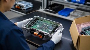
Automotive electronics PCB projects require stable materials, accurate fabrication, reliable soldering, complete inspection and repeatable batch quality. These boards are used in vehicle systems where heat, vibration, humidity, current load and long service life can affect final product reliability.
EBest Circuit provides automotive electronics PCB manufacturing and assembly services from a China source factory. We support prototype PCB, automotive PCB assembly, component sourcing, testing and batch production for global vehicle electronics projects.
Are you facing these production and assembly risks in automotive electronics PCB projects?
- Do material shortages, unstable PCB materials, plating defects or impedance deviation delay your automotive electronics PCB production schedule?
- Are BGA, QFN, connector, fine-pitch component or through-hole soldering defects increasing your automotive PCBA rework cost and approval risk?
- Are BOM changes, component sourcing delays, testing requirements or hidden process costs making your final project budget harder to control?
As a PCB manufacturer with 20+ years of experience, EBest Circuit provides automotive electronics PCB manufacturing and assembly support for vehicle electronics brands, OEM projects, EMS companies and technical teams. Below are our solutions to above problems:
- Manufacturing control: We review Gerber files, stack-up, copper thickness, material selection, impedance requirements and panel design before production to reduce fabrication defects and batch instability.
- Assembly reliability: We support BOM review, component sourcing, stencil design, SMT assembly, through-hole assembly, AOI inspection and X-ray inspection to reduce soldering defects and PCBA rework.
- Cost and delivery control: We confirm fabrication, assembly, testing, coating, programming, packaging and shipment requirements before production to reduce hidden costs, repeated revisions and delivery risks.
Welcome to contact EBest Circuit if you need automotive electronics PCB manufacturing and assembly support: sales@bestpcbs.com.
What Is an Automotive Electronics PCB?
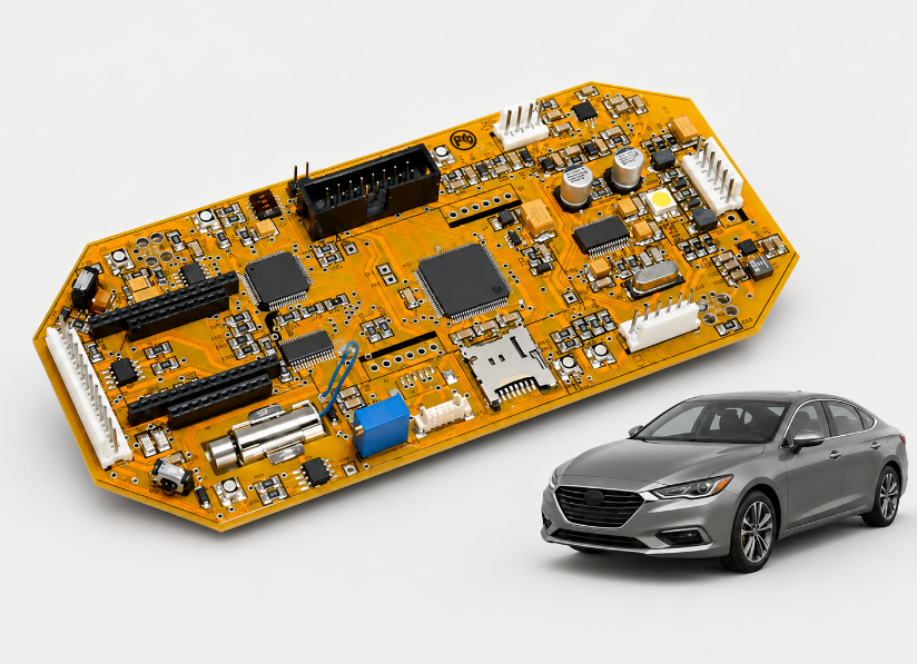
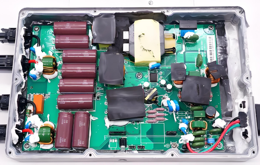
An automotive electronics PCB is a printed circuit board used in vehicle electronic systems to connect, support and control electronic components. It must operate reliably under vibration, heat, humidity, electrical load and long service cycles.
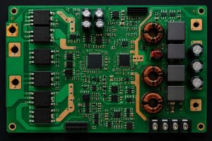
These PCBs are commonly used in body control modules, lighting systems, BMS boards, sensors, infotainment systems, power control units and ADAS-related modules. Compared with simple consumer electronics boards, automotive boards need stronger material control, better process stability and more complete testing.
For vehicle electronics projects, the main concern is not only whether the board can be produced. The more important question is whether the supplier can keep the same reliability from prototype to repeat batch production.
Why Is Automotive Electronics PCB Manufacturing Different from Standard PCB Manufacturing?
Automotive electronics PCB manufacturing is different because vehicle electronics face harsher working conditions and stricter reliability expectations. Standard PCB production may focus mainly on electrical connection, while automotive PCB manufacturing must also control thermal stress, vibration, long-term aging and traceability.
Main differences include:
- Wider temperature conditions: Materials must resist thermal cycling, soldering heat and long-term operating stress.
- Higher vibration risk: Connectors, solder joints and plated holes must remain mechanically stable.
- Longer service life: Vehicle electronics often need many years of stable operation.
- Stricter inspection: AOI, X-ray, electrical testing and functional testing are often combined.
- Better traceability: Material lots, process records and inspection data should be controlled.
For this reason, automotive PCB projects should be reviewed before tooling, not after production problems appear.
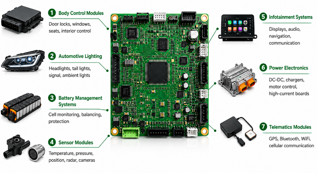
What Are the Main Applications of Automotive Electronics PCB?
Automotive electronics PCB applications cover control, lighting, sensing, power, communication and safety-related vehicle systems. Each application has different requirements for copper thickness, material, thermal design, impedance and assembly quality.
In most vehicle electronics projects, common applications include:
- Body control modules: Door locks, window control, seat control and interior electronics.
- Automotive lighting: LED headlights, tail lights, signal lights and ambient lighting.
- Battery management systems: Cell monitoring, balancing circuits and protection boards.
- Sensor modules: Temperature, pressure, position, radar and camera-related electronics.
- Infotainment systems: Display boards, audio modules, navigation and communication interfaces.
- Power electronics: DC-DC converters, charging modules, motor control and high-current boards.
- Telematics modules: GPS, Bluetooth, WiFi, cellular and vehicle communication systems.
Which PCB Materials Are Commonly Used in Automotive Electronics?
Common automotive PCB materials include FR4, High-Tg FR4, aluminum substrate, polyimide, rigid-flex materials and low-loss laminates. Heavy copper is also common in power boards, but it is a copper thickness option, not a base material.
| Material | Typical Use | Common Range | Main Benefit |
|---|---|---|---|
| FR4 | Body control, sensors, infotainment, general control boards | Tg 130–170°C | Cost-effective and widely available |
| High-Tg FR4 | Engine bay electronics, multilayer boards, power modules | Tg 170°C+ | Better heat resistance |
| Aluminum substrate | LED headlights, tail lights, thermal modules | 1.0–2.0 W/m·K typical thermal conductivity | Strong heat dissipation |
| Polyimide | Flexible PCB, rigid-flex PCB, compact modules | Tg 200°C+ | Better bending and thermal resistance |
| Rigid-flex materials | Camera modules, sensors, compact control systems | Project-specific stack-up | Saves space and reduces connector risk |
| Low-loss laminate | Radar, RF, ADAS and high-speed communication boards | Low Dk / low Df grade | Improves signal stability |
| Heavy copper structure | BMS, DC-DC converters, motor control and high-current boards | 2–6 oz copper or higher | Improves current capacity |
What Are the Design Requirements for Automotive Electronics PCB?
Automotive electronics PCB design should focus on electrical stability, heat control, EMI reduction, vibration resistance and manufacturability. A reliable design can reduce prototype revisions, assembly defects and long-term field failure risks.
- Current capacity: Power traces should use enough line width, copper thickness and copper area. For BMS, motor control, lighting and charging modules, high-current paths should be reviewed together with via quantity and heat dissipation.
- Thermal management: Heat-generating components should be placed near copper planes, thermal vias, heat sinks or aluminum substrate areas. Poor thermal paths may cause LED brightness decay, component aging, solder fatigue or board deformation.
- Signal integrity: High-speed, RF, camera, radar and communication lines should control impedance, return paths, trace length and layer transitions. For compact ADAS and sensor modules, fine-line HDI layouts should be reviewed carefully.
- EMI and grounding: Ground planes should be stable and return paths should be short. Noisy power circuits, RF circuits and sensitive signal areas should be separated to reduce interference, unstable communication and testing failure.
- Mechanical strength: Connectors, mounting holes, large components and heavy parts should avoid weak board edges or narrow breakaway areas. Automotive PCBA may face vibration, insertion force and long-term mechanical stress.
- Assembly reliability: Pad size, solder mask clearance, stencil opening, component spacing and test point access should be checked before production. Good DFA review helps reduce solder bridges, tombstoning, poor wetting and rework.
- Material and stack-up matching: Material, layer count, copper thickness and surface finish should match the application environment. High-Tg FR4, aluminum substrate, polyimide, rigid-flex materials or low-loss laminates may be selected according to heat, bending or signal requirements.
- Testing access: Test points should be reserved for flying probe testing, ICT, functional testing or programming. Without enough test access, fault diagnosis becomes slower and batch production approval may be delayed.
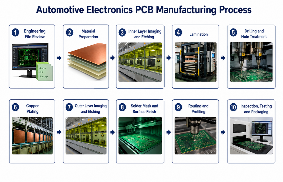
How Does the Automotive Electronics PCB Manufacturing Process Work?
The automotive electronics PCB manufacturing process starts with engineering review and ends with inspection, electrical testing and controlled packaging. Each step must be controlled because small defects in drilling, plating, solder mask or surface finish may affect long-term vehicle reliability.
Step 1: Engineering file review.
The production team checks Gerber files, drill files, stack-up, copper thickness, impedance requirements, material selection, surface finish and tolerance requirements. DFM feedback is provided before production to reduce design and fabrication risks.
Step 2: Material preparation.
Laminate, copper foil, prepreg, solder mask and surface finish requirements are prepared according to the confirmed specification. Material type, thickness, Tg, copper weight and batch information should match the project requirements.
Step 3: Inner layer imaging and etching.
For multilayer automotive PCB, inner layers are imaged, etched and inspected first. AOI is used to check line width, spacing, shorts, opens and circuit accuracy before lamination.
Step 4: Lamination.
Inner layers, prepreg and copper foil are pressed together under controlled temperature, pressure and time. Stable lamination helps reduce delamination, warpage and layer misalignment.
Step 5: Drilling and hole treatment.
Mechanical drilling or laser drilling creates through holes, vias or microvias. Desmear and hole cleaning are then performed to prepare reliable copper plating inside the holes.
Step 6: Copper plating.
Copper is plated onto hole walls and board surfaces to build electrical connections between layers. Plating thickness and hole wall quality are important for vibration resistance and long-term reliability.
Step 7: Outer layer imaging and etching.
The outer circuit pattern is transferred, plated and etched. This step controls final trace width, spacing, pads and copper features.
Step 8: Solder mask and surface finish.
Solder mask is applied to protect copper and define soldering areas. ENIG, OSP, immersion silver or lead-free HASL can be selected according to solderability, storage time and assembly requirements.
Step 9: Routing and profiling.
The PCB is routed, scored or shaped according to the board outline and panel design. Mounting holes, slots and edge quality are checked to support final assembly.
Step 10: Inspection, testing and packaging.
AOI, electrical testing, impedance testing when required, visual inspection and final quality checks are completed before shipment. Boards are packaged with labels and traceability records according to project requirements.
How Does Automotive Electronics PCB Assembly Work?
Automotive electronics PCB assembly turns a bare PCB into a tested PCBA through component sourcing, solder paste printing, SMT placement, reflow soldering, inspection and final testing. Each step must be controlled because solder defects, wrong components or weak testing may affect vehicle electronics reliability.
Step 1: BOM review and component sourcing.
The BOM is checked for part numbers, package sizes, temperature grade, lifecycle status, lead time and approved alternatives. This helps reduce sourcing delays, wrong substitutions and assembly risks before production starts.
Step 2: Stencil and solder paste preparation.
The stencil opening is designed according to pad size, component type and solder volume requirements. Proper solder paste control helps reduce solder bridges, insufficient solder, tombstoning and poor wetting.
Step 3: SMT placement.
SMT machines place resistors, capacitors, ICs, sensors, connectors, BGA, QFN and other components onto the PCB. Placement accuracy is important for fine-pitch components and compact automotive electronics PCB assembly.
Step 4: Reflow soldering.
The assembled board passes through a controlled reflow profile. Temperature control helps protect components, improve solder joint strength and reduce defects caused by overheating or insufficient heating.
Step 5: AOI and X-ray inspection.
AOI checks visible defects such as missing parts, polarity errors, misalignment and solder bridges. X-ray inspection is used for BGA, QFN and bottom-terminated components where solder joints cannot be seen from the surface.
Step 6: Through-hole and mixed assembly.
Connectors, terminals, relays, transformers or high-power parts may require wave soldering, selective soldering or manual soldering. These parts need stronger process control because they often face vibration and insertion force.
Step 7: ICT, functional testing and programming.
ICT checks circuit connection and component placement, while functional testing confirms real operating performance. Programming, calibration, conformal coating or box-build assembly can be added according to project requirements.
What Automotive PCB Manufacturing and Assembly Services Does EBest Circuit Provide?
EBest Circuit provides one-stop automotive PCB manufacturing and assembly services from prototype to batch production. We support PCB fabrication, component sourcing, SMT assembly, through-hole assembly, BGA assembly, testing and box assembly for vehicle electronics projects.
Our services include:
- PCB fabrication: FR4 PCB, multilayer PCB, metal-based PCB, ceramic PCB, flexible PCB, rigid-flex PCB and high-frequency PCB.
- Prototype and quick-turn PCB: Prototype PCB, low-volume production and urgent PCB orders with fast response.
- Automotive PCB assembly: SMT assembly, THT assembly, mixed assembly, BGA assembly, flex PCB assembly and turnkey PCB assembly.
- Component sourcing: Support for SMD, BGA, QFN, QFP and other electronic components through a stable supply chain.
- Testing and inspection: AOI, X-ray inspection, flying probe testing, ICT, functional testing and final inspection before delivery.
- Box assembly: Final assembly, labeling, packaging and 100% inspection before shipment when required.
EBest Circuit can handle 01005 SMD components, 0.25mm minimum BGA pitch, SMT/THT mixed assembly and 1–5 days lead time for selected PCBA projects.
Quality Control for Automotive PCB and PCBA Orders: From Materials to Final Testing
Automotive PCB and PCBA quality control should cover materials, fabrication, assembly, testing, traceability and shipment inspection. Final testing alone is not enough because many reliability risks start from material selection, drilling, plating, soldering or component handling.
- Material inspection: Laminate, copper foil, solder mask, prepreg and surface finish materials are checked against the confirmed specification. Material type, thickness, Tg, copper weight and batch records should match the project requirements.
- Inner layer inspection: For multilayer automotive PCB, inner circuits are inspected before lamination. AOI checks line width, spacing, shorts, opens and pattern accuracy to reduce hidden layer defects.
- Drilling and plating control: Hole size, registration, desmear quality and copper plating thickness are controlled carefully. Reliable hole wall copper is important for vibration resistance, thermal cycling and long-term electrical connection.
- Solder mask and surface finish inspection: Solder mask coverage, opening accuracy, adhesion and surface finish quality are checked before assembly. Poor solder mask or surface finish may cause soldering defects, oxidation or poor wetting.
- SMT process inspection: SPI can check solder paste volume before placement. AOI checks component polarity, missing parts, alignment, solder bridges and visible solder defects after reflow.
- Hidden solder joint inspection: X-ray inspection is used for BGA, QFN, BTC and other hidden solder joints. This helps identify voids, insufficient solder, bridging and weak solder connections.
- Electrical and functional testing: Flying probe testing, ICT and functional testing can be selected according to project needs. These tests help confirm circuit continuity, component operation and final PCBA performance.
- Traceability and final shipment control: Material records, production batches, inspection data, labels and packaging details are controlled before shipment. This supports repeat orders, quality tracking and long-term automotive electronics PCB production.
Automotive Electronics PCB Assembly Case Study: From Prototype to Reliable Batch Production
A reliable automotive electronics PCBA project should move from prototype validation to stable batch production through design review, process control, testing planning and production record management. The following case shows how early review can reduce assembly risk and improve repeatability.
Project background:
A vehicle control module required stable signal transmission, reliable connector strength and long-term solder joint performance. The first prototype design had tight component spacing, limited test points and insufficient copper area around several power components.
Project requirements:
The PCBA needed stable automotive electronics PCB manufacturing, accurate SMT assembly, reliable connector soldering and complete testing before batch approval. The project also required BOM review, X-ray inspection for hidden solder joints, functional testing and controlled packaging for repeat orders.
Our solution:
EBest Circuit reviewed the PCB layout, stack-up, solder mask clearance, copper balance, connector footprint and test point access before production. During assembly, we supported BOM review, component sourcing, stencil design, SMT placement, reflow control, AOI inspection and X-ray inspection to reduce soldering and assembly risks.
Final result:
After prototype validation, the production process, testing method, inspection records and packaging requirements were confirmed for batch manufacturing. The project achieved more stable PCBA assembly, fewer repeated revisions and better consistency for later automotive electronics PCB production.
Why Choose EBest Circuit for Automotive Electronics PCB Manufacturing and Assembly?
EBest Circuit helps automotive electronics projects reduce supplier coordination, production risk, assembly defects and delivery uncertainty. From PCB fabrication to component sourcing, PCBA assembly, testing and box assembly, one-stop support makes prototype and batch production easier to control.
Choose EBest Circuit because:
- Reduce supplier management time: PCB fabrication, component sourcing, SMT assembly, THT assembly, BGA assembly, testing and box assembly can be handled together, reducing communication between multiple suppliers.
- Lower manufacturing risk: Gerber files, stack-up, copper thickness, material selection, impedance requirements and panel design are reviewed before production to reduce fabrication defects and batch instability.
- Improve assembly reliability: Support for 01005 SMD components, 0.25mm minimum BGA pitch, SMT/THT mixed assembly and BGA assembly helps manage compact automotive PCBA projects with fine-pitch components.
- Control component sourcing delays: A stable component supply chain supports SMD, BGA, QFN, QFP and other electronic components, helping reduce BOM delays and unplanned substitutions.
- Shorten project lead time: Selected urgent PCB orders can be shipped within 24 hours, and selected PCBA projects can support 1–5 days lead time depending on complexity and material readiness.
- Support repeat batch production: Process control, inspection records, final testing and packaging control help keep prototype approval, pilot run and batch production more consistent.
If your project needs automotive electronics PCB manufacturing and assembly with controlled cost, reliable inspection and practical production support, EBest Circuit can review your files and provide a quotation.
FAQs About Automotive Electronics PCB
Q1: What is the biggest risk in automotive electronics PCB production?
A1: The biggest risk is hidden reliability failure after delivery. Automotive PCB may pass a basic electrical test but still fail later because of weak solder joints, poor via plating, thermal stress, vibration, contamination or unsuitable material selection.
Q2: What certifications are important for automotive PCB manufacturing?
A2: IATF 16949 and ISO 9001 are important for automotive PCB quality control. Depending on the project, ISO 13485, AS9100D, UL, RoHS and REACH may also support compliance, traceability and market access requirements.
Q3: Does EBest Circuit support automotive PCB assembly?
A3: Yes. EBest Circuit supports SMT assembly, THT assembly, mixed assembly, BGA assembly, prototype PCB assembly, quick-turn PCB assembly and full turnkey PCB assembly. Component sourcing, testing and box assembly can also be added when required.
Q4: What PCB types can be used in automotive electronics?
A4: Common options include FR4 PCB, multilayer PCB, metal-based PCB, ceramic PCB, flexible PCB, rigid-flex PCB and high-frequency PCB. The right choice depends on heat, vibration, space, current load, signal speed and cost requirements.
Q5: Can automotive PCB projects use BGA components?
A5: Yes. BGA components are common in compact control modules, communication boards and high-performance automotive PCBA. EBest Circuit supports BGA assembly and X-ray inspection to check hidden solder joints that cannot be inspected visually.
Q6: What is the minimum BGA pitch EBest Circuit can support?
A6: EBest Circuit supports 0.25mm minimum BGA pitch. For fine-pitch BGA projects, stencil design, reflow profile, PCB flatness, pad design and X-ray inspection should be reviewed before batch production.
Q7: What is the minimum SMD component size supported?
A7: EBest Circuit supports 01005 minimum SMD components. For small components, solder paste control, placement accuracy, reflow profile and AOI inspection are important to reduce tombstoning, shifting and insufficient solder.
Q8: How fast can automotive PCB or PCBA orders be delivered?
A8: Selected urgent PCB orders can be shipped within 24 hours, and PCBA lead time can be 1–5 days depending on project complexity. Material availability, BOM status, testing requirements and order quantity will affect the final delivery schedule.
Q9: Can EBest Circuit provide full turnkey automotive PCBA?
A9: Yes. Full turnkey PCBA can include PCB fabrication, component sourcing, SMT assembly, THT assembly, BGA assembly, inspection, testing, packaging and shipment. This helps reduce supplier coordination and project management time.
Q10: Why choose a China source factory for automotive PCB projects?
A10: A China source factory can support custom PCB fabrication, component sourcing, flexible production volume and cost control in one supply chain. EBest Circuit also supports global delivery without false local factory or overseas warehouse claims.
Q11: How can soldering defects in automotive PCBA be reduced?
A11: Soldering defects can be reduced through stencil review, solder paste control, accurate SMT placement, reflow profile control, AOI inspection and X-ray inspection. BGA, QFN, connectors and fine-pitch parts should receive extra process attention.
Q12: Does automotive PCB assembly require functional testing?
A12: Functional testing is strongly recommended when the PCBA must meet real operating requirements. ICT can check circuit connection, while functional testing confirms whether the assembled board performs correctly under the required working conditions.
Q13: How do I choose an automotive electronics PCB manufacturer?
A13: Choose a manufacturer with PCB fabrication, PCBA assembly, component sourcing, testing capability, quality certifications and traceability control. For automotive electronics, stable production and inspection capability matter more than only low unit price.
Automotive electronics PCB projects need stable materials, controlled fabrication, reliable assembly, complete testing and repeatable batch quality. The right supplier should support PCB manufacturing, component sourcing, SMT assembly, BGA inspection, functional testing and final delivery together, so production risks can be found earlier and controlled before shipment.
EBest Circuit provides automotive electronics PCB manufacturing and assembly services from a China source factory, supporting prototype, low-volume and batch PCBA projects for global vehicle electronics applications. If you need automotive PCB fabrication, component sourcing, PCBA assembly, testing or box assembly, send your Gerber files, BOM, quantity and testing requirements for quotation: sales@bestpcbs.com.
You may also like


Tags: Automotive Electronics PCB, Automotive Electronics PCB Assembly, Automotive Electronics PCB Design, Automotive Electronics PCB Manufacturing