How can high frequency PCB for automotive radar help reduce signal loss and improve 77GHz ADAS module stability? In automotive radar design, small changes in material, stackup, antenna geometry, or impedance can affect detection range and signal consistency. This guide explains the practical PCB factors that influence radar performance, from material selection and DFM review to surface finish, reliability control, and mass production support.
How Does a High Frequency PCB for Automotive Radar Work in a 77GHz Radar Module?
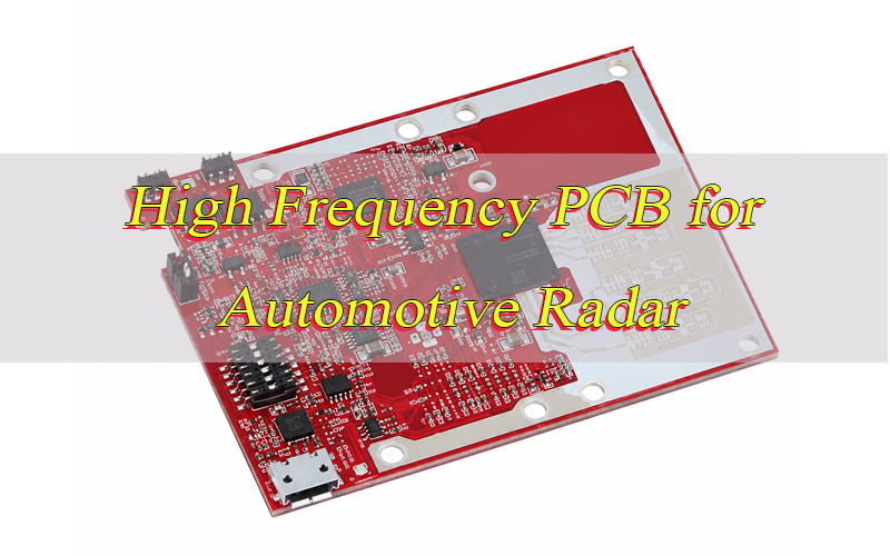
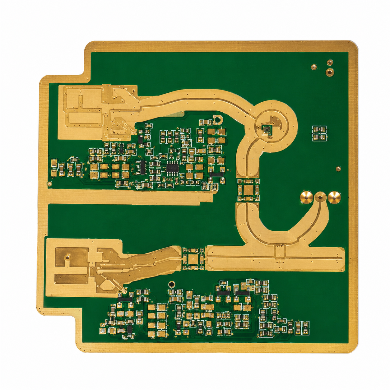
A high frequency PCB inside a 77GHz radar module is not only used to connect components. It also supports RF signal transmission, antenna behavior, grounding, power distribution, and mechanical integration inside the radar housing. Because the radar signal works at millimeter-wave frequency, the PCB structure becomes part of the signal path.
- It transfers RF signals from the radar IC to the antenna area
The radar transceiver generates high-frequency signals. These signals move through microstrip lines, stripline structures, feedlines, vias, and antenna networks on the PCB. At 77GHz, even a small change in line width, dielectric thickness, or copper surface condition may affect insertion loss and impedance. - It may form the antenna directly on the board
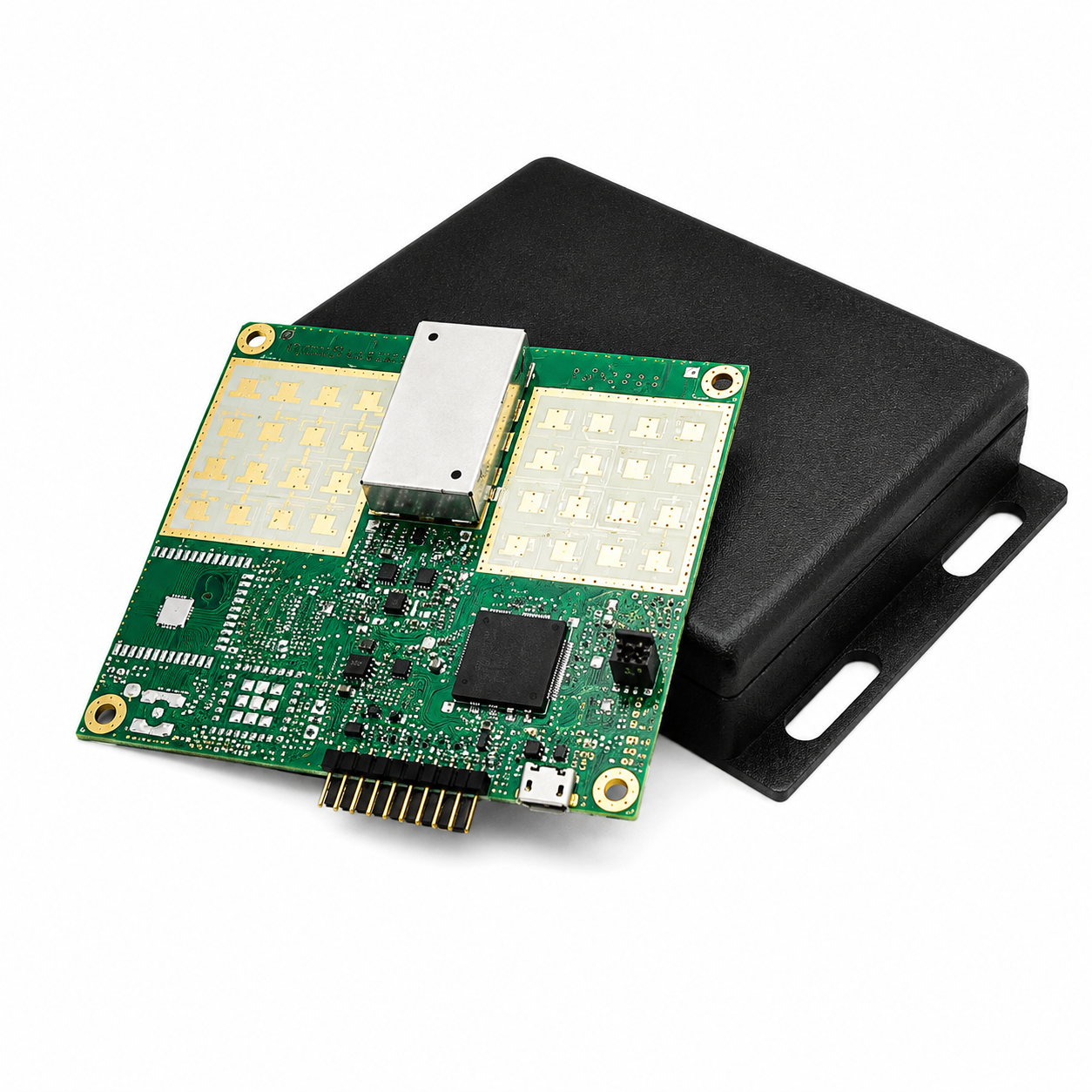
Many automotive radar modules use PCB antenna arrays. In this design, antenna patches or antenna feed networks are created by copper patterns. The PCB manufacturer is not just fabricating copper traces. It is producing a functional RF structure. - It helps receive reflected signals
Radar signals are transmitted outward and reflected by vehicles, pedestrians, road barriers, or nearby objects. The receiving antenna collects the reflected signal and routes it back to the radar IC. The radar system then calculates distance, speed, angle, and movement. - It provides a stable ground reference
Ground layers are critical in radar PCB design. A continuous ground plane helps reduce unwanted radiation, signal reflection, and noise coupling. If the ground path is broken or poorly connected, the RF path may become unstable. - It supports power, digital, and interface circuits
A radar PCB may also include power management circuits, MCU or DSP control sections, CAN interface, Ethernet interface, shielding contacts, and connectors. These areas should be arranged carefully to avoid interference with sensitive RF sections. - It must fit the radar enclosure
The PCB must match the radar housing, radome, connector position, screw holes, thermal path, and shielding cover. Poor mechanical matching may create stress, warpage, or assembly difficulty.
In short, the board is part of the radar system. Good PCB design helps the radar module perform more consistently during testing, assembly, and long-term vehicle operation.
Where Is High Frequency PCB Used in Automotive Radar Applications?
High frequency PCB is used in different radar positions around the vehicle. Each position has different requirements for detection range, field of view, module size, antenna arrangement, and environmental reliability. That is why one radar PCB design may not be suitable for all automotive radar applications.
- Front long-range radar
Front radar is commonly used for adaptive cruise control, forward collision warning, and automatic emergency braking. These modules need stable long-distance signal transmission. The PCB should offer low RF loss, accurate antenna geometry, and good phase consistency. - Corner radar
Corner radar is used for blind spot detection, lane change assistance, and cross-traffic alert. These modules are usually compact, so the PCB needs efficient antenna layout and controlled RF routing in a limited space. - Rear radar
Rear radar supports reverse warning, rear collision detection, and parking assistance. The PCB must maintain stable performance in environments where moisture, vibration, dust, and temperature changes may occur. - Short-range radar
Short-range radar is often used for parking systems and nearby object detection. The PCB may require dense antenna structures and precise copper pattern control because the module needs accurate short-distance sensing. - In-cabin radar
In-cabin radar can be used for occupant sensing, child presence detection, and gesture recognition. These boards often need compact layout, controlled radiation behavior, and good compatibility with plastic housings. - Advanced imaging radar
Imaging radar requires more channels and higher signal processing capability. The PCB may need tighter phase control, more complex routing, and better production repeatability.
For all these applications, the PCB must do more than meet basic electrical continuity. It must support stable radar sensing under real vehicle conditions.
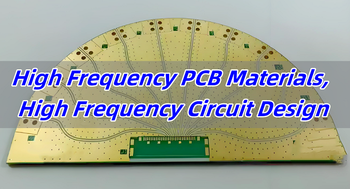
What PCB Material Should Be Used for 77GHz Automotive Radar?
Material selection is one of the most important decisions in a high frequency PCB for automotive radar. The substrate controls dielectric loss, signal speed, antenna resonance, impedance behavior, and long-term stability. A material that works well for ordinary control circuits may not be suitable for 77GHz RF transmission.
- Low-loss high-frequency laminate is usually required for the RF area
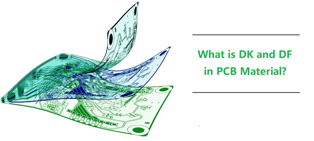
At 77GHz, dielectric loss becomes a major concern. A low-loss material helps reduce signal attenuation from the radar IC to the antenna. This is especially important for front radar and long-range sensing. - Stable Dk helps maintain predictable antenna behavior
Dk means dielectric constant. If Dk changes too much with frequency, temperature, or production batch, the antenna and RF traces may behave differently from the design model. Stable Dk helps keep the radar frequency response more predictable. - Low Df helps reduce energy loss
Df means dissipation factor. Lower Df usually means lower dielectric loss. For millimeter-wave radar, this helps preserve signal strength and improve RF efficiency. - Copper foil type should be reviewed
Copper roughness matters at high frequency. Rougher copper may increase conductor loss. For sensitive RF feedlines and antenna areas, smoother copper can support more consistent signal transmission. - FR4 can be used only in non-critical areas
FR4 may be suitable for digital control, power circuits, or mechanical support layers. However, it is usually not a good choice for 77GHz antenna and RF feedline areas because its dielectric properties are not stable enough for high-performance millimeter-wave transmission. - Hybrid stackup is common in radar modules
Many radar boards combine high-frequency laminate for the RF layer with FR4 for digital or power layers. This can reduce total cost while keeping the RF area stable. - Material availability matters for mass production
A material may perform well in prototype, but if it is difficult to source consistently, it may create problems later. Engineers should confirm material availability before approving the design for production.
A practical material choice should balance RF performance, cost, manufacturability, reliability, and supply stability.
How Should the PCB Stackup Be Designed for Automotive Radar?
Stackup design controls how copper layers, dielectric materials, ground planes, and signal paths work together. For automotive radar, stackup is not just a mechanical layer arrangement. It directly affects RF performance, antenna behavior, impedance control, warpage, and assembly quality.
- Place the RF antenna layer carefully
Many radar modules place the antenna on the top layer. This makes copper geometry, surface finish, and solder mask control very important. If the antenna layer is changed later, the radar performance may need to be revalidated. - Control dielectric thickness tightly
The distance between the antenna copper and ground plane affects antenna resonance and impedance. Loose dielectric thickness tolerance may cause frequency shift or inconsistent signal behavior. - Use a continuous ground reference layer
A stable ground plane helps control RF return current and reduce unwanted coupling. Ground voids, splits, or poorly connected areas may create unpredictable RF results. - Review hybrid lamination carefully
If the board combines high-frequency laminate and FR4, the manufacturer must check bonding strength, thermal expansion difference, lamination pressure, and warpage risk. - Keep the structure balanced
A symmetrical or well-balanced stackup helps reduce board bending. This is important for SMT assembly, radar IC mounting, shielding installation, and final module assembly. - Manage RF vias and transitions
Poor via transitions can create impedance discontinuity. Long via stubs, weak grounding, or uncontrolled launch structures may reduce signal quality. - Separate RF, digital, and power areas
Switching power circuits and digital signals should be kept away from sensitive RF paths. Proper layer planning helps reduce coupling and noise. - Keep the approved stackup unchanged after validation
Once a radar board passes RF validation, changes to material, dielectric thickness, copper type, or layer sequence should be controlled carefully.
A good stackup design reduces the gap between simulation, prototype testing, and real production results.
Why Is Antenna Area Control Critical in Automotive Radar PCB Manufacturing?
The antenna area is one of the most sensitive regions on a high frequency PCB for automotive radar. When the antenna is formed directly by copper patterns, the PCB manufacturer is effectively producing the radar’s transmitting and receiving structure. This area needs much tighter control than ordinary signal routing.
- Antenna dimensions affect frequency response
If the antenna patch is slightly larger or smaller than designed, the antenna response may shift. Over-etching or under-etching can change the effective antenna size. - Feedline accuracy affects matching
The feedline connects the radar IC to the antenna. If the line width or spacing changes, impedance may shift and signal reflection may increase. - Element spacing affects phase consistency
Radar antenna arrays depend on consistent spacing between antenna elements. Uneven spacing may affect angle detection and beam behavior. - Solder mask can change the dielectric environment
If solder mask covers an area that should remain open, it may change local capacitance and dielectric loading. This can affect antenna performance. - Surface finish may influence RF behavior
Different finishes have different metal layers and thicknesses. In sensitive antenna regions, the finish should be selected and controlled carefully. - Layer alignment must be controlled
The antenna layer and reference ground layer need proper alignment. Misregistration may affect the RF field and antenna behavior. - Panelization can influence consistency
The position of the board inside the production panel may affect etching uniformity. For radar antenna arrays, the manufacturer should consider whether the panel layout creates dimensional variation.
Before production, the drawing should clearly define antenna tolerance, solder mask opening, copper thickness, surface finish, inspection points, and RF keep-out areas.
How Does Controlled Impedance Affect Radar Signal Transmission?
Controlled impedance helps RF signals travel through the PCB with predictable behavior. If impedance changes along the signal path, part of the signal may reflect back. In radar modules, this can increase loss, reduce signal quality, and make calibration more difficult.
- Trace width must match the stackup
A 50-ohm RF line depends on trace width, dielectric thickness, copper thickness, and material Dk. The manufacturer should calculate the line width based on real material data. - Etching tolerance affects impedance
If the finished trace is narrower or wider than expected, impedance changes. For 77GHz designs, this variation can be significant. - Reference plane distance must be stable
The distance between RF trace and ground layer controls impedance. If dielectric thickness varies, impedance may drift. - Solder mask condition should be confirmed
Whether the RF trace is covered by solder mask or exposed can affect impedance. This should be defined before production. - Vias and bends need special attention
RF vias, bends, launch structures, and transitions may create discontinuity. Smooth transitions help reduce reflection. - Impedance coupons may be required
Test coupons help verify whether the fabricated board meets impedance requirements. They are useful for production control. - Repeat orders must follow the approved process
Material substitution, copper thickness change, or stackup change may alter impedance. Such changes should not be made without engineering review.
Controlled impedance is not a decoration on the drawing. It is a manufacturing requirement that directly affects radar signal stability.
What Are the Main Manufacturing Challenges of Automotive Radar PCB?
Automotive radar PCB manufacturing is difficult because it combines millimeter-wave RF requirements with automotive-level consistency. The manufacturer must control fine copper features, hybrid materials, surface finish, flatness, and inspection records at the same time.
- Fine RF trace etching
Small RF lines and gaps need precise etching compensation. If the etching process is unstable, impedance and antenna geometry may shift. - Antenna copper accuracy
Antenna patterns must match the design closely. Small copper deviations can affect resonance, gain, and phase response. - Hybrid material lamination
High-frequency materials and FR4 may expand differently during lamination. This can create warpage, bonding stress, or registration issues. - Copper roughness control
At 77GHz, the copper surface becomes important. The manufacturer should understand how copper foil type affects conductor loss. - Via plating quality
Radar boards may include dense grounding vias and signal transitions. Poor via plating can reduce reliability and affect electrical performance. - Solder mask registration
Mask shift near antenna or RF traces may change the local RF environment. Mask opening requirements must be followed accurately. - Board flatness
Warpage can affect SMT assembly and module housing installation. A warped PCB may also create stress on radar ICs or connectors. - Surface finish consistency
The finish must support both soldering and RF requirements. Inconsistent finish thickness may create assembly or performance concerns. - Batch repeatability
Automotive customers need stable quality over time. The same material, process, and inspection method should be used from prototype to mass production.
The real challenge is not producing one good sample. It is producing stable boards again and again.
How Should DFM Review Be Done Before Automotive Radar PCB Production?
DFM review is a key step before producing a high frequency PCB for automotive radar. Many RF problems are hard to fix after the board has been fabricated. A good DFM review can identify risks before they become expensive prototype failures.
- Check the material specification
The manufacturer should confirm laminate brand, grade, thickness, copper type, and material availability. Any unclear material description should be clarified before quotation or production. - Review the stackup carefully
Stackup review should include dielectric thickness, copper thickness, layer sequence, ground reference, and hybrid lamination feasibility. - Confirm impedance requirements
The target impedance, tolerance, trace width, and test method should be confirmed. If the drawing only says “controlled impedance” without details, the manufacturer should ask for clarification. - Inspect the antenna area
The antenna pattern should be reviewed for copper tolerance, solder mask opening, surface finish, and dimensional inspection needs. - Check solder mask rules
RF traces and antenna patches may need larger solder mask clearance or complete mask opening. This should not be left to default factory rules. - Review via structures
The manufacturer should check via placement, grounding vias, via stubs, via-in-pad risk, and plating requirements. - Confirm surface finish
The finish should support both SMT assembly and RF performance. For sensitive RF areas, the finish selection may need extra review. - Evaluate copper balance and warpage risk
Uneven copper distribution may cause board bending. Copper balancing should be reviewed without disturbing RF areas. - Review panelization
Panel design should support stable etching, assembly handling, and antenna consistency. - Define inspection requirements
AOI, impedance testing, electrical testing, microsection, dimensional inspection, and final inspection should be specified clearly.
A strong DFM review helps customers reduce avoidable errors and prepare the design for repeatable production.
What Surface Finish Is Suitable for Automotive Radar PCB?
Surface finish protects exposed copper and supports soldering. In automotive radar PCB, it may also affect RF performance, especially when antenna patterns or RF feedlines are exposed. The best finish depends on the antenna design, assembly process, storage time, and reliability requirements.
- ENIG
ENIG offers good solderability, flatness, and storage stability. It is commonly used in many PCB applications. However, the nickel layer should be reviewed when it appears in RF-sensitive areas. - Immersion silver
Immersion silver provides a flat and conductive surface. It can be suitable for RF applications, but storage and handling conditions should be controlled to avoid tarnish or contamination. - OSP
OSP is flat and simple. It avoids extra metal layers, which may be useful in some RF designs. However, it has shorter shelf life and requires careful assembly planning. - Immersion tin
Immersion tin provides a flat solderable surface. It may be used in some designs, but process control and whisker risk should be considered. - Selective finish
Some radar boards may need different treatment for antenna areas and component soldering pads. This should be clearly marked in the fabrication notes.
When selecting surface finish, we should consider:
- Whether the antenna area needs exposed copper
- Whether nickel is acceptable in RF areas
- Whether the radar IC requires fine-pitch assembly
- How long the boards will be stored before SMT
- Whether the finish meets automotive reliability requirements
- Whether drawing notes clearly separate RF and soldering areas
Surface finish should not be selected only for solderability. For radar boards, RF behavior and assembly reliability must be reviewed together.
How to Ensure Reliability for High Frequency PCB for Automotive Radar in Harsh Environments?
Automotive radar modules work in demanding environments. They may face high temperature, low temperature, vibration, humidity, dust, road salt, and long service life. The PCB must remain stable both electrically and mechanically.
- Material traceability
Material batch records should be kept for laminate, prepreg, copper foil, surface finish chemistry, and other key production materials. - Lamination process control
Temperature, pressure, time, and bonding quality should be controlled during lamination. This is especially important for hybrid stackups. - Copper plating inspection
Hole wall copper thickness and plating quality affect long-term reliability. Poor plating can create failures under thermal cycling or vibration. - Microsection analysis
Microsection inspection helps verify plating, dielectric condition, layer registration, and lamination quality. - AOI inspection
AOI helps detect open circuits, shorts, under-etching, over-etching, and copper pattern issues in RF and antenna areas. - Electrical testing
Electrical testing confirms continuity and isolation. It is a basic but important step before shipment. - Impedance verification
Impedance testing helps confirm that the RF transmission path matches design requirements. - Dimensional inspection
Critical antenna dimensions should be inspected when required. This helps control RF consistency. - Solderability testing
Surface finish quality should support reliable SMT assembly. - Ionic contamination control
Cleanliness matters for long-term reliability. Residue on the board may create leakage or corrosion risk. - Warpage inspection
Board flatness should be checked, especially when radar ICs, shields, or connectors require precise assembly. - Documentation control
Inspection reports, material records, and shipment traceability should be available for customer review.
Reliability is not created by one final test. It comes from stable material, controlled process, careful inspection, and complete documentation.
How Can a Manufacturer Support High Frequency PCB for Automotive Radar Projects?
A qualified PCB manufacturer should support the project before production begins. For 77GHz radar PCB, early communication can help customers reduce design risk, control cost, and improve the chance of successful validation.
- Material selection support
The manufacturer can help compare high-frequency laminates based on Dk, Df, copper type, thickness, availability, and cost. - Stackup review
The manufacturer can check whether the stackup supports impedance, antenna behavior, lamination, and board flatness. - Controlled impedance calculation
Trace width should be calculated using real laminate data and finished copper thickness. This helps reduce mismatch between design and production. - DFM pre-check
The manufacturer can review antenna areas, RF traces, solder mask openings, vias, surface finish, panelization, and assembly risks. - Prototype fabrication
Prototype boards should be made with production-aware methods. This helps make later small-batch production smoother. - Small-batch production support
After prototype validation, the manufacturer should keep the approved material, stackup, and process conditions stable. - Mass production consistency
For automotive projects, consistency matters as much as capability. The manufacturer should maintain clear process records and inspection standards. - Inspection and testing support
AOI, electrical testing, impedance testing, microsection, X-ray when required, and dimensional inspection help improve quality confidence. - Traceability support
Material and production records help customers manage automotive quality requirements and future audits. - Assembly coordination
Radar modules often require fine-pitch components, shields, connectors, and thermal structures. PCB fabrication should be reviewed together with SMT assembly needs.
EBest Circuit supports high-frequency PCB fabrication, controlled impedance production, hybrid stackup review, DFM pre-check, prototype manufacturing, and batch production for automotive electronics, RF modules, radar boards, communication equipment, and advanced sensing applications.
Application Case: Solving a 77GHz Radar PCB Prototype Issue
Customer Background
A customer was developing a compact 77GHz automotive radar module for ADAS testing. The PCB included radar IC pads, RF feedlines, PCB antenna patterns, digital control circuits, and power management sections. The customer needed prototype boards for functional testing before moving to a pilot run.
Project Challenge
During the initial engineering review, several risks were found:
- The RF layer material was not clearly specified.
- Dielectric thickness tolerance was missing.
- Antenna solder mask opening was not defined.
- Some RF feedlines required impedance confirmation.
- Hybrid stackup created possible warpage risk.
- Critical antenna dimensions were not marked for inspection.
- Surface finish notes did not separate RF and soldering requirements.
- Panelization had not been reviewed for antenna consistency.
These issues could affect both prototype testing and future repeat production. Even if the board passed basic electrical testing, the radar module might still show unstable RF performance.
Our Solution
The engineering team reviewed the Gerber files, stackup, material options, antenna layout, RF traces, and fabrication notes. Then several practical improvements were suggested:
- Confirmed a suitable high-frequency laminate for the RF antenna layer.
- Clarified dielectric thickness and finished copper requirements.
- Defined solder mask opening for antenna and RF-sensitive areas.
- Reviewed controlled impedance traces before production.
- Checked copper balance to reduce warpage risk.
- Added inspection points for antenna dimensions.
- Confirmed surface finish requirements for assembly and RF areas.
- Reviewed panelization to improve production consistency.
- Prepared clearer production notes for repeat orders.
Result
The revised prototype was easier to fabricate and more suitable for radar module validation. The customer completed SMT assembly and used the boards for functional testing. After design confirmation, the project moved toward small-batch production with clearer manufacturing requirements.
This case shows a practical point: in 77GHz radar PCB projects, small details can affect both RF performance and production repeatability. Early DFM review helps reduce avoidable delays and supports smoother project transfer.
FAQs About High Frequency PCB for Automotive Radar
Q1: What frequency range is commonly used in modern automotive radar?
A1: Many modern automotive radar modules operate around 77GHz, often within the 76GHz to 81GHz range. This range supports distance detection, speed measurement, and object tracking for ADAS functions.
Q2: Is RO3003 the only material choice for 77GHz radar PCB?
A2: No. RO3003 is a common option, but other low-loss high-frequency laminates may also be suitable. The final choice depends on antenna design, loss target, stackup, cost, and production stability.
Q3: Can FR4 be used anywhere in a radar PCB?
A3: Yes. FR4 can be used in digital, power, or mechanical support areas. However, the 77GHz RF feedline and antenna areas usually need low-loss high-frequency material.
Q4: Why is copper roughness important in millimeter-wave PCB design?
A4: At high frequency, current flows close to the copper surface. Rough copper can increase conductor loss. Smoother copper helps improve RF consistency.
Q5: Should solder mask be removed from radar antenna areas?
A5: It depends on the antenna design. Some antenna areas require solder mask opening to avoid changing the local dielectric environment. This should be clearly defined in the fabrication drawing.
Q6: Why can a radar PCB prototype pass once but fail in later production?
A6: Possible reasons include material substitution, dielectric thickness drift, copper tolerance variation, surface finish change, panelization difference, or unclear production notes.
Q7: What files should customers provide for radar PCB quotation?
A7: Customers should provide Gerber files, stackup, material requirement, copper thickness, impedance data, surface finish, solder mask notes, antenna tolerance, inspection requirements, and expected quantity.
Q8: What is the biggest mistake in 77GHz radar PCB preparation?
A8: A common mistake is treating the antenna area like normal copper artwork. In reality, antenna geometry, solder mask, surface finish, and dielectric thickness all affect radar performance.
Q9: Does surface finish affect automotive radar PCB performance?
A9: It may affect sensitive RF areas, especially when antenna patterns or feedlines are exposed. The finish should be selected based on both soldering needs and RF behavior.
Q10: Why is DFM review important before radar PCB production?
A10: DFM review helps identify risks before fabrication. It can prevent issues related to material choice, stackup, impedance, antenna copper, solder mask, via design, warpage, and surface finish.
Conclusion
A high frequency PCB for automotive radar must support stable 77GHz signal transmission, accurate antenna behavior, controlled impedance, and reliable operation in harsh vehicle environments. It is part of the radar module’s RF performance, not only a carrier for electronic components.
For successful development, customers should review material selection, stackup design, antenna area control, impedance management, solder mask strategy, surface finish, DFM feedback, inspection plan, and traceability records before production starts.
A professional high-frequency PCB manufacturer can help reduce prototype risk and improve production consistency. With early engineering review and controlled manufacturing, automotive radar PCB projects can move more smoothly from design validation to mass production.
You may also like


Tags: high frequency pcb, High Frequency PCB for Automotive Radar, High Frequency PCB for Automotive Radar Design, High Frequency PCB for Automotive Radar Manufacturing