A high-current PCB shunt can show an apparent current even when the load is off. Dissimilar metal junctions at different temperatures can generate a thermoelectric voltage that adds to the tiny shunt signal. Measure at a documented thermal state and separate offset, resistance drift and sense-layout errors before changing calibration.
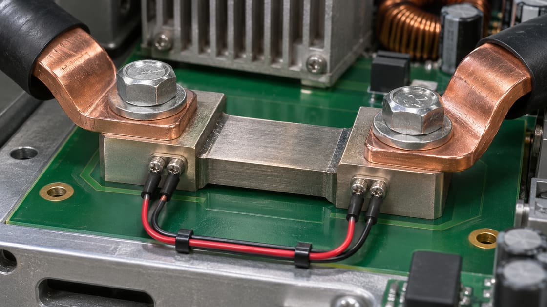
What thermal EMF means in the shunt path
Thermal electromotive force is a voltage caused by temperature differences in a circuit with dissimilar materials. At the differential input, the measured offset depends on how the junction contributions combine. A uniform warm board is not the same condition as unequal terminal temperatures. See Vishay’s technical note on thermal EMF for an example of a controlled terminal temperature imbalance.
Why small offsets matter
A low resistance minimizes voltage drop at high current. It also produces a small voltage per ampere. That makes a few microvolts meaningful, especially at light load or when checking the zero point just after a high-current event.
Parameters to record
Record both the electrical stimulus and thermal state.
| Parameter | Unit | Example or record |
| Nominal shunt resistance | μΩ | 100, illustrative |
| Residual offset | μV | 5, illustrative |
| Sense terminal temperatures | °C | Both sides, and measurement locations |
| Applied current | A | Magnitude, polarity and timing |
| Acquisition | Time and bandwidth | Settling, instrument range and filter state |
Convert microvolts to apparent current
For an illustrative 100 μΩ shunt, 5 μV divided by 100 μΩ equals 0.05 A. That is 50 mA of apparent current if the measurement treats all voltage as resistive drop. The values are an example, not a component accuracy specification.
Thermal EMF vs gain drift vs sense pickup
First determine how the error behaves when current or temperature changes.
| Candidate | Typical diagnostic clue | Useful follow-up |
| Thermal EMF | Offset changes with terminal temperature difference | Observe zero as the board cools |
| Resistance drift | Voltage-per-amp changes with thermal state | Compare slope at controlled temperature |
| Pickup or shared copper drop | Reading changes with switching or power routing | Review Kelvin nodes and measure at the input |
Check the two sense attachment points
Use the shunt supplier’s specified Kelvin points and take the sense conductors away from load current copper. See the four-terminal PCB sensing guide for the separate routing problem. Kelvin wiring reduces unwanted series voltage drop; it does not automatically cancel thermoelectric voltages.
Find unequal heating around the terminals
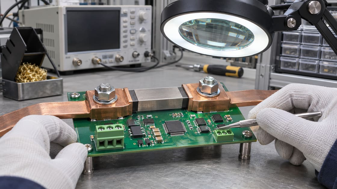
Compare the two ends after the same operating event. A large bus connection, nearby switch, air jet or asymmetric copper area can affect one side more than the other. Record temperatures near the relevant junctions rather than using an unrelated board average.
Compare cold zero and post-load zero
Measure the zero-current output before and after an approved operating event. Confirm the load really is off, allow the input to settle electrically, and log the offset over time. A decaying offset that correlates with a thermal gradient is useful evidence, not proof that every microvolt comes from the shunt.
Use current reversal only on a suitable test setup
For an isolated resistive fixture where safe equal positive and negative currents are authorized, keep voltage lead orientation fixed. If offset is stable, half the difference of the signed readings estimates the resistive voltage, and half their sum estimates the offset. Do not reverse a live product or a unidirectional power stage to try this.
Know when reversal does not cancel the error
The calculation assumes the offset stays effectively constant between measurements. If the sample warms, cools or settles differently during the two readings, residual error remains. Check repeatability in the approved lab setup; do not claim the result cancels all errors.
Choose a corrective action from the evidence
If the offset follows temperature imbalance, examine junction symmetry, nearby heat sources and attachment geometry. If the problem instead follows current, confirm the resistance and placement of sense points. Test one change at a time so you can identify what improved the result.
Record the condition for the next revision
Save the stackup, shunt part, sense coordinates, load history, terminal temperatures and raw signed readings. For PCB manufacturing review, send the layout and test requirements to Best Technology at sales@bestpcbs.com.
FAQ
Does zero-current offset prove a thermoelectric problem?
No. The amplifier, ADC, wiring and external instruments can also contribute offset. Check the actual input with a suitable measurement, compare cold and warm conditions, and isolate candidate sources before assigning the entire error to a temperature difference at the shunt.
Will four-wire sensing eliminate thermal EMF?
No. Four-wire sensing separates the voltage measurement from the power leads, reducing shared resistance errors. Thermoelectric voltages along the actual sense circuit can still appear at the input. Layout and temperature symmetry remain useful even when the Kelvin connection is correct.
Can I subtract a single offset in firmware?
Only if the calibration procedure shows that the offset remains within budget across the intended thermal and operating conditions. A cold zero correction may not compensate a gradient that develops after loading. Check repeatability and temperature dependence before making a fixed correction.
How is thermal EMF different from TCR?
Thermal EMF is an additive voltage. Temperature coefficient of resistance describes how the resistance itself changes with temperature, affecting the slope of voltage versus current. Both can occur together, so compare both offset and gain under controlled conditions when diagnosing error.
Does averaging readings automatically solve this?
Ordinary averaging can reduce some noise, but it cannot remove a stable additive offset. A specific compensated procedure can help only if its assumptions hold. Save the raw readings and record the method so another engineer can verify the improvement.
Is a lower-resistance shunt always more accurate?
No. It reduces power loss for a given current but also reduces signal per ampere. The same voltage offset then represents more current error. Balance thermal limits, resolution and the low-current error budget against the full range required by the product.
Can I infer the offset from a thermal camera alone?
No. A thermal image helps locate uneven heating, but it does not measure the net thermoelectric voltage. Use the image to choose temperature and voltage measurement points, then correlate the electrical data with time and the actual thermal conditions observed.
What should I do on a system that cannot reverse current?
Do not force a reverse condition. If the approved test plan allows it, compare offset during a verified zero-current interval or use an isolated coupon and a suitable lab method. Document which contribution remains unresolved when the operating setup limits the test.
You may also like


Tags: Current Shunt, High Current PCB, Kelvin Sensing, Thermal EMF