





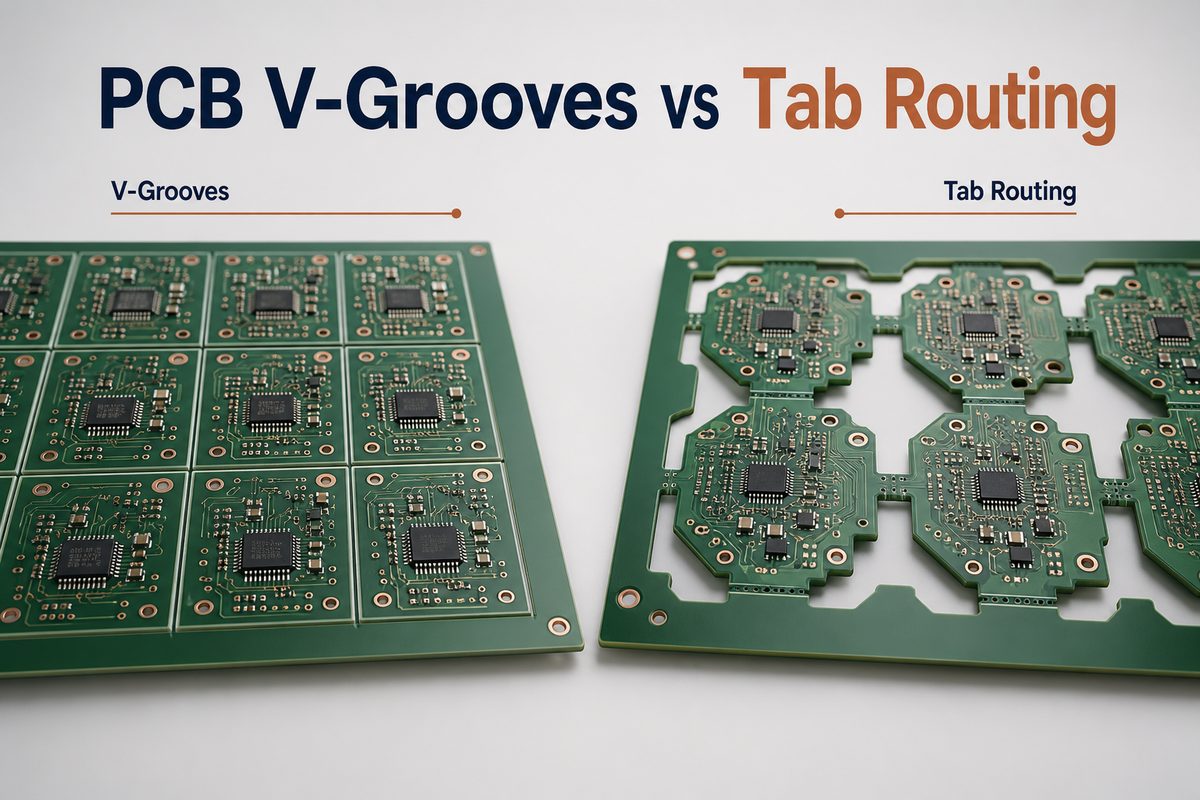
PCB V-grooves vs tab routing is mainly a choice between panel efficiency and geometric freedom. V-grooves are usually the simpler option when board boundaries form continuous straight lines. Tab routing is more suitable for curved or irregular outlines, local support points, and designs that cannot share a full straight separation line.
That rule is only the starting point. Component position, copper near the edge, acceptable breakaway stress, edge-finish requirements, routing clearance, assembly handling, and the planned depaneling process can all change the decision. This guide compares the two methods from the perspective of a PCB designer preparing a manufacturable panel.
What Are PCB V-Grooves and Tab Routing?
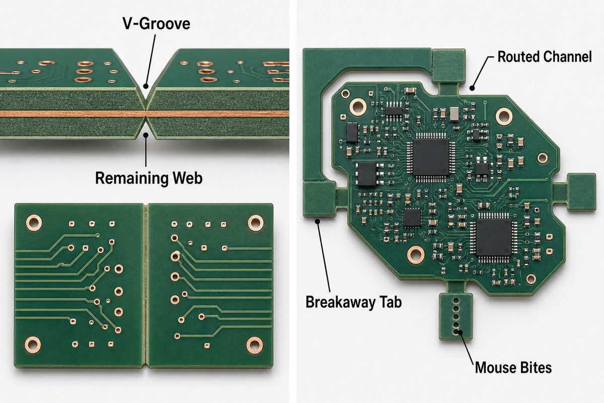
A V-groove, also called a V-score, is a shallow V-shaped cut made from both sides of a PCB panel along a straight separation line. A thin web of base material remains between the two cuts, holding the boards together during fabrication and assembly. The individual boards are separated later by bending or with a dedicated depaneling machine.
Tab routing uses a router to remove most of the material around each PCB outline while leaving selected bridges, or tabs, that keep the boards connected to the panel or rails. A tab can remain solid for machine cutting, or it can include a row of small holes known as mouse bites so it can be broken away more easily.
The two methods therefore create different panel structures:
- V-groove: continuous straight separation line, little or no gap between adjacent boards, and a continuous residual web.
- Tab routing: routed clearance around the outline, with support only at chosen tab locations.
- Mouse-bite tab: a routed tab weakened by drilled perforations; it is a variation of tab routing, not a separate outline-cutting process.
PCB V-Grooves vs Tab Routing: Quick Comparison
V-grooves favor regular arrays and fast straight-line separation. Tab routing favors outline freedom and controlled support placement. The correct choice depends on the complete panel, not just the shape of one board.
| Decision Factor | V-Groove | Tab Routing |
|---|---|---|
| Board outline | Best for straight, aligned boundaries | Supports curved, round, and irregular outlines |
| Space between boards | Often zero along the scored edge | Requires a router path around the outline |
| Support location | Continuous along the score line | Placed at selected tabs |
| Separation | Bending or V-score depaneling equipment | Breaking perforated tabs or cutting solid tabs |
| Finished edge | Straight scored edge with a small fracture zone | Routed edge with local tab witness marks |
| Typical reason to choose | Material use and production efficiency | Outline flexibility and local stress control |
Neither method guarantees a perfect edge without a suitable depaneling process. A poorly supported routed panel can flex during assembly, while an incorrectly separated V-scored panel can transfer bending force into components. Panel stiffness, tab locations, separation equipment, and handling instructions must be considered together.
When Should You Use V-Grooves?
Use V-grooves when the PCB boundaries can be arranged as uninterrupted straight lines across the panel and the assembly can tolerate the planned separation method. This is common for rectangular boards placed in a regular matrix.
V-grooves are attractive when:
- adjacent boards have straight and aligned edges;
- high panel utilization is important because no router channel is needed between scored edges;
- the production line needs fast, repeatable depaneling;
- components, pads, traces, and mounting holes can remain outside the required score-line clearance;
- the final product accepts the dimensional and cosmetic character of a scored edge.
Do not select V-scoring only because the board looks rectangular. A connector that overhangs the edge, a tall component beside the score, a fragile ceramic component, or copper that enters the scoring zone may make that edge unsuitable. The direction of bending during separation also matters.
When Should You Use Tab Routing?
Use tab routing when the outline cannot be separated by a continuous straight cut or when the panel needs support at selected locations. The router can follow arcs, cutouts, and irregular profiles while leaving controlled bridges between the board and the surrounding material.
Tab routing is usually the stronger candidate when:
- the PCB is round, curved, L-shaped, notched, or otherwise irregular;
- edge connectors, antennas, LEDs, switches, or mechanical features interrupt a possible score line;
- the separation load should be limited to chosen parts of the perimeter;
- most of the final edge must be router-finished rather than fractured;
- a board needs dedicated rails, spacing, or component overhang clearance.
Tab routing consumes more panel area because the router needs a path, and each tab must be accessible for cutting or breaking. It can also leave visible nubs where the tabs were removed. Those tradeoffs should be weighed against the flexibility it provides.
PCB V Groove Specifications
The practical intent behind a search for pcb v groove specifications is to know what must be defined before a panel is released. There is no universal score geometry for every board thickness, laminate, scoring machine, and finished-edge requirement. The fabricator should confirm the dimensions.
A V-groove drawing or fabrication note should address:
- Score centerline: show the exact line and make sure it continues across the full panel in a direction the scoring machine can process.
- Remaining web: define or approve the material left between the top and bottom cuts. Too much material makes separation difficult; too little weakens the panel.
- Score angle and tolerance: use the manufacturer’s supported cutter geometry and inspection method.
- Board thickness and material: scoring behavior changes with thickness and laminate construction.
- Copper and component clearance: keep conductors, pads, holes, and components outside the confirmed scoring and bending zone.
- Depaneling direction: document how the assembly will be supported and which way the board will be separated.
A commonly quoted remaining-web ratio is only a starting reference. It should not be copied into a new design without checking the selected supplier’s capability and the planned separation equipment. The same caution applies to score angle, board thickness limits, and component clearances.
PCB Tab Routing Guidelines
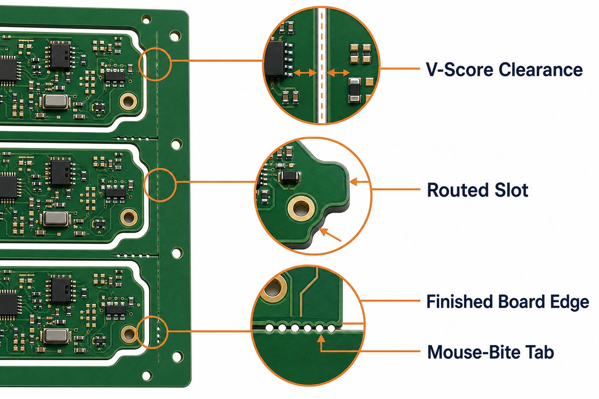
Good pcb tab routing guidelines start with panel stability. Tabs should hold the array flat through printing, placement, reflow, inspection, and handling without making final separation unnecessarily difficult.
Review the following before release:
- Tab count and position: distribute support so the board does not twist, sag, or vibrate, especially around heavy components.
- Tab width: use enough material for process stability, but avoid a bridge that requires excessive cutting force.
- Router access: leave a continuous cutter path and consider the router diameter at corners and narrow gaps.
- Edge keepout: keep copper, pads, brittle components, and sensitive features away from the tab-removal zone.
- Tab removal method: state whether tabs will be broken, cut with a hand tool, milled, or separated by a fixture.
- Residual nub allowance: decide whether a witness mark is acceptable or whether secondary edge finishing is required.
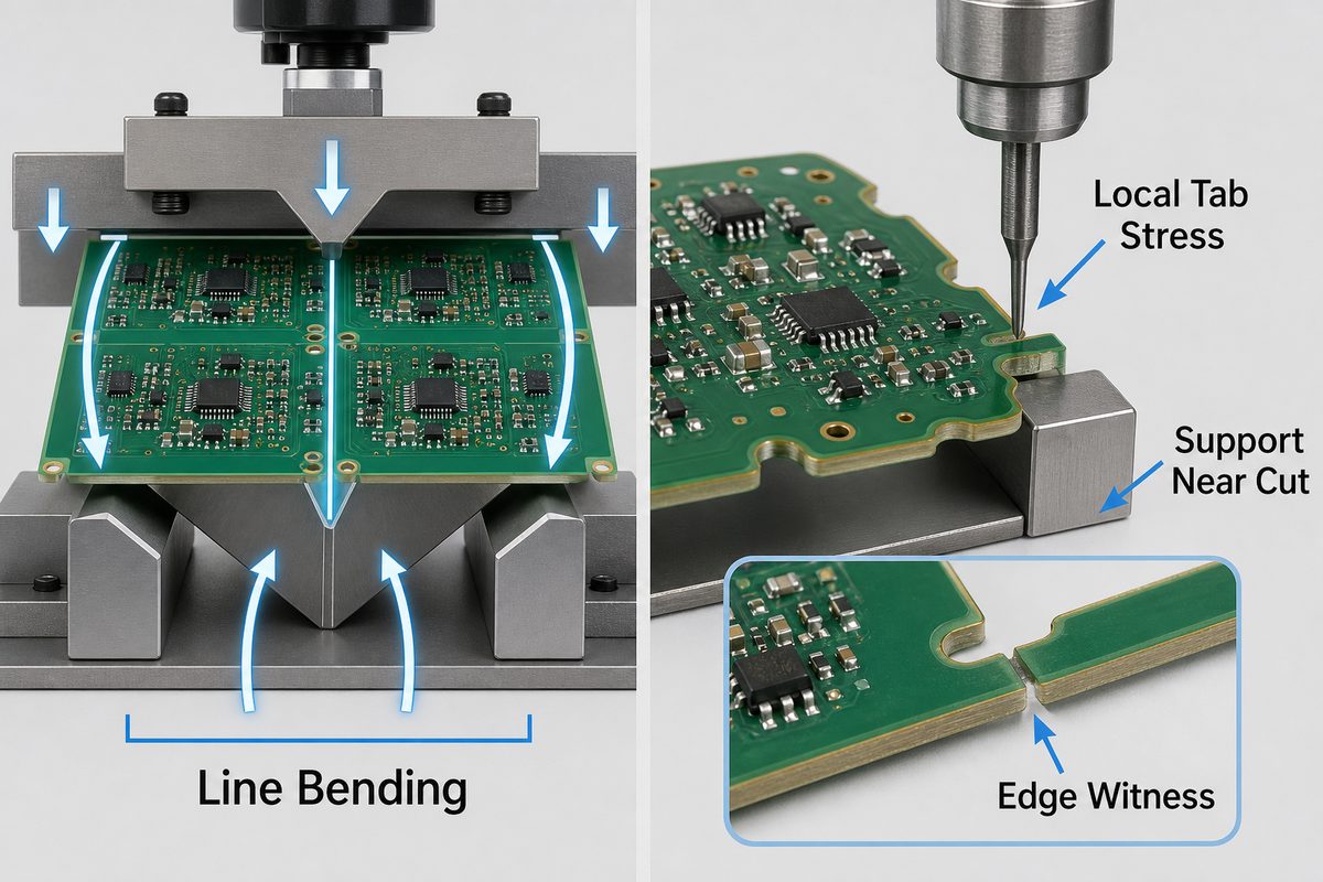
Tab placement should reflect how the board will be supported during removal. Pulling a tab away from an unsupported corner can twist the PCB. A better process constrains the assembly close to the tab and uses a repeatable cutting or breaking direction.
How Do Board Shape and Edge Components Affect the Choice?
Board geometry is the first filter, but edge-mounted parts often decide the final method. A straight outline may still need routing if a connector lip, antenna keepout, LED, switch, castellation, or mounting feature occupies the score path.
Use this selection sequence:
- Trace every separation boundary. If any required boundary is curved or cannot continue across the panel, route that boundary.
- Mark component envelopes. Include the body, solder joint, overhang, insertion tooling, and keepout—not just the land pattern.
- Mark fragile parts. MLCCs, glass components, ceramic packages, BGA assemblies, and large solder joints deserve extra attention near a flexing edge.
- Check the finished enclosure interface. A local tab mark may be unacceptable on a sliding, sealing, cosmetic, or connector-mating edge.
- Check production access. Rails, tooling holes, fiducials, clamps, conveyors, and depaneling blades all need space.
A hybrid layout may keep V-grooves on clean straight sides and use routed tabs around interrupted or shaped edges. That solution is often better than forcing one method across the entire panel.
How Do Separation Stress and Edge Quality Differ?
V-groove separation bends a continuous line until the residual web fractures. Tab routing limits the connection to local bridges, but the stress at each bridge can still be high if a tab is twisted or torn. The actual strain seen by a component depends on support distance, board thickness, copper distribution, separation direction, and tooling.
To reduce damage risk:
- support the PCB close to the separation line or tab;
- use a depaneling tool rather than uncontrolled hand bending for sensitive assemblies;
- move brittle or large components away from high-strain edge zones;
- avoid placing a score line through dense copper or immediately beside plated holes;
- inspect solder joints and components after the actual production separation process, not only on an unassembled panel.
Edge quality also has two meanings. Routing creates a machined outline, but tab removal leaves local witness marks. V-scoring creates a straight separation edge, but part of that edge is fractured rather than fully machined. If the PCB must slide into a slot, seal against a gasket, expose a cosmetic edge, or meet a tight profile tolerance, identify the critical edge on the drawing and agree on the finishing method.
PCB Mouse Bites Dimensions
Searches for pcb mouse bites dimensions often imply that one hole pattern should work everywhere. In practice, the perforation is a controlled weak point, and its geometry must match the board thickness, material, tab width, required panel strength, and acceptable post-break edge.
Confirm these items with the PCB manufacturer:
- hole diameter and number of holes per tab;
- hole pitch and the amount of material left between holes;
- the location of the hole row relative to the finished board outline;
- tab width, tab count, and spacing around the board;
- copper, component, and plated-feature clearance;
- acceptable protrusion after the tab is broken away.
Moving the perforation line outward can leave a larger nub. Moving it inward can remove material from the nominal board edge. The drawing should identify the finished profile and the intended break line clearly enough that the manufacturer does not need to infer which result is acceptable.
Can V-Grooves and Tab Routing Be Combined?
Yes. A panel can use V-grooves on aligned straight boundaries and routed tabs on irregular or interrupted boundaries, provided the combined structure remains stable and both processes are supported by the manufacturer.
A hybrid approach is useful when:
- rectangular boards share long straight edges but include one shaped side;
- one panel axis can be scored while the other needs component or connector clearance;
- routed openings are needed around overhanging parts while the remaining boundaries can stay tightly nested;
- the assembly line wants rails and local breakaway features without giving up all scored-edge material efficiency.
Do not assume a mixed panel is automatically better. It adds process instructions and can create weak transitions where routed features meet score lines. The panel should be reviewed as a single mechanical structure.
What Should Be Included in the Panel Drawing?
The panel drawing should remove ambiguity about finished profile, separation features, assembly rails, and process ownership. If the supplier will create the production panel, provide the single-board data plus the assembly constraints and ask for the proposed panel drawing for approval.
Include or confirm:
- finished board outline and panel outline;
- array count, orientation, and board-to-board spacing;
- V-score centerlines and routed paths on the designated mechanical layer;
- tab locations and whether each tab is solid or perforated;
- rails, tooling holes, global fiducials, local fiducials, and conveyor direction;
- component overhangs and keepout regions;
- critical edge tolerances and areas that cannot show tab remnants;
- depaneling method and any assembly-side support requirement.
These details connect the comparison to the broader set of pcb panelization methods. For more context on array construction, rails, tooling, and assembly handling, see our PCB panelization guide. Our guides to PCB depaneling, mouse-bite PCB design, and V-cut PCB depaneling cover the related processes in more detail.
FAQ About PCB V-Grooves and Tab Routing
Is V-grooving the same as routing a PCB outline?
No. V-grooving scores a straight separation line from both sides while leaving a continuous web. Routing removes material with a rotating cutter and can follow shaped outlines while leaving selected tabs.
Does tab routing always include mouse bites?
No. A routed tab can be solid and cut with a tool, or it can be perforated with mouse-bite holes for breakaway separation. The manufacturing drawing should state which tab type is required.
Which method uses less PCB material?
V-grooves usually use less space along aligned straight boundaries because adjacent boards can share the score line. Tab routing needs a cutter path, but it can sometimes nest irregular shapes efficiently. The complete panel yield should be compared rather than one gap dimension.
Which method is safer for components near the edge?
Neither is automatically safe. V-scoring creates bending along a line, while breaking a routed tab creates local stress. Component type, distance, board support, tab placement, and depaneling equipment determine the actual risk.
Can a V-groove stop in the middle of a panel?
Most conventional scoring processes require a straight line that runs across the panel. A stopped or curved separation feature should normally be routed, but the final construction must be confirmed with the selected manufacturer.
Who should create the final production panel?
The PCB or PCBA supplier often creates or adjusts the production panel because its equipment, rails, fiducials, process clearances, and depaneling method determine the final details. Designers should still provide the product constraints and approve the proposed panel.
How Can EBest Circuit Review Your PCB Panelization?
At EBest Circuit, we provide PCB fabrication and PCBA assembly support from prototype builds through production. Our engineering review can check board outline, score feasibility, routed-tab placement, component-to-edge conflicts, panel rails, tooling features, and the separation information needed for the selected assembly process.
Send your Gerber or ODB++ data, board thickness, stackup, BOM, component placement, required quantity, assembly method, and finished-edge requirements to sales@bestpcbs.com. If any component overhangs the board or any edge has a tight mechanical tolerance, identify it in the drawing. We will review whether PCB V-grooves vs tab routing, or a hybrid panel, is the better production approach for your project.
You may also like





Tags: pcb mouse bites dimensions, pcb panelization methods, pcb tab routing guidelines, pcb v groove specifications, PCB V-grooves vs tab routing