

Which is difference between metal core PCB and FR4? This article compares the structural characteristics, thermal performance, and applicable scenarios of metal core and FR4 PCBs, providing accurate selection guidance.
Are you troubled with these problems?
- FR4’s slow heat dissipation causes device throttling & 30% shorter LED lifespan?
- PCB thermal expansion cracks solder joints, compromising power module stability?
- Heat management delays high-power production, increasing cycle time & costs?
As a metal core PCB manufacturer, EBest Circuit (Best Technology) can provide service and solutions:
- Aluminum substrate: ≥2.0W/m·K thermal conductivity, cuts device junction temp, extends LED life by 50%.
- Copper-ceramic composite: Matches chip CTE, reduces thermal stress on solder joints.
- 48 hour rapid prototyping: Dedicated team cuts lead time by 40%, accelerates high-power mass production.
Welcome to contact us if you have any inquiry for MCPCB: sales@bestpcbs.com.
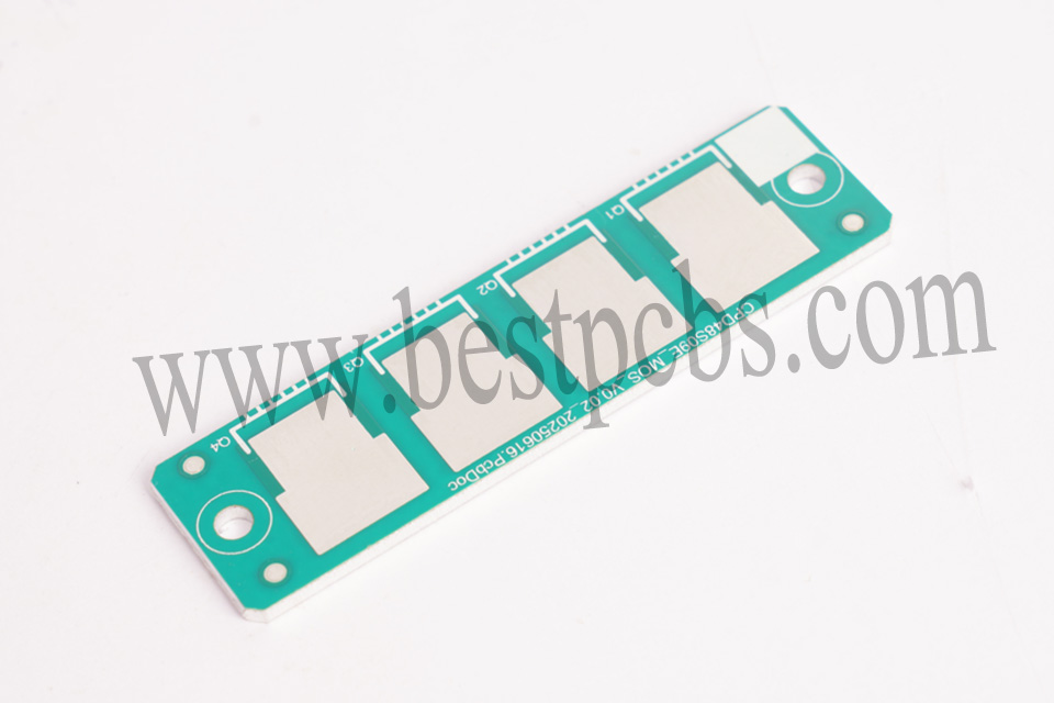
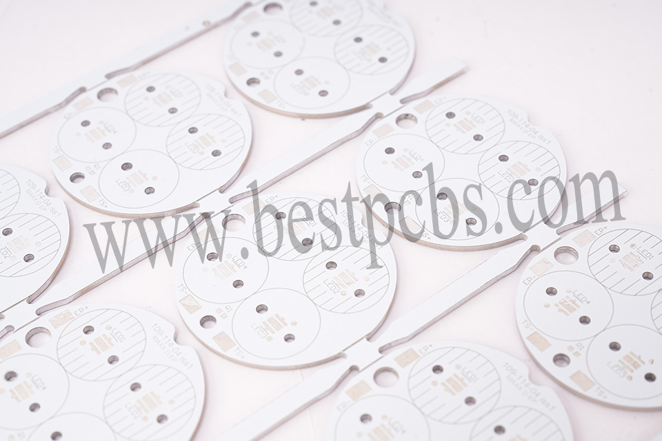
What Is a Metal Core PCB?
A Metal Core PCB (MCPCB) is a printed circuit board with a metal base layer, typically aluminum or copper, designed for efficient heat dissipation in high-power applications. Its three-layer structure consists of copper circuitry, dielectric insulation, and metal core, enabling superior thermal management.
This makes it ideal for LED lighting, automotive electronics, and industrial power systems. The metal core acts as a heat sink, transferring heat away from components to prevent overheating while maintaining electrical insulation through the dielectric layer. This design ensures reliable performance in high-temperature environments.
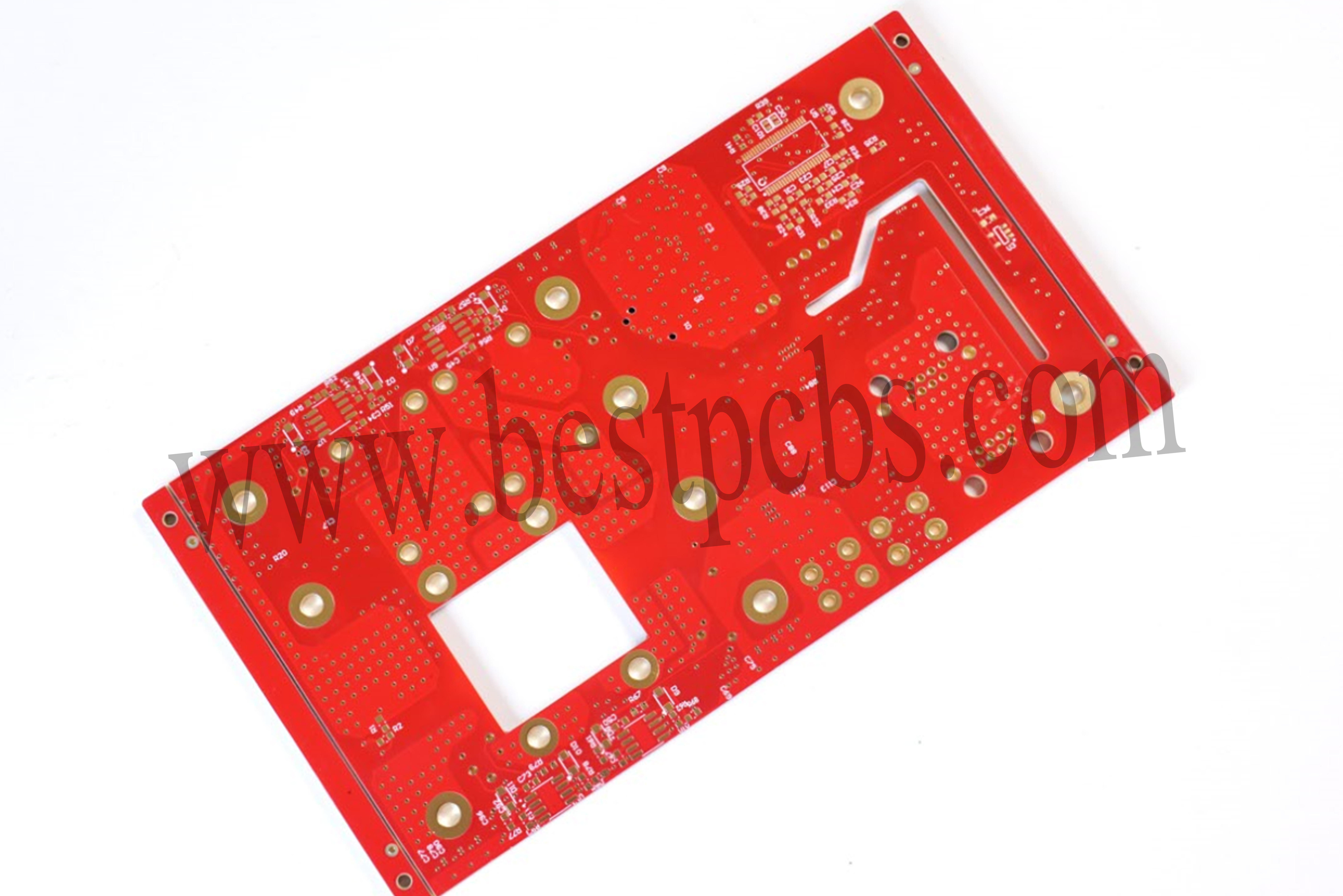
What Is a FR4 PCB?
FR4 PCB is a printed circuit board made from FR-4 material, a flame-retardant glass fiber reinforced epoxy resin composite widely used in electronics due to its excellent mechanical strength, electrical insulation, and thermal stability.
It serves as a reliable substrate for mounting components while ensuring dimensional stability under varying environmental conditions. The material’s UL94 V-0 flammability rating and cost-effectiveness make it the standard choice for most consumer electronics, industrial equipment, and communication devices.
What Is the Difference? Metal Core PCB vs FR4
Material Composition & Structure
- FR4 PCB: Manufactured from woven glass fiber impregnated with epoxy resin, this composite material offers insulation and mechanical strength. Its mature fabrication process supports multi-layer stacking for complex circuit designs, with copper traces plated on surfaces, ideal for standardized electronic module production.
- Metal Core PCB: Built with aluminum or copper substrates in a “sandwich” architecture (circuit layer-insulation layer-metal base), the metal layer provides thermal support. Aluminum substrates are lightweight and cost-effective, while copper substrates deliver superior thermal conductivity (>380W/m·K). Insulation layers often use thermal silicone or ceramic-filled materials to balance electrical isolation and heat conduction.
Thermal Performance
- FR4 PCB: Thermal conductivity ~0.3W/m·K, weak heat dissipation suitable for low-to-mid power applications. In LED modules or low-power supplies, external heatsinks are required to prevent thermal buildup that raises chip junction temperatures and shortens lifespan.
- Metal Core PCB: Thermal conductivity ranges from 1-380W/m·K (aluminum: 1-3W/m·K, copper: >380W/m·K), achieving 6-9 times higher efficiency than FR4. For example, in automotive LED headlights, copper substrates rapidly dissipate heat from IGBTs, preventing light decay or burnout.
CTE Matching
- FR4 PCB: Coefficient of Thermal Expansion (CTE) 12-24ppm/°C, significantly differing from copper’s 17ppm/°C, leading to delamination risks under thermal stress. Repeated thermal cycling may cause micro-cracks at FR4-copper interfaces, reducing electrical reliability.
- Metal Core PCB: CTE closely matches copper (e.g., aluminum: 24ppm/°C), minimizing thermal cycling failure risks. The low CTE differential ensures stable electrical connections in high-reliability applications like aerospace or industrial control systems.
Mechanical Strength & Environmental Adaptability
- FR4 PCB: Flexural strength ~480MPa, suitable for consumer electronics but prone to deformation under high temperature/pressure. While stable in everyday devices, it risks board fracture in vibration-heavy industrial environments.
- Metal Core PCB: Metal substrates enhance rigidity, vibration/impact resistance, and suitability for extreme conditions like automotive electronics or industrial equipment. For instance, in new energy vehicle motor controllers, aluminum substrates withstand high-frequency vibrations and thermal shocks, ensuring circuit stability.
Electrical Performance
- CDielectric constant 4.0-4.8, loss tangent 0.01-0.02, optimal for mid-to-low frequency signal transmission. Enables low-loss signal routing in communication devices, supporting high-frequency/high-speed designs.
- Metal Core PCB: High-frequency performance depends on insulation layer design. While typically prioritized for thermal management, electrical performance slightly lags FR4. Optimized insulation materials (e.g., low-dielectric polymers) can balance high-frequency signal integrity with thermal efficiency.
Cost & Processing
- FR4 PCB: Low cost, easy processing, and compatibility with complex multi-layer designs. Mass-produced by standard PCB factories at 1/3 to 1/5 the cost of metal core PCBs, ideal for large-scale consumer electronics.
- Metal Core PCB: Higher costs due to specialized processing (e.g., metal substrate etching, precision drilling) and single/simple multi-layer structures. Despite elevated per-unit costs, long-term thermal management benefits reduce system maintenance expenses.
Application Scenarios
- FR4 PCB: Dominates general-purpose fields like consumer electronics, communication devices, and home appliances (e.g., smartphone motherboards, router PCBs), leveraging low cost and mature processes for rapid iteration.
- Metal Core PCB: Targets high-power, thermally demanding scenarios such as LED lighting, power modules, automotive electronics, and industrial equipment (e.g., streetlight drivers, EV battery management systems), optimizing thermal management to enhance device reliability.
Why Are Metal Core PCBs Better at Dissipating Heat than FR4 PCBs?
Reasons why MCPCB better at dissipating heat than FR4 PCB:
- Direct Thermal Path via Metal Substrate: Aluminum/copper substrates in Metal Core PCBs create a vertical thermal channel from the chip through the insulating layer to the metal base. This bypasses FR4’s multi-layer dielectric thermal resistance stack-up, reducing thermal resistance by 60-90%. For example, in IGBT modules, copper-based PCBs can lower junction temperatures by 20-30°C, directly extending device lifespan.
- Optimized Insulation Layer Materials: Metal Core PCBs use thermally conductive silicones, ceramic fillers (e.g., AlN), or nano-composites as insulating layers. These materials balance electrical isolation with high thermal conductivity (5-20W/m·K for AlN-filled layers vs. FR4’s 0.3W/m·K), creating a “thermal short-circuit” effect for rapid heat transfer.
- Active Thermal Structure Design: Metal substrates can be machined with fins, thermal via arrays, or embedded heat pipes to actively expand surface area. In LED streetlights, aluminum substrates with radial fins increase heat dissipation area by 300%, enabling passive air cooling without additional fans.
- Thermal-Mechanical Stability: Metal’s high rigidity minimizes thermal deformation impacts on circuits. In automotive power systems, aluminum substrates exhibit <0.1% warpage across -40°C to 125°C cycles, compared to FR4’s >0.5% deformation that risks solder joint fatigue.
- System-Level Thermal Integration: Metal Core PCBs integrate directly with enclosures/heatsinks to form a unified thermal management chain. In 5G base station power modules, copper substrates bond with aluminum chassis for large-area passive cooling, reducing reliance on active cooling components and lowering system complexity/cost.
Why is Metal Core PCB More Suitable for High-Power Application Than FR4 PCB?
Superior Thermal Conductivity Materials
- Metal core PCBs utilize copper (385 W/mK), aluminum (200 W/mK), or steel alloys with thermal conductivity 50-1000 times higher than FR4 (0.4 W/mK). This allows rapid heat dissipation from components, preventing thermal buildup-induced performance degradation or failure. For example, in 1000A automotive IGBT modules, copper substrates limit temperature rise to ≤30℃, while FR4 may trigger thermal protection due to localized overheating.
3D Heat Conduction Architecture
- Thermal via arrays (0.1mm micro-vias at 100 holes/cm² density), embedded copper blocks (0.5-2mm thick), and metal backplate heat sinks form a tiered heat conduction path: component → thermal vias → substrate → external heatsink. This vertical heat transfer achieves 3-5 times higher efficiency than FR4’s planar heat spreading, ideal for high-power-density scenarios like LED streetlights and 5G base station PA modules.
Enhanced Heat Diffusion & Thermal Uniformity
- High thermal diffusivity of metals (e.g., aluminum at 97 mm²/s) enables heat to spread evenly across the substrate within 0.1 seconds, avoiding localized hotspots that plague FR4 (thermal diffusivity: 0.3 mm²/s). During 150℃ thermal shock tests, metal core PCBs exhibit stable temperature profiles, whereas FR4 shows stepwise heating that risks component thermal stress cracking.
Low-Resistance Heat Dissipation Path
- Direct contact between component pads and the metal substrate via high-conductivity solder (e.g., SnAgCu) achieves thermal resistance as low as 0.1℃/W—significantly lower than FR4’s insulation layer resistance (>10℃/W). This direct path minimizes interlayer thermal resistance accumulation, ensuring stable high-power operation.
High-Temperature Durability & Long-Term Reliability
- Metal substrates withstand temperatures >300℃ (e.g., copper), while FR4 softens above 130℃, risking delamination or solder joint failure. Metal core PCBs pass 1000-hour 85℃/85%RH CAF (Conductive Anodic Filament) tests for corrosion resistance, outperforming FR4’s 500-hour limit and reducing long-term failure rates.
Extreme Environment Adaptability
- In aerospace and deep-sea applications, metal core PCBs endure -55℃ to 125℃ temperature swings, high pressure, and salt spray without degradation. FR4, prone to moisture absorption and insulation breakdown, fails in such conditions—e.g., satellite power modules rely on steel alloy substrates for vacuum stability.
Process Optimization for Performance Guarantee
- Ceramic-filled epoxy insulation (3-5 W/mK thermal conductivity), immersion gold (ENIG)/OSP surface finishes, and AOI/X-ray automated inspections ensure heat dissipation reliability. High-conductivity insulation outperforms FR4 by 10x, while surface treatments enhance solder joint reliability and oxidation resistance. Automated inspections verify defect-free interlayer connections.
How Does Cost Difference between FR4 and Metal Core PCB?
The unit price of a standard double-sided FR4 PCB (1.6mm thickness) is approximately $2-$5 per piece. Leveraging a mature supply chain and the low-cost advantages of glass fiber substrates, it is suitable for large-scale mass production, with the unit price for an order of 10,000 pieces being reduced to $0.5 per piece. Metal core PCBs (MCPCBs) of the same size cost $15-$50 per piece, 7-10 times the cost of FR4.
This is mainly due to the high price of aluminum/copper core substrates (approximately $10-$30/㎡, 3-5 times the cost of FR4 substrates), the need for specialized surface treatment processes such as drilling and anodizing (which increase manufacturing costs by 30%-50%), and the difficulty in allocating processing losses in small-batch production, limiting the room for cost reduction.
How to Choose between Metal Core PCB and FR4 PCB?
Clarify Power Requirements & Thermal Constraints
- High-power scenarios (≥50W/cm² heat density): Choose metal core PCB (aluminum/copper-based) for 6-9x higher thermal conductivity (1-380W/m·K vs. FR4’s 0.3W/m·K), preventing overheating in LED lighting, power modules, or automotive IGBTs.
- Low-power scenarios (<20W/cm²): Optimize for FR4 due to lower cost and mature fabrication, ideal for consumer electronics and home appliances.
Evaluate Environmental Resilience
- Extreme conditions (high temp/vibration/humidity): Metal core PCB’s rigid metal base (2-3x stronger than FR4) withstands shocks in automotive power systems or industrial drives.
- Standard environments (indoor/low-vibration): FR4 suffices for basic mechanical strength in routers or phone motherboards.
Balance Cost & Long-Term Benefits
- Budget-sensitive/mass production: FR4 wins with low material costs, complex multi-layer support, and quick scaling.
- High reliability/longevity focus: Metal core PCB reduces secondary cooling costs (e.g., heat sinks/fans) and extends device life, justifying its higher unit cost in 5G power supplies.
Match Electrical & Signal Requirements
- High-frequency applications (≥1GHz): FR4’s superior dielectric constant (4.0-4.8) and loss tangent (0.01-0.02) suit fine-line RF designs.
- Thermal-priority scenarios (e.g., LED drivers): Metal core PCB balances heat dissipation with optimized insulators like thermal silicone.
Consider Thermal Expansion Compatibility
- Frequent thermal cycling (outdoor/industrial control): Metal core’s CTE (e.g., aluminum: 24ppm/°C) aligns with copper traces (17ppm/°C), minimizing interface stress and delamination risk.
- Stable thermal environments (indoor): FR4 works with stress-relief designs (e.g., thermal buffer layers) at lower cost.
Factor in Design Complexity & Manufacturability
- Complex multi-layer/high-density interconnects: FR4’s mature processes support intricate stacking and fine-pitch routing.
- Simple/single-layer thermal-centric designs: Metal core PCB’s streamlined structure reduces manufacturing complexity, ideal for cost-sensitive thermal applications.
Assess Sustainability & Recycling Potential
- Eco-conscious projects: FR4’s glass-fiber/epoxy composition is recyclable via specialized processes, while metal core PCBs (aluminum/copper) offer higher material recovery rates, aligning with circular economy goals.
Why Choose EBest Circuit (Best Technology) as Your Metal Core PCB Manufacturer?
Reasons why choose us as metal core PCB manufacturer:
- Mature Process Library & Parameterized Design Support: Leverage proven process libraries and parameterized design templates for single-layer to multi-layer metal-core substrates (aluminum/copper/iron-based), reducing trial-and-error costs by 30% and accelerating time-to-market for rapid iteration projects.
- Dual Certification Compliance Guarantee: Meet stringent medical (ISO 13485) and automotive (IATF 16949) industry standards with dual certifications, shortening product launch cycles by 2-4 weeks and minimizing compliance risks for swift project validation.
- 24-Hour Rapid Prototyping Delivery: Enable same-day design validation closure and next-day physical prototype delivery for urgent needs, supporting fast design feasibility verification and market entry acceleration.
- Full-Process 12-Step SPC Quality Control: Implement batch-specific CPK≥1.33 testing across thickness, thermal conductivity, and insulation resistance, ensuring ≥99.5% yield to minimize rework losses and provide reliable mass production assurance.
- Transparent Tiered Pricing System: Eliminate hidden costs like mold/engineering fees, optimize metal material costs by 30% for bulk orders, and offer clear budgeting support for precise project cost management.
- One-Stop Full-Process Service Chain: Cover end-to-end workflows from design support, prototyping, mass production, surface finishing (ENIG/OSP), to assembly testing, cutting multi-vendor coordination costs by 50% and freeing focus for core design optimization.
- Free DFM Design Optimization: Proactively identify process risks (e.g., thermal stress, etching defects) to optimize layout and material selection, lowering production costs by 20% and enhancing manufacturability for seamless design-to-manufacturing transition.
- Customized Thermal Management Solutions: Utilize high thermal conductivity materials (aluminum ≥2.0W/m·K, copper ≥380W/m·K) to design thermal vias, integrate heat sinks, and perform thermal simulations, ensuring ≤20℃ temperature rise in high-power scenarios for enhanced product reliability.
Welcome to contact us if you have any request for metal core PCBs: sales@bestpcbs.com.
Tags: MCPCB, Metal Core PCB, Metal Core PCB vs FR4