

What is thermal substrates MCPCB? This guide explores its thermal properties, specifications, benefits, applications, material selection, design strategies, and supplier criteria for optimized thermal management.
Why do traditional PCBs always overheat and fail in high-power scenarios?
How to balance heat dissipation performance and production costs?
How to avoid thermal stress tearing in multi-layer complex designs?
EBest Circuit (Best Technology) Can Provide:
- Precise thermal conductivity design – Customized metal stacking (copper/aluminum hybrid substrate) + high thermal conductivity insulation layer (8W/m·K), reducing temperature difference by 40%.
- Cost-optimized architecture – Partitioned heat dissipation solution: copper in critical areas and aluminum in non-critical areas, saving 30%+ in costs.
- Stress-resistant process – Nano-ceramic filling + CTE matching technology, passed 1,000 -40°C~125°C cycle tests, zero delamination.
Feel free to contact EBest Circuit (Best Technology) if you have any request for MCPCB: sales@bestpcbs.com.
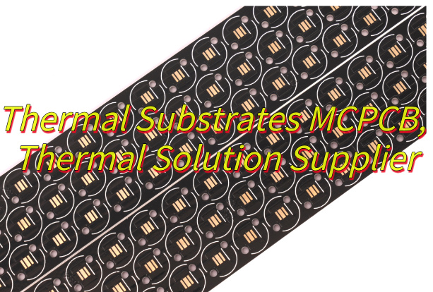
What Is Thermal Substrates MCPCB?
Thermal Substrate MCPCB, short for Metal Core Printed Circuit Board, is a specialized type of printed circuit board designed primarily to enhance heat dissipation in electronic systems by integrating a thermally conductive metal base, such as aluminum or copper, which efficiently transfers heat away from mounted components to prevent overheating and ensure stability.
Its layered construction typically comprises a copper circuit layer for electrical routing, an insulating dielectric layer made from polymer materials filled with ceramics to balance electrical isolation and thermal conductivity, and the metal core that acts as a heat spreader, facilitating faster thermal transfer than standard alternatives.
Thermal Substrates MCPCB Specifications
| Parameter Category | Typical Specification Range | Technical Notes |
| Metal Base Material | Aluminum (Al) / Copper (Cu) | Al base: 1.3-2.2 W/m·K thermal conductivity; Cu base: ~400 W/m·K (higher cost) |
| Insulating Layer Material | Ceramic-filled epoxy resin/Polyimide | Thermal conductivity: 1.3-8 W/m·K; Operating range: -40°C~140°C |
| Copper Foil Thickness | 1oz~3oz (35~105μm) | 3oz thick copper for high-current applications; Requires CTE matching |
| Thermal Resistance (θ) | 0.5~5.0°C·cm²/W | 1mm Aluminum substrate: ~1.5°C·cm²/W (increases with insulating layer thickness) |
| Max Operating Temperature | 105°C~140°C | Sustained exposure >105°C accelerates insulating layer aging |
| Dielectric Strength | 2kV~4kV (AC) | 1mm insulation thickness withstands 2.5kV AC |
| Surface Finish | HASL/ENIG/OSP | ENIG recommended for high-frequency applications (reduced signal loss) |
| Machining Tolerance | ±0.1mm (contour)/±0.05mm (drilling) | Laser cutting: ±0.02mm precision (increases cost by ~50%) |
| RoHS Compliance | IEC 62321 Standard | Lead content <1000ppm; Cadmium <100ppm |
Thermal Substrates MCPCB Stackup
Typical Stackup Configuration (Bottom to Top):
1. Metal Base Layer (Heat Dissipation Backbone)
- Material: Aluminum (1-2.5W/m·K) or Copper (3-4W/m·K)
- Role: Directly transfers heat from components to external heat sinks, reducing junction temperature by 30-50% vs. FR4.
2. Thermal Dielectric Layer (Critical Heat Path)
- Material: Ceramic-filled epoxy (0.8-3W/m·K)
- Role: Bridges electrical insulation and thermal conductivity, overcoming traditional 0.3W/m·K limits. Thickness typically 50-150μm.
3. Circuit Layer (Functional & Thermal Optimization)
- Copper Thickness: 1oz (35μm) for low power; ≥2oz (70μm+) for high current
- Role: Thick copper reduces I²R losses, minimizing self-heating in traces.
What Are Advantages of Thermal Substrates PCB?
- High-Efficiency Cooling – Metal base conducts heat 5-10x faster than standard PCBs, keeping components 30-50% cooler.
- Enhanced Reliability – Reduces thermal stress, doubling or tripling the lifespan of LEDs, power semiconductors, and high-current devices.
- Space-Saving Design – Built-in metal heatsink eliminates bulky external cooling systems, ideal for compact electronics like automotive modules.
- High Current Handling – Supports thick copper traces (2oz+) to safely manage currents over 100A without overheating.
- Dimensional Stability – Low thermal expansion minimizes warping, ensuring reliability in multi-layer or high-temperature environments.
What Are Applications of Thermal Substrates PCB?
- High-Power LED Lighting – Ensures stable operation of COB/LED modules by dissipating heat directly through metal cores, preventing lumen depreciation.
- Automotive Electronics – Critical for powertrains, ECUs, and battery management systems operating in high-temperature environments without active cooling.
- Industrial Power Modules – Supports VFDs, motor drives, and inverters requiring efficient heat removal from IGBTs/MOSFETs under heavy loads.
- Telecom Infrastructure – Enables compact RF amplifiers and base station components to handle high frequencies without thermal throttling.
- Consumer Electronics – Used in gaming consoles, laptop chargers, and high-end audio amplifiers where space is limited but heat generation is high.
How to Choose the Material of Thermal Substrate MCPCB?
Thermal Substrate MCPCB Material Selection Guide
Power Density
- High Power (>5W/cm²): Choose copper base (3-4W/m·K) for superior heat spreading.
- Moderate Power: Aluminum base (1-2.5W/m·K) balances cost and performance.
Cost Sensitivity
- Budget-Critical: Aluminum substrates cost 20-30% less than copper.
- Performance-Priority: Copper justifies premium for extreme thermal demands.
Environmental Conditions
- High Humidity/Corrosion Risk: Anodized aluminum or nickel-plated copper.
- Extreme Heat (≥150℃): Copper with high-temp dielectric (e.g., polyimide).
Space Constraints
- Ultra-Thin Designs: Aluminum (0.8mm) enables compact heat dissipation.
- Multi-Layer Needs: Copper’s rigidity supports complex stackups without warping.
Reliability Requirements
- Automotive/Aerospace: Copper with low-CTE dielectric minimizes thermal cycling stress.
- Consumer Electronics: Aluminum meets standard lifespan needs at lower cost.
Quick Decision Methods
- Cost > Performance: Aluminum + standard dielectric.
- Performance > Cost: Copper + ceramic-filled dielectric.
- Harsh Environments: Copper + high-temp insulation (polyimide/benzocyclobutene).
How to Design Thermal Substrate MCPCB for High Power Applications?
High-Power MCPCB Thermal Design Guide
1. Base Material Selection
- Use copper substrate (3-4W/m·K) for power densities >5W/cm². Aluminum (1-2.5W/m·K) suits moderate loads.
2. Layer Stackup Priority
- Place metal base layer directly below high-power components to form a vertical heat path. Keep dielectric layer thickness ≤100μm.
3. Copper Trace Optimization
- Use 3oz (105μm) copper for all high-current traces (>50A). Widen traces by 2x near MOSFETs/IGBTs.
- Avoid sharp bends in power traces to reduce resistance.
4. Thermal Via Strategy
- Fill 0.5mm diameter vias under hot components with copper. Space vias 1mm apart in a grid pattern.
- Connect vias directly to the metal base layer.
5. Component Layout Rules
- Center power devices over the metal core. Maintain ≥2mm spacing between high-power components.
- Orient heat-sensitive parts (e.g., capacitors) away from thermal zones.
6. Reserved Cooling Space
- Allocate 40% of board area as unpopulated “thermal zones” directly above the metal base.
- Use solder mask removal in these zones to maximize metal exposure.
7. Validation Protocol
- Perform thermal imaging at 120% rated load to identify hotspots.
- Measure component junction temperatures – must stay ≤85℃ for reliable operation.
How to Select A MCPCB Thermal Solution Supplier?
Methods about how to select a MCPCB thermal solution supplier:
- Technical Expertise: Verify experience in high-power applications (e.g., LED, automotive, industrial). Ask for case studies showing thermal performance data.
- Material & Process Control: Ensure suppliers use certified materials (e.g., ISO 9001 for dielectric layers) and have in-house thermal conductivity testing.
- Prototyping Capability: Prioritize suppliers offering free/low-cost prototypes with thermal imaging reports to validate design feasibility.
- Thermal Simulation Support: Choose suppliers providing CFD (Computational Fluid Dynamics) analysis to predict heat distribution before production.
- Quality Assurance: Check for IPC-6012/6013 compliance and ask for third-party test reports (e.g., thermal resistance, dielectric breakdown).
- Lead Time & Scalability: Confirm standard lead times (ideally ≤2 weeks for prototypes) and capacity to scale to 10K+ units monthly.
- Cost Transparency: Request itemized quotes separating material, fabrication, and testing costs. Avoid suppliers with hidden tooling fees.
- Post-Production Support: Ensure suppliers offer failure analysis and warranty coverage (minimum 1 year for thermal performance defects).
Welcome to contact EBest Circuit (Best Technology) if you have any request for MCPCB thermal solution: sales@bestpcbs.com.
Tags: MCPCB, Thermal Substrates MCPCB