Looking for metal core board thermal solution? This guide explores materials, benefits, finishing options, and EBest Circuit (Best Technology)’s turnkey manufacturing expertise.
- Insufficient heat dissipation shortens component life?
- Unstable circuit performance in high temperature environment?
- Traditional PCB prototyping cycle slows down product launch?
- Harsh environment causes corrosion failure of substrate?
EBest Circuit (Best Technology) Can Provide:
- Extremely fast response: high-precision prototyping is completed in 24 hours, 3 times faster than the industry standard
- Thermal management expert: 2.0mm superconducting aluminum substrate, measured temperature reduction of 22-28ā
- Environmental adaptability: Passed 1000 hours of salt spray +85ā/85%RH dual aging test
- Reliability guarantee: Using Japanese original aluminum material, the number of thermal cycles exceeds 5000 times
Welcome to contact us now if you have any request for metal core board: sales@bestpcbs.com.
What Is Metal Core Board?
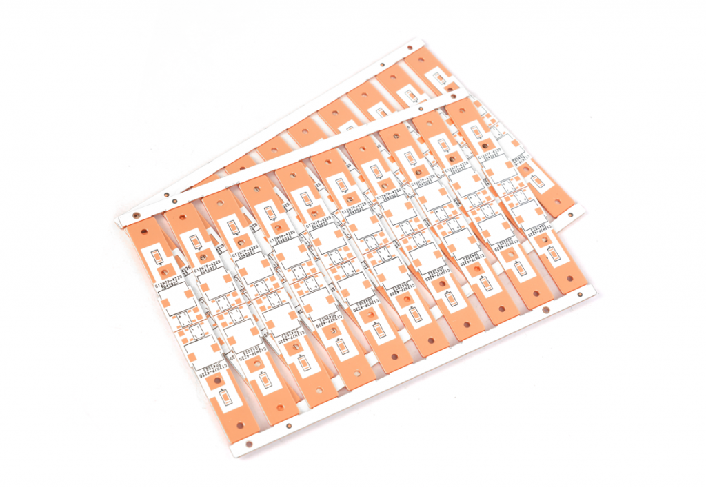
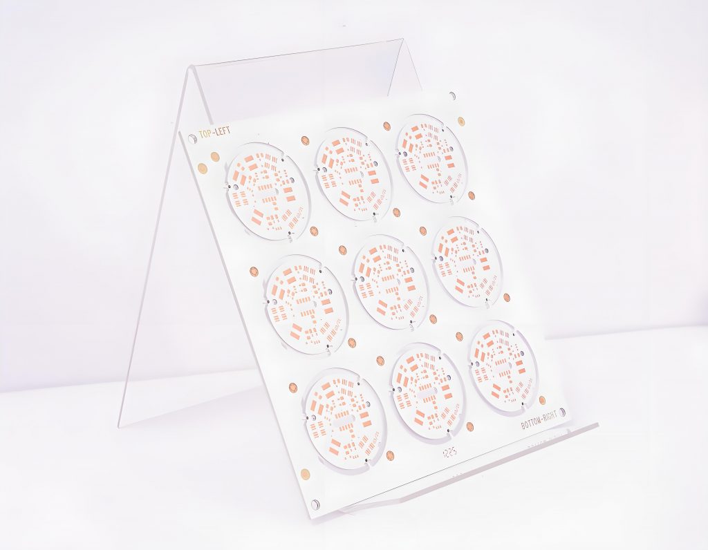
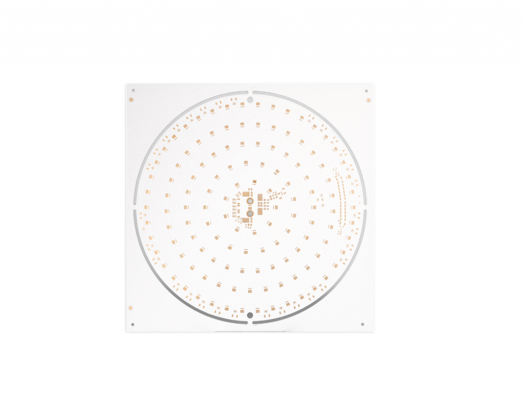
Metal Core Board (MCPCB) is a specialized printed circuit board built with a solid metal layer, typically aluminum or copper, forming its core foundation. This metal base acts as an integrated heat spreader. A thin, thermally conductive dielectric layer sits atop the metal, providing essential electrical insulation while simultaneously enabling efficient transfer of heat away from mounted electronic components directly into the metal core.
This construction offers superior heat dissipation compared to standard FR4 circuit boards. By rapidly drawing heat away from sensitive parts, metal core board prevents overheating-related failures and significantly enhances device reliability and lifespan. Consequently, it is extensively used in applications generating substantial heat, including high-power LED luminaires, power converters, motor controllers in vehicles, and RF power amplifiers, where effective thermal management is paramount for sustained operation.

Metal Core Circuit Board Materials and Thickness
Metal core circuit board materials and thickness specifications:
Core Materials:
- Aluminum (most common): Offers excellent thermal conductivity (1-3 W/mK) with good mechanical strength and cost-effectiveness.
- Copper: Provides superior thermal performance (380 W/mK) but at higher material cost and weight.
- Steel alloys: Used in specialized applications requiring structural rigidity or magnetic properties.
Dielectric Layer:
- Typically 50-200Ī¼m thick polymer-based insulation.
- Composed of epoxy resins with ceramic fillers for enhanced thermal transfer.
- Must maintain electrical isolation while allowing 1-3 W/mK thermal conductivity.
Standard Thickness Options:
- 1.0mm: Common for LED applications and general-purpose designs
- 1.5mm: Balanced option for medium-power applications
- 2.0mm-3.0mm: Used in high-power systems requiring maximum heat dissipation
Copper Cladding:
- Standard 1oz (35Ī¼m) to 4oz (140Ī¼m) copper foil
- Heavy copper options (up to 10oz) available for high-current traces
Thermal Performance Considerations:
- Thicker metal cores (ā„2mm) improve heat spreading capability
- Aluminum cores typically range from 0.8mm to 3.0mm thickness
- Copper cores often use 0.5mm to 2.0mm for weight optimization
Advantages of Metal Core Printed Circuit Board
Advantages of metal core PCBs:
- Thermal Management – Superior heat dissipation through metal substrate
- Power Handling – Supports higher current loads without overheating
- Component Protection – Reduces thermal stress on sensitive parts
- Structural Integrity – Enhanced mechanical strength and vibration resistance
- Space Efficiency – Compact design by integrating thermal solution
- Signal Quality – Improved EMI shielding for cleaner electrical performance
- Environmental Durability – Withstands harsh operating conditions reliably

Common Surface Treatments for Metal Core Printed Circuit Board
Surface Treatment Options for Metal Core Printed Circuit Boards (MCPCBs)
Hot Air Solder Leveling (HASL)
- Process: Immersion in molten solder (tin-lead or lead-free), followed by hot air blowing to remove excess solder.
- Benefits: Cost-effective, improves solderability, and provides a protective layer against oxidation.
- Considerations: May leave uneven surfaces; not ideal for fine-pitch components.
Organic Solderability Preservative (OSP)
- Process: Chemical application forms a thin, water-based organic layer on copper surfaces.
- Benefits: Flat finish, environmentally friendly, and compatible with fine-pitch SMT assembly.
- Considerations: Limited shelf life; requires controlled storage and handling.
Electroless Nickel Immersion Gold (ENIG)
- Process: Nickel layer deposited via chemical reaction, followed by immersion gold.
- Benefits: Excellent corrosion resistance, flat surface, and ideal for wire bonding or press-fit connectors.
- Considerations: Higher cost; nickel layer thickness must be carefully controlled.
Immersion Silver (ImAg)
- Process: Direct silver deposition on copper through displacement reaction.
- Benefits: High conductivity, suitable for high-frequency applications, and maintains solderability over time.
- Considerations: Susceptible to tarnishing in sulfurous environments; requires packaging in inert gas.
Immersion Tin (ImSn)
- Process: Tin layer formed via chemical displacement on copper.
- Benefits: Cost-effective, planar surface, and compatible with lead-free soldering.
- Considerations: Risk of tin whisker growth; not recommended for long-term storage.
Electroplated Nickel/Gold (Hard Gold)
- Process: Electroplating nickel followed by gold for durability.
- Benefits: Extremely wear-resistant, ideal for edge connectors or switches.
- Considerations: Expensive; gold thickness impacts cost and functionality.
Chemical Nickel Palladium Gold (ENEPIG)
- Process: Sequential deposition of nickel, palladium, and gold layers.
- Benefits: Enhanced reliability for multiple reflow cycles and harsh environments.
- Considerations: Complex process; higher cost than ENIG.
Anodizing (for Aluminum-Based MCPCBs)
- Process: Electrochemical oxidation to form a protective oxide layer.
- Benefits: Improves surface hardness, corrosion resistance, and thermal management.
- Considerations: Limits electrical conductivity; primarily used for structural aluminum bases.
Chrome Plating
- Process: Electroplating chromium for wear and corrosion resistance.
- Benefits: High hardness, aesthetic finish, and resistance to harsh chemicals.
- Considerations: Environmental regulations due to hexavalent chromium; niche applications.
Carbon Ink Coating
- Process: Screen-printing carbon-based ink for conductive or protective layers.
- Benefits: Cost-effective, customizable thickness, and suitable for membrane switches or jumpers.
- Considerations: Limited conductivity compared to metals; requires curing.
Efficient Heat Dissipation Solution For Metal Core Board
Material Specification with Suppliers
- Request aluminum (e.g., 6061-T6) or copper substrates with documented thermal conductivity. Specify thickness (e.g., 1.6 mm for aluminum) based on power density. Ask suppliers to provide certificates verifying metal purity and flatness tolerance (e.g., Ā±0.1 mm).
Thermal Via Design Guidelines
- Define via arrays under high-heat components: 0.4 mm diameter, 1.0 mm pitch, filled with copper or silver-coated solder. Include via locations in PCB fabrication notes, ensuring drill files align with component footprints.
Copper Trace Width Calculation
- Use online calculators to determine trace width for high-current paths (e.g., 8 oz copper for 10A+ currents). Widen traces to 2x the minimum required width under power devices to enhance lateral heat spread. Avoid trace narrowing at component pads.
Component Placement Protocol
- Group heat sources (e.g., LEDs, regulators) within a 20×20 mm zone centered on the board. Maintain ā„3 mm clearance between high-heat zones and temperature-sensitive parts (e.g., analog sensors). Use CAD tools to enforce placement rules.
Surface Finish Selection Criteria
- Choose immersion silver (ImAg) for solderability and thermal performance in multi-reflow processes. Avoid OSP if boards require extended storage, as it degrades solderability. Request RoHS-compliant finishes and confirm compatibility with assembly profiles.
Dielectric Layer Collaboration
- Work with fabricators to optimize dielectric thickness (e.g., 75 Āµm) for thermal performance vs. electrical insulation. Specify high-thermal-conductivity fillers (e.g., ceramic-filled epoxy) and request data on thermal resistance (e.g., <0.1Ā°CĀ·cmĀ²/W).
Thermal Validation Process
- Require fabricators to include thermal test coupons matching the boardās layer stack. Perform IR thermography under maximum load (e.g., 85Ā°C ambient) and compare results to simulation models. Adjust via density or trace widths if hotspots exceed 15Ā°C above ambient.

Why Choose EBest Circuit (Best Technology) As Your Metal Core Board Manufacturer?
Reasons why choose EBest Circuit (Best Technology) as your metal core board manufacturer:
- Fastest Turnaroundā ā 24-hour rapid prototyping & 15-day bulk production to accelerate your time-to-market.
- Cost Transparencyā ā No hidden fees; competitive pricing with direct factory savings.
- Certified Qualityā – ISO 9001, ISO 13485, IATF 16949, AS9100D Certified, and UL, REACH, RoHS Compliant
- Turnkey Solutionā ā End-to-end service (design ā assembly ā testing) to simplify your supply chain.
- Free DFM Analysisā ā Prevent costly errors early with expert design optimization.
- Thermal Expertiseā ā Precision-engineered boards for high-power applications (tested Ā±0.1mm).
- Global Logisticsā ā Door-to-door shipping with duty-paid options for hassle-free delivery.
- ā24/7 Engineering Supportāā Delivering round-the-clock technical consultation with immediate response to design changes or urgent requirements

Customer FAQs
FAQ 1: How do I ensure my design files meet your production requirements?ā
Solutionā:
- Free DFM check with feedback within 24 hours.
- One-on-one file optimization with engineers.
- Shareable “MCPCB Design Guidelines” (includes impedance calculator).
FAQ 2: Can urgent orders get production priority?ā
Solutionā:
- VIP channel with 30% expedite fee discount.
- Dedicated 5% production capacity for rush orders.
- Real-time SMS updates at all production milestones.
FAQ 3: Does your UL certification cover multilayer boards?ā
Solutionā:
- Provide UL certificate (File E492498 covers 8-layer MCPCB).
- Demonstrate traceable certified batch numbers.
- Recommend certified FR-4 hybrid solutions for cost reduction.
FAQ 4: How is batch defect tracing handled?ā
Solutionā:
- Activate LOT tracking system (hourly production data precision).
- On-site failure analysis with report within 48 hours.
- Expedited rework using pre-approved backup materials.
FAQ 5: What special qualifications apply to aerospace projects?ā
Solutionā:
- Provide AS9100D documentation & NADCAP heat treatment certs.
- Facilitate instant NDA e-signing.
- Allow virtual audit of vacuum-packed production lines.
Tags: Metal Core Board


