

Need a 5050 SMD LED PCB guide? Explore specs, thermal design, testing, and 3535 comparisons to optimize high-power LED projects efficiently.
As a PCB designer prioritizing 5050 SMD LED PCB performance, EBest Circuit (Best Technology) offering multi-format expertise, including 3535 SMD LED PCB boards, 2835 SMD LED PCB, and 5630 SMD LED PCB solutions. Our vertically integrated supply chain ensures 24-hour rapid prototyping and 5-day mass production, backed by fully automated SMT lines with 98% placement accuracy to minimize defects. Proprietary thermal management designs (e.g., 2 oz copper layers, aluminum substrates) optimize heat dissipation for high-power LEDs, while in-house AOI/X-ray testing guarantees ≤0.1% failure rates. Leveraging IoT-enabled production planning, we achieve <24hr response times for design revisions and sustain 30% faster lead times versus industry averages. Customization support spans flexible PCB layouts, mixed LED arrays (5050/3535 hybrid configurations), and RoHS-compliant materials—all under one roof to eliminate third-party delays.
What Is 5050 SMD LED PCB?
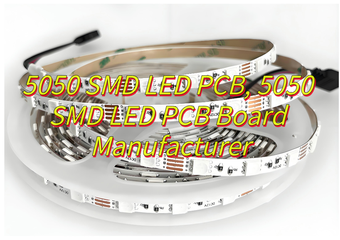
A 5050 SMD LED PCB refers to a printed circuit board specifically engineered to mount and operate 5.0mm × 5.0mm surface-mount device (SMD) LEDs, which feature multi-chip configurations for higher luminous flux or RGB color mixing. These PCBs manage electrical connectivity, heat dissipation, and mechanical stability, often utilizing aluminum-core substrates for high-power applications like stage lighting or UV curing. Unlike 3535 SMD LED PCBs (3.5mm × 3.5mm), which prioritize compactness for automotive interior lighting or instrumentation, or 2835 SMD LED PCBs (2.8mm × 3.5mm) optimized for slim-profile backlighting due to their lower height, the 5050 variant delivers superior brightness (up to 18 lumens per chip) and supports dynamic RGB effects. Compared to 5630 SMD LED PCBs (5.6mm × 3.0mm), which focus on energy efficiency for linear fixtures, 5050 PCBs emphasize versatility in color control and environmental resilience, making them ideal for decorative strips, commercial signage, and automotive accent lighting. Their design often incorporates multi-channel traces for PWM dimming and integrates thermal pads to mitigate heat accumulation in prolonged use.
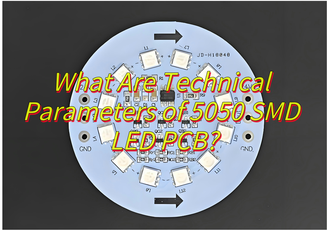
What Are Technical Parameters of 5050 SMD LED PCB?
Technical Parameters of 5050 SMD LED PCB:
Electrical Specifications
- Operating Voltage: 3.0–3.6V per LED chip, with transient voltage tolerance limited to ≤5V.
- Forward Current: 43–60mA per chip for full-intensity operation; reduced currents (14–20mA) lower brightness proportionally.
- Power Consumption: Ranges from 0.12W (low current) to 0.18W (high current) per LED.
Physical Dimensions
- LED Package: Standard size of 5.0mm × 5.0mm × 1.3mm (monochromatic) or 5.0mm × 5.0mm × 1.6mm (RGB).
- PCB/Strip Dimensions: Flexible strips commonly feature 10mm width and 2.4mm thickness, with configurable lengths.
Optical Performance
- Brightness: 5500–6000MCD per white LED chip.
- Luminous Flux: 18–21 lumens per chip, scalable based on LED density (e.g., 60 LEDs/m yields ~1080LM/m).
- Beam Angle: 120° viewing angle for standard variants; RGB versions achieve 115° semi-power beam angles.
- Color Options: Monochromatic (red, green, blue, white at 3000K–6000K) and programmable RGB combinations.
Thermal Management
- Operating Temperature Range: -20°C to +60°C ambient, with LED junction temperatures maintained ≤60°C.
- Cooling Solutions: Aluminum-core PCBs (MCPCB) or integrated thermal pads for heat dissipation in high-power setups.
Environmental Durability
- Waterproof Ratings: Options include IP65 (silicone-coated), IP67 (epoxy encapsulation), and IP68 (fully sealed) for outdoor or damp environments.
- Lifespan: 50,000–100,000 hours under stable thermal and electrical conditions.
Control & Compatibility
- Dimming: Supports PWM dimming for brightness adjustment.
- Dynamic Effects: Addressable RGB control via serial protocols (e.g., single-wire data transmission) for synchronized color transitions.
- Voltage Compatibility: Works with 5V, 12V, or 24V DC systems, depending on PCB design.
Mechanical & Material Properties
- Substrate Materials: FR4, aluminum, or flexible polyimide (for bendable strips).
- Mounting: Compatible with automated SMT assembly or manual soldering (max 250°C iron temperature).
What Are Application of 5050 SMD LED PCB?
Applications of 5050 SMD LED PCB:
Decorative and Architectural Lighting
- Used in flexible LED strips for ambient lighting in homes, hotels, and public spaces, enabling dynamic color transitions and patterns.
- Integrated into cove lighting, signage backlighting, and accent lighting for architectural highlights due to high brightness and RGB color mixing capabilities.
Commercial Displays and Advertising
- Featured in LED billboards, retail signage, and digital displays for vibrant visuals and uniform illumination.
- Supports large-scale video walls and interactive kiosks using addressable RGB control for synchronized content.
Entertainment and Stage Lighting
- Deployed in stage setups, concert lighting, and DJ equipment to create immersive color effects and dynamic scenes.
- Utilized in theatrical lighting systems for precise beam angles (115°–120°) and smooth color transitions.
Smart Lighting Systems
- Integrated into IoT-enabled smart home systems, allowing app-based control of brightness, color temperature, and RGB animations.
- Compatible with protocols like DMX or SPI for synchronized lighting in automated environments.
Specialized Industrial Applications
- Embedded in UV curing systems for printing or coating processes, leveraging high-intensity output for rapid polymerization.
- Applied in horticultural lighting for customizable spectra to support plant growth cycles.
Consumer Electronics
- Used in gaming peripherals, PC components, and wearable devices for customizable RGB backlighting.
- Incorporated into home appliances, such as smart speakers or TVs, for status indicators or aesthetic enhancements.
Automotive Accent Lighting
- Installed in vehicle interiors (footwells, dashboards) and exteriors for decorative lighting, complying with low-voltage DC systems.

How to Design High Power 5050 LED PCB to Avoid Overheating Issues?
Optimize PCB Material Selection
- Use metal-core PCBs (MCPCBs) with aluminum or copper substrates instead of standard FR-4. These materials offer superior thermal conductivity (e.g., 1.0–2.0 W/m·K for aluminum vs. 0.3 W/m·K for FR-4), enabling efficient heat dissipation from LEDs to the underlying metal layer.
- For extreme heat loads, consider ceramic-filled PCBs or thick copper layers (e.g., 3–4 oz/ft²) to enhance thermal transfer.
Strategic Component Placement
- Arrange 5050 LEDs with adequate spacing to prevent heat accumulation. A minimum gap of 2–3 mm between adjacent LEDs reduces thermal coupling.
- Avoid clustering high-power components (e.g., drivers, resistors) near LEDs. Isolate heat-generating parts using thermal barriers or dedicated thermal relief pads.
Enhance Thermal Vias and Copper Layers
- Incorporate arrays of thermal vias (0.3–0.5 mm diameter, spaced 1–2 mm apart) beneath each LED pad. These vias transfer heat from the top layer to internal or bottom copper planes.
- Dedicate a continuous ground plane on the PCB’s inner layers to act as a heat spreader. Connect it to the metal core via multiple thermal vias.
Maximize Copper Trace Width and Thickness
- Use 2–3 oz/ft² copper thickness for power traces to minimize resistive losses. Wider traces (e.g., 15–20 mil for high-current paths) reduce voltage drop and Joule heating.
- Avoid sharp bends in power traces to prevent current crowding and localized heating.
Incorporate External Heat Sinks
- Attach aluminum or copper heat sinks to the PCB’s metal core using thermal tape or screws. Ensure direct contact between the heat sink and LED thermal pads.
- For multi-layer PCBs, use exposed metal pads on the bottom layer to interface with external cooling systems (e.g., chassis mounting).
Improve Airflow Management
- Design the PCB layout to align with natural convection currents. Place LEDs perpendicular to airflow direction to maximize cooling efficiency.
- Add cutouts or slots in the PCB near heat-sensitive components to reduce airflow obstruction.
Implement Thermal Interface Materials (TIMs)
- Apply high-performance TIMs (e.g., silicone-based pads or phase-change materials) between LEDs and the PCB to minimize thermal resistance.
- Avoid excessive TIM thickness; 0.1–0.2 mm is typically sufficient for 5050 LEDs.
Thermal Simulation and Testing
- Use thermal simulation tools to model heat flow and identify hotspots before prototyping.
- Validate designs with infrared thermography during testing. Ensure junction temperatures stay below 85°C for reliable 5050 LED operation.
Power Management Considerations
- Use constant-current LED drivers with high efficiency (>90%) to minimize wasted power. Place drivers away from LEDs to prevent mutual heating.
- Implement PWM dimming instead of analog dimming to reduce average power dissipation.
Environmental and Mechanical Protections
- Coat PCBs with conformal coatings (e.g., silicone or acrylic) if exposed to moisture or dust, ensuring they do not insulate heat-dissipating surfaces.
- Avoid enclosing the PCB in airtight enclosures; leave ventilation gaps or use forced-air cooling for enclosed designs.
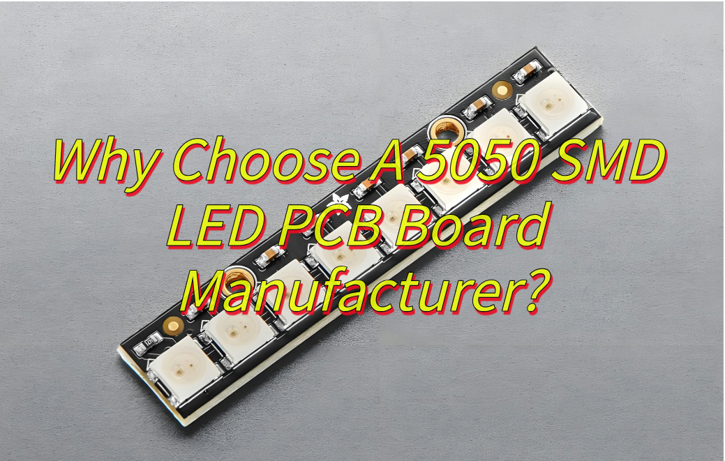
Why Choose A 5050 SMD LED PCB Board Manufacturer?
Below are how to choose a 5050 SMD LED PCB board manufacturer:
- Technical Proficiency: A reputable manufacturer demonstrates deep understanding of 5050 SMD LED technology, including thermal management, current regulation, and light uniformity. Their engineering team should optimize PCB layouts to minimize heat buildup and maximize energy efficiency, critical for longevity and consistent output.
- Material Quality: The choice of substrates, copper thickness, and solder masks directly impacts durability. Look for producers using high-grade FR-4 or metal-core materials to enhance heat dissipation and withstand environmental stressors like moisture or temperature fluctuations.
- Precision Manufacturing: Advanced equipment ensures tight tolerances in component placement and soldering. Automated assembly lines reduce human error, while optical inspection systems verify alignment and solder joint integrity, critical for avoiding failures in dense LED arrays.
- Customization Flexibility: Applications vary from automotive lighting to commercial signage. A versatile manufacturer accommodates custom PCB shapes, color temperatures, and driver configurations. They should also offer prototyping services to refine designs before mass production.
- Quality Assurance Protocols: Rigorous testing phases—including electrical continuity checks, aging tests, and photometric evaluations—guarantee compliance with industry standards like LM-80 for LED longevity. Certifications such as ISO 9001 or RoHS compliance further validate their commitment to quality.
- Scalability and Capacity: Whether for small batches or large-scale rollouts, the manufacturer’s production capacity and supply chain resilience matter. Assess their ability to handle peak demands without compromising lead times or quality.
- Cost-Efficiency: Competitive pricing should not come at the expense of quality. A balanced manufacturer optimizes material sourcing and production workflows to offer cost-effective solutions without cutting corners on critical specifications.
- Post-Production Support: Responsive technical support and warranty policies address issues promptly. Manufacturers offering lifecycle management, including recycling or upgrade paths, demonstrate long-term partnership potential.
- Industry Experience: Proven expertise across diverse sectors—from consumer electronics to industrial systems—indicates adaptability and problem-solving capabilities. Case studies or client testimonials can highlight their track record in delivering tailored solutions.
- Sustainability Practices: Eco-friendly processes, such as lead-free soldering and energy-efficient production lines, align with global sustainability goals. Inquire about their waste management and carbon footprint reduction initiatives.
How to Test Quality of 5050 SMD LED PCB Board?
How to Test Quality of 5050 SMD LED PCB Board:
Visual Inspection
- Method: Use a magnifying glass or microscope to examine solder joints, component placement, and PCB traces.
- Focus: Check for cold solder joints, misaligned LEDs, flux residues, or physical damages like scratches.
- Purpose: Identify manufacturing defects before electrical testing.
Electrical Continuity Testing
- Method: Apply a multimeter to verify connectivity between PCB traces, pads, and LED terminals.
- Focus: Ensure no open circuits or short circuits exist in critical pathways (e.g., power rails, data lines).
- Tools: Continuity tester or automated optical inspection (AOI) systems.
Forward Voltage and Current Testing
- Method: Use a programmable DC power supply to apply rated current (e.g., 60mA for 5050 LEDs) and measure voltage drop.
- Focus: Confirm voltage values align with datasheet specifications (typically 2.8–3.6V per color).
- Purpose: Validate LED functionality and detect early failures.
Reverse Leakage Current Test
- Method: Apply reverse bias voltage (e.g., 5V) and measure leakage current.
- Focus: Ensure leakage remains below 10µA to prevent premature degradation.
- Tools: Precision source measure unit (SMU) or LCR meter.
Thermal Performance Evaluation
- Method: Operate LEDs at maximum rated current for 4–8 hours while monitoring PCB temperature with thermal cameras or thermocouples.
- Focus: Check for hotspots near LEDs or power components. Ensure junction temperature stays below 120°C.
- Purpose: Assess heat dissipation efficiency and long-term reliability.
Color Consistency and Luminance Measurement
- Method: Use an integrating sphere or spectrometer to measure luminous flux, chromaticity coordinates, and color temperature.
- Focus: Compare results against binning standards to ensure uniformity across batches.
- Tools: Photometer or spectroradiometer.
Mechanical Stress Testing
- Method: Bend the PCB gently (within manufacturer-specified limits) and retest electrical continuity.
- Focus: Verify solder joint integrity under mechanical strain.
- Purpose: Simulate real-world handling or installation stresses.
Humidity and Corrosion Resistance
- Method: Expose the PCB to 85% relative humidity at 85°C for 96 hours (per IPC-TM-650 standards).
- Focus: Check for delamination, corrosion, or electrical drift post-exposure.
- Tools: Climate chamber.
Vibration and Shock Testing
- Method: Subject the PCB to sinusoidal vibration (5–2000Hz) and mechanical shock pulses (e.g., 50G, 11ms).
- Focus: Ensure no component displacement or trace fractures occur.
- Tools: Electrodynamic shaker or drop tester.
Aging and Lifecycle Testing
- Method: Operate LEDs continuously for 1000+ hours at elevated temperatures (e.g., 60°C) while monitoring luminous decay.
- Focus: Calculate L70/L90 lifespan metrics (time to 70%/90% initial brightness).
- Purpose: Predict long-term performance under accelerated conditions.
Electrostatic Discharge (ESD) Immunity
- Method: Apply ESD pulses (e.g., ±8kV contact discharge) per IEC 61000-4-2 standards.
- Focus: Verify LEDs and circuitry withstand static shocks without failure.
- Tools: ESD gun.
Documentation and Traceability
- Method: Record all test results, including serial numbers, batch codes, and environmental conditions.
- Focus: Create a audit trail for quality assurance and failure analysis.
- Tools: Laboratory information management system (LIMS) or spreadsheets.
How to Reduce Production Cost of 5050 SMD LED PCB Board?
To reduce the production cost of 5050 SMD LED PCB boards, consider the following structured approaches:
- Design Simplification: Streamline circuit layouts to minimize material usage and reduce etching complexity. Adopt standardized component placements to simplify assembly processes and lower labor demands.
- Material Selection: Choose cost-effective substrate materials, such as FR-4 with appropriate thickness, balancing performance and expense. Explore alternative solder mask colors or finishes that maintain functionality while reducing material costs.
- Component Sourcing: Partner with multiple suppliers to negotiate better pricing for 5050 SMD LEDs and passive components. Prioritize bulk purchases to leverage volume discounts without compromising quality.
- Process Optimization: Implement automated optical inspection (AOI) early in production to identify defects swiftly, minimizing rework and scrap. Optimize stencil design for solder paste printing to enhance consistency and reduce paste waste.
- Energy Efficiency: Upgrade manufacturing equipment to energy-efficient models, such as LED curing lamps or low-power reflow ovens, to cut utility expenses over time.
- Waste Reduction: Recycle scrap PCB material and unused components through certified vendors. Adjust panelization strategies to maximize board yield per panel, reducing edge trim losses.
- Labor Efficiency: Train staff on multi-skill development to handle multiple production stages, reducing dependency on specialized roles. Introduce lean manufacturing principles to eliminate non-value-added steps.
- Outsourcing Strategies: Collaborate with contract manufacturers for non-core processes like plating or specialized testing to leverage their economies of scale.
- Quality Management: Apply statistical process control (SPC) to monitor critical parameters, ensuring stable yields and avoiding costly batch failures.
- Long-Term Partnerships: Establish stable relationships with key suppliers for preferential pricing and priority access to advanced materials during shortages.
What Are Difference Between 5050 and 3535 SMD LED PCB Board?
The differences between 5050 and 3535 SMD LED PCB boards are as follows:
Physical Dimensions:
- 5050 LED: The package size is 5.0mm × 5.0mm × 1.6mm. The larger volume allows the integration of more components, such as built-in IC control circuits to form independent externally controlled pixels.
- 3535 LED: The package size is 3.5mm × 3.5mm × 0.5mm. It is smaller and suitable for high-density installation, but the internal space is limited and complex circuits are usually not integrated.
Power and Brightness:
- 5050 LEDs typically operate at 0.2W with a luminous intensity of 5500–6000MCD (pure white). Their design supports high brightness and wide illumination ranges, making them suitable for applications requiring substantial light output.
- 3535 LEDs are available in higher power ratings (up to 4W) and offer superior current handling. They deliver intense light output, with some variants achieving 320 lumens at 3W, ideal for high-intensity applications.
Thermal Performance:
- 5050 LEDs benefit from their larger footprint, which enhances heat dissipation. They maintain stability at operating temperatures between -35°C and 60°C, with transient tolerance up to 85°C.
- 3535 LEDs incorporate advanced thermal management, such as ceramic substrates and low thermal resistance (≤9°C/W), ensuring efficient heat transfer. They can operate at junction temperatures up to 95°C, making them robust for demanding environments.
Electrical Characteristics:
- 5050 LEDs typically run at 3.2–3.4V with a forward current of 60mA, aligning with standard LED parameters.
- 3535 LEDs support broader voltage ranges (e.g., 2.2–3.4V) and higher drive currents (up to 700mA), enabling flexible circuit design and compatibility with diverse power supplies.
Applications:
- 5050 LEDs are prevalent in indoor/outdoor decorative lighting, LED strips, automotive interiors, and backlighting for displays due to their balance of brightness and energy efficiency.
- 3535 LEDs excel in high-power applications such as road lighting, architectural illumination, medical devices, and automotive headlights. Their robustness and spectral tunability (e.g., 620nm red + 3000K warm white) suit specialized uses like horticultural lighting and entertainment systems.
Optical Design:
- Both models feature 120° viewing angles, but 3535 LEDs often include advanced optics like micro-prism diffusers to enhance light uniformity, critical for applications requiring precise beam control.
Durability and Lifespan:
- 5050 LEDs offer longevity up to 50,000 hours under standard conditions.
- 3535 LEDs match this durability while incorporating features like IP68 waterproofing and UV resistance, extending their utility into harsh environments.
Customization and Control:
- 3535 LEDs support advanced customization, including bin-based spectral sorting, programmable intensity/color temperature, and smart protocols (e.g., DMX512), catering to professional and industrial needs.
- 5050 LEDs focus on cost-effective solutions with basic color and brightness options, prioritizing ease of integration.
In conclusion, choose 5050 LED PCBs for cost-effective, versatile indoor solutions, and 3535 LED PCBs for high-power, durability-critical applications requiring precision and intensity.