





An LED’s solder-point or sensor-pad temperature is only useful for estimating junction temperature if it is measured at the location associated with the published thermal resistance. A nearby metal-base reading is not a substitute. Match the LED part, the reference location and the supplier’s power convention before calculating the junction estimate.
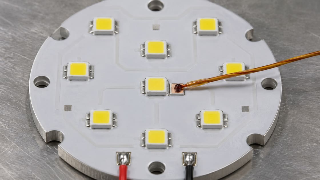
Identify the temperature reference on the drawing
Manufacturers may define a solder point, case reference, or dedicated sensor pad. Locate it in the application documentation for the exact package. Lumileds’ measurement white paper explains why the solder reference and case reference are not necessarily the same.
Record the parameters before powering the test
A measurement sheet should make the estimate repeatable.
| Parameter | Record | Example only |
| LED | Exact part and revision | Package-specific |
| Reference temperature | °C and sensor coordinates | 68 |
| Junction-to-reference resistance | °C/W, matching definition | 6 |
| Power | W on the specified basis | 2 |
| Assembly state | Sink, interface and airflow | Intended enclosure condition |
Estimate junction temperature from the example
For the illustrative compatible values, add the product of 6 °C/W and 2 W to 68 °C. The estimate is 80 °C. The example is not a component rating, and the power term must follow the manufacturer’s convention for the published resistance.
Compare solder point, metal base and ambient
These temperatures describe different parts of the assembly.
| Location | Useful for | Cannot replace |
| Specified solder or sensor point | Junction estimate with matching resistance | Direct junction measurement |
| Metal base or heat sink | Comparing assembly heat paths | Package-specific sensor reference |
| Ambient | Defining external operating condition | Board or package temperature |
Use the supplier’s power convention
Some manufacturer methods pair their published resistance with electrical input power. Others distinguish thermal power and emitted optical power. Do not independently subtract optical power or use electrical power by default; use the convention that accompanies the exact resistance value.
Place the sensor without changing the feature
Follow the supplier’s approved sensing location and attachment method. A bead on solder mask or an adjacent pad may not read the intended reference. Keep the sensor and leads from altering electrical clearance, thermal contact or the optical path.
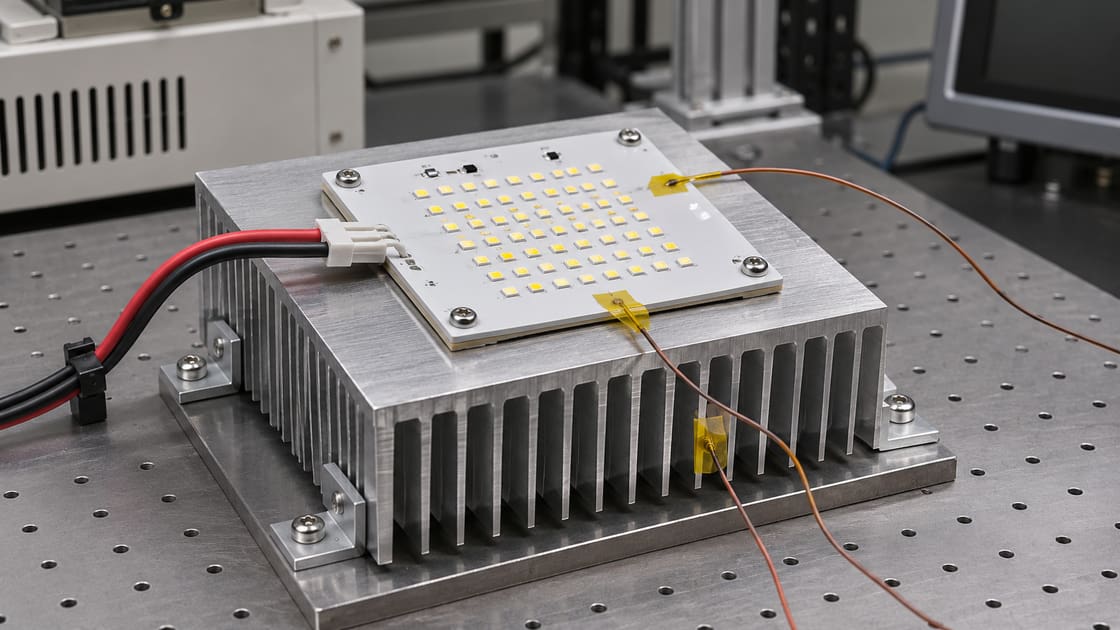
Check how the sensor affects the reading
Lead routing, attachment and sensor contact can influence the measurement. Document placement with a photo and check repeatability across equivalent samples. If the method requires a special test board or mounting procedure, reproduce that condition instead of improvising.
Measure in the relevant assembly state
Use the specified drive, airflow, mounting and interface condition. An LED on an open bench can run at a different temperature from the installed module. Record stabilization or the required timing so short transients are not mistaken for steady operation.
Keep board comparisons on the same reference
When comparing two MCPCBs, preserve the LED package, drive and sensor location. If the mount or heat sink also changes, the result compares two complete assemblies. Use the BestPCBs MCPCB stackup guide for the separate heat-path selection question.
Interpret uncertainty before claiming margin
A small apparent temperature advantage can be less than placement or measurement variation. Repeat the test and document the resistance tolerance or typical-value limitation. Avoid reporting an estimated junction temperature with more precision than its inputs support.
Know when the estimate does not apply
Do not use a steady-state resistance calculation to interpret an arbitrary short pulse. Follow the component documentation for transient operation. If the package reference or power basis cannot be matched, report the measured temperature and the unresolved limitation separately.
Hand off the evidence with the thermal review
Keep the LED part, reference drawing, sensor photo, drive power, stabilization record and mounting details together. Send the stackup and verification requirements to Best Technology at sales@bestpcbs.com for a manufacturing review.
FAQ
Can I measure the aluminum back and call it solder-point temperature?
No. The metal back is a different location, separated by part of the heat path. Use it to evaluate the assembly or compare mounts, but apply a junction-to-solder resistance only to its specified reference. Record both temperatures separately if both are useful.
Does an infrared image replace the thermocouple method?
Not automatically. Surface emissivity, reflections and spatial resolution can influence the camera result. Use the approved method for the defined point. An image can help locate gradients but cannot be assumed to reproduce a package-specific reference reading under all surface conditions.
Can I use a resistance value from another LED in the same footprint?
Do not assume it transfers. Package internals, thermal path and reference definitions can differ even with the same footprint. Use the correct part documentation and verify any supplier-approved alternative. A similar board land pattern does not establish the same temperature estimate.
Is the calculated result an exact junction measurement?
No. It is an estimate built from the reference temperature, resistance and power convention. Its accuracy depends on the applicability of the resistance and on how the measurement was taken. Keep uncertainty and any typical-value assumptions with the reported result for review.
Should I use the maximum junction rating as the design target?
An absolute limit is not automatically an operating target. Use the device and system requirements for the expected lifetime and conditions. Compare your estimate and its uncertainty with the approved design margin rather than aiming to operate exactly at the published maximum.
Can I take a reading immediately after switch-on?
Only if the test specifically calls for that transient condition and uses the corresponding method. A steady-state estimate needs a relevant stabilized reading. Record the drive duration and response so a cold-start value is not compared with a settled installed condition.
Does a colder metal base always mean a colder junction?
Not necessarily. The difference between the junction and the base depends on the package, board and interfaces. A cooler base is useful information but does not prove the junction changed by the same amount. Compare the specified reference under matched operating conditions.
What if I cannot access the specified pad?
Document the restriction and ask for an approved alternate method or a representative test coupon. Do not silently substitute a nearby surface and keep the original resistance value. A result with an unverified reference should be labeled as such rather than used for release.
You may also like

Tags: LED Thermal Design, MCPCB, Solder Point Temperature, Thermocouple