Two RF paths are phase-matched when their relative phase at defined reference planes stays within a specified limit over the relevant frequency band. Start by converting the phase limit to delay at each frequency, then include routing, launches and component tolerances. Equal drawn lengths alone do not guarantee equal phase.
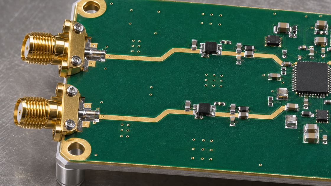
What phase matching means on a PCB
Phase is position within a signal cycle, expressed in degrees. For two paths carrying the same tone, compare their phases at the chosen output references after accounting for their inputs. The requirement can be equal phase or a defined offset.
What to put in the requirement
Specify the two paths, the measurement planes and the intended frequency band before setting a length tolerance.
| Field | Unit or definition | Example only |
| Test frequency | GHz | 6.0 |
| Allowed relative phase error | Degrees | ±3 |
| Target relative phase | Degrees | 0 |
| Effective permittivity | Dimensionless | 3.0 for an illustrative uniform line |
| Reference planes | Defined interfaces | Input and output launch boundaries |
| Test state | Condition and setup | Same temperature and matched ports |
Convert a phase limit to time
For a pure delay difference, phase magnitude in degrees is 360 times frequency in hertz times delay in seconds. At 6 GHz, 3 degrees corresponds to about 1.39 ps. This budget is for the total path difference at that frequency, not the portion reserved for PCB routing.
Estimate the corresponding routing mismatch
For an illustrative uniform line with effective permittivity 3.0, phase velocity is about 173 mm/ns. Multiplying by 0.00139 ns gives about 0.24 mm. Use that as a screening estimate only; different layers, dispersive structures or launches need a better model.
Physical length vs phase delay vs group delay
These quantities answer different questions.
| Quantity | What it describes | What can change it |
| Physical length | Drawn or manufactured conductor distance | Routing geometry |
| Phase at a tone | Relative angular shift at one frequency | Electrical length and discontinuities |
| Group delay | Negative slope of unwrapped phase with angular frequency | Frequency-dependent behavior across the band |
Why equal lengths can still differ
Different layers and reference geometries can change propagation. Different via transitions, launches or component footprints can add phase error even when the planar routes measure the same. Compare both complete signal paths, not only the longest straight traces.
What changes across a frequency band
Pure delay produces phase error proportional to frequency. Real paths may also show phase curvature because their behavior varies with frequency. A single point inside the limit does not establish a wideband match; sweep the full requirement and use consistent phase unwrapping.
How to allocate the total budget
Keep separate allowances for the PCB routing, launches, connector or component variation and measurement uncertainty. In a worst-case budget the signed contributions can add unfavorably. Use a statistical combination only if the assumptions and evidence support it.
What the reference planes should include
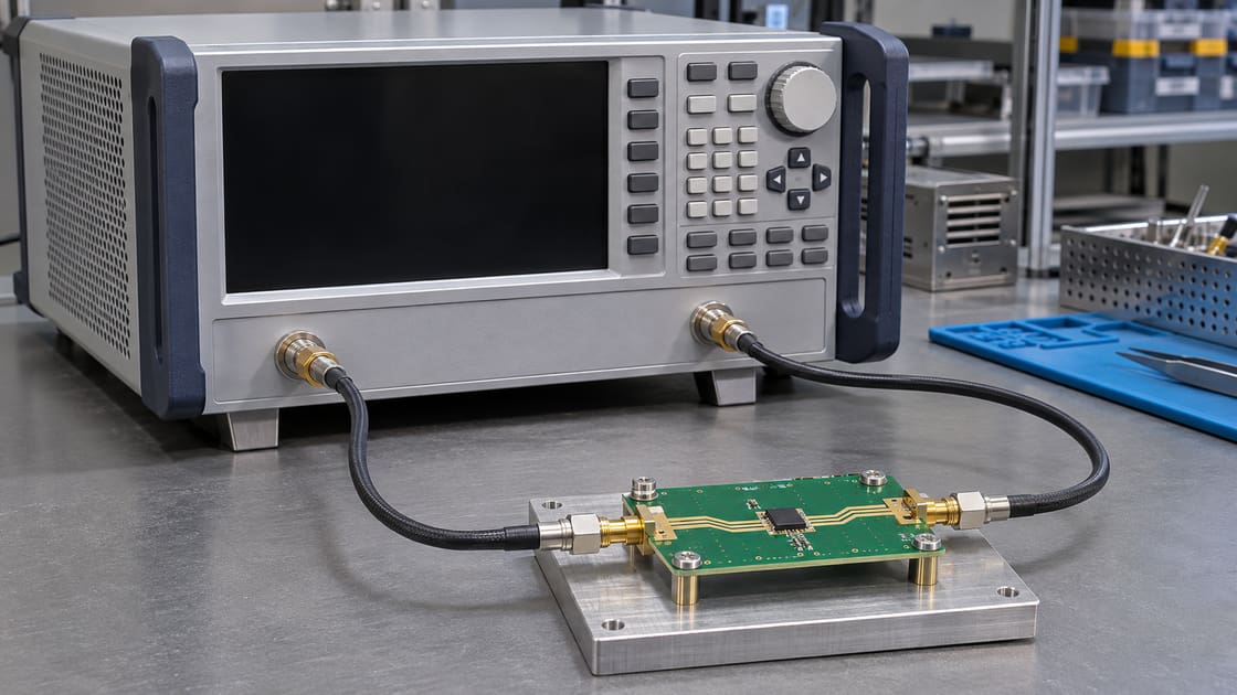
A system specification may include connector phase, while a board coupon test may remove the fixture. Choose the boundary before comparing results. Keysight’s guide to network analyzer delay functions distinguishes group delay, electrical delay and port extension; record which function was used so the results are reproducible.
How to measure a path pair
Measure each path under the same calibrated setup, with stable cables and corresponding port terminations. Compare unwrapped transmission phase across the band and report the difference with the target offset. Repeat connections where fixture repeatability could consume the allowance.
What to check before adding a meander
Verify which section causes the phase difference. Adding length may help a delay mismatch, but it will not necessarily correct a frequency-dependent launch issue. Tight tuning segments can change coupling, so validate the actual routed geometry rather than adding a generic serpentine.
What to release with the PCB files
Include the frequency band, phase target and allowable error, exact layer stack, reference-plane definitions and test conditions. For context see the PCB trace length matching guide. Send fabrication and coupon requirements to Best Technology at sales@bestpcbs.com.
FAQ
Is a ±3-degree limit always equal to ±1.39 ps?
No. That conversion applies to a pure delay error at 6 GHz. At other frequencies the same phase angle corresponds to a different delay. If the limit applies across a band, perform the conversion at the relevant frequencies and check the measured response.
Do two 50-ohm traces necessarily have the same phase?
No. Impedance and propagation delay are different characteristics. Two structures may have the same nominal impedance while using different dielectric geometries or materials. Compare electrical length and the complete path response rather than treating the impedance callout as a phase requirement.
Can I use the laminate’s bulk dielectric constant directly?
Not for every line structure. A surface trace can have fields in both substrate and surrounding media. Use an effective propagation value appropriate to the line geometry and band, or a validated field solution. Label any assumed value in the calculation.
What is phase wrapping?
An instrument can display phase within a fixed angular interval, making a continuous trace jump by 360 degrees at the boundary. Apply a consistent unwrapping and reference convention before interpreting delay or comparing trends. Retain the original data for review.
Does matching at center frequency prove broadband matching?
No. Two paths can cross at one frequency and differ on either side. Compare the full specified band and inspect phase slope or ripple when needed. In a broadband design, the useful evidence is the response under the actual test conditions.
Why do repeated measurements sometimes disagree?
Cable motion, connector torque, calibration drift and fixture repeatability can change phase. Repeat the measurement with stable setup conditions and record any reconnection. If measurement variation is comparable to the allowance, improve the setup before drawing a design conclusion or changing the routing.
Can unequal line lengths produce a desired phase offset?
Yes, over a defined design range, but verify the frequency dependence. A fixed additional delay does not generally produce a constant nonzero phase across a broad band. Define whether the specification is an angle at a tone or a delay or response across a band.
Should I put the entire phase allowance into trace length?
No. The complete paths can include launches, transitions and parts, and the verification itself has uncertainty. Allocate an explicit portion to routing, then check the complete path against the requirement. Reserve margin for manufacturing and test variability supported by evidence.
You may also like

Tags: Electrical Length, Phase Matching, RF PCB, VNA