





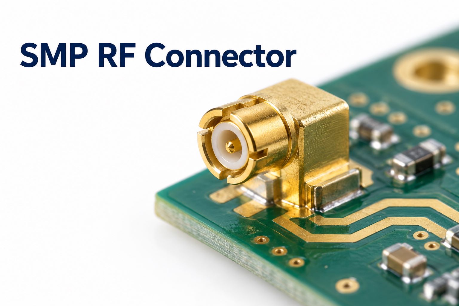
An SMP RF connector is a compact, 50 Ω coaxial connector with a push-on interface for board-to-board and cable-to-board connections. Selected designs support frequencies up to 40 GHz. Choosing one for a PCB requires matching its electrical rating, retention style, mounting geometry, and mating arrangement to the application.
At EBest Circuit, we support RF PCB fabrication and assembly, including Rogers and Rogers/FR4 hybrid boards. For an SMP-based project, the connector drawing, production stackup, and assembly requirements should be reviewed together before the board is released.
What Is an SMP RF Connector?
SMP stands for Subminiature Push-on. It identifies a miniature RF mating interface rather than one particular cable, PCB footprint, or mounting method.
Like other coaxial connectors, an SMP connector has a central signal contact surrounded by an outer conductor. The mating parts engage along the connector axis, using spring contacts to establish the electrical connection. Depending on the interface geometry, the connection provides either a distinct snap or a lower-retention sliding fit.
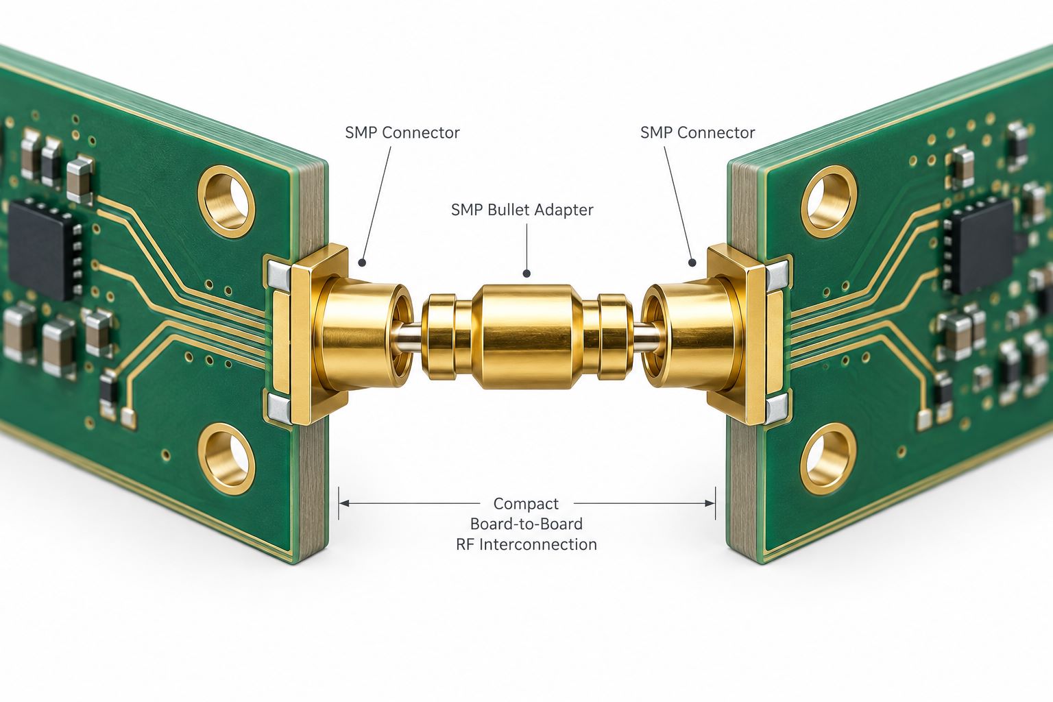
SMP connections appear in two main arrangements. A cable-to-board connection brings a coaxial cable directly onto a PCB. A board-to-board connection joins facing PCB connectors through an intermediate adapter, allowing an RF signal to move between stacked boards.
The connector name alone therefore leaves several purchasing details open. A complete specification identifies the manufacturer’s part number, mating contact arrangement, retention option, and PCB or cable termination. Check the interface drawing rather than selecting the mating half from a product photograph.
What Are the Key SMP RF Connector Specifications?
The main SMP specifications are impedance, operating frequency, reflection performance, insertion loss, power handling, and mechanical endurance. Use the selected part’s datasheet as the acceptance reference.
| Parameter | What to Verify |
|---|---|
| Nominal impedance | A 50 Ω interface matched to the system transmission path |
| Frequency range | The rating of the exact connector, adapter, or cable assembly |
| VSWR or return loss | Performance limits across the required operating band |
| Insertion loss | Maximum loss in dB, with frequency and measurement conditions |
| Power handling | Permitted power at the stated frequency and temperature |
| Mating endurance | Rated cycles for the selected detent and connector construction |
| Mechanical tolerance | Permitted axial movement, angular offset, and mating dimensions |
These specifications describe a particular product under stated conditions, rather than guaranteeing the performance of every SMP connection.
Frequency deserves particular attention. Samtec, for example, offers an SMP-TH2 through-hole series rated to 20 GHz and an SMP-TH series rated to 40 GHz. Both use the SMP interface.
When comparing electrical data, check what the measurement includes. Data from a connector mounted on a test PCB may include the connector-to-board transition as well as the connector itself.
How Do SMP Connector Detent Types Differ?
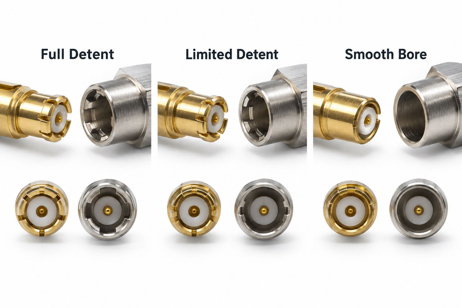
Full detent, limited detent, and smooth bore differ mainly in retention geometry and the force needed to separate the connection. Choose them according to how the assembly is held together and serviced.
| Interface | Retention Behavior | Practical Use |
|---|---|---|
| Full detent | Strong snap engagement | Connections that rely on the interface to remain mated |
| Limited detent | Reduced snap retention | Applications needing a balance between retention and removal effort |
| Smooth bore | Lower-retention sliding engagement | Floating connections or assemblies retained by other hardware |
A full-detent interface has an undercut that captures the mating spring contacts. Smooth bore omits that undercut, allowing easier separation. Limited detent provides an intermediate arrangement.
Retention strength and mating endurance are separate specifications. As an example, SV Microwave lists 100 cycles for full detent, 500 for limited detent, and 1,000 for smooth bore in its SMP interface summary.
Treat those figures as supplier-specific guidance. For a production fixture, review both the expected maintenance cycle count and the load that the connection must withstand.
Which SMP Connector PCB Mounting Options Are Available?
SMP PCB connectors are available in surface-mount, through-hole, mixed-technology, and edge-mount configurations. The choice determines where the connector sits and how its contacts attach to the board.
- Surface-mount versions attach to PCB lands and suit layouts that need a connector above the board surface. Check the approved soldering process and the space required by the mating half.
- Through-hole and mixed-technology versions use leads or mounting legs that enter the PCB. Mixed technology can combine a surface-mounted signal contact with through-board anchoring.
- Edge-mount versions position the connection at the board perimeter. The connector opening, signal-contact height, and PCB edge geometry must match the specified board construction.
Manufacturer options can be thickness-specific. Samtec’s SMP-MT series, for instance, includes versions for 1.60 mm and 2.36 mm boards.
Keep the mounting choice separate from the detent choice. First establish the physical attachment and mating direction; then specify the required retention option within the available product family.
How Do SMP Bullet Adapters Connect Two PCBs?
An SMP bullet adapter connects two facing PCB connectors through a short, typically female-to-female coaxial interconnect. The common arrangement is a male PCB connector on each board with the bullet between them.
The bullet provides a floating connection that accommodates specified axial and radial misalignment. Axial tolerance concerns separation along the mating direction. Radial alignment concerns the lateral offset and resulting angle between the mating parts.
A common retention arrangement uses full detent on the board that should retain the bullet and smooth bore on the opposite board, provided the bullet is suitably constrained. This helps make disassembly predictable.
Select the bullet together with both board connectors and the mechanical tolerance stack. Include connector heights, PCB positioning, mounting hardware, and expected board movement. Bullet overall length alone does not establish the finished board spacing.
Where additional controlled movement is needed, a spring-loaded bullet may be appropriate. Its working compression range and RF rating still need to cover the actual assembly dimensions. Board supports should establish the mechanical spacing rather than forcing the RF contacts to act as structural stops.
What Is the Difference Between SMP and SMA Connectors?
SMP uses a push-on connection, while SMA uses a threaded coupling. That difference changes the space needed for installation and the way the connection is secured.
| Consideration | SMP | SMA |
|---|---|---|
| Mating action | Axial push-on or snap-on | Threaded coupling nut |
| Installation access | Clearance along the mating axis | Access to engage and tighten the nut |
| Dense board stacks | Supports bullet-based blind mating | Usually connected through accessible cables |
| Retention | Detent or external retention arrangement | Properly tightened threaded coupling |
For a closely spaced board stack, SMP is often the more practical starting point. For an accessible cable port, SMA may fit the installation and service requirements more naturally. These are application choices rather than a universal performance ranking.
Frequency also remains part-specific. Compare the actual connector and assembly ratings rather than assuming that one interface always provides greater bandwidth.
The two can coexist in one product. An SMA-to-SMP cable assembly can connect an accessible SMA port to a compact SMP connection inside the equipment.
What Is the Difference Between SMP and SMPM Connectors?
SMPM is a smaller RF interface developed for higher connection density and higher-frequency applications than conventional SMP designs. Suppliers offer SMPM products rated up to 65 GHz, although the usable range still depends on the chosen connector and interconnect.
The main decision is whether the smaller interface solves a packaging or electrical requirement. In a multi-channel module, reduced connector size can help fit more RF connections into the available board area.
Both families support push-on connections, PCB mounting options, and bullet-based board-to-board arrangements. Their mating dimensions are different, so an SMPM connector requires the appropriate SMPM mating part rather than an SMP counterpart.
Changing from SMP to SMPM also means revisiting the connector footprint, board spacing, cable termination, and assembly access. It is a mechanical redesign as well as a component substitution.
For an existing SMP design that meets its frequency and density targets, retaining the established interface may be the simpler engineering choice. Select SMPM when its size or performance addresses a defined requirement.
Where Are SMP RF Connectors Used?
SMP RF connectors are used in compact radar modules, communication equipment, test systems, and other RF assemblies where removable connections must fit into limited space. Manufacturers offer both board-to-board and cable-to-board configurations for these applications.
Radar and communication modules: SMP interconnects can carry RF signals between adjacent circuit assemblies. A bullet connection suits a parallel board stack, while a cable assembly allows more freedom in the relative positions of the boards.
Wireless infrastructure: A small coaxial connection can link an RF module to another board or an internal cable harness. The relevant questions are the available height, signal frequency, and access during module replacement.
Test and measurement equipment: SMP connections support compact fixtures and modular RF paths. A test fixture also calls for attention to repeated mating and convenient replacement of wear items.
Consider where the connection sits within the equipment, not just the industry name. An internal board stack and an externally accessible test port can need different retention, sealing, and service arrangements even in the same product.
How Do You Choose an SMP RF Connector for Your PCB?
Choose an SMP RF connector by narrowing the electrical requirements first, then checking the complete mechanical and assembly arrangement. A useful review sequence is:
- Define the RF requirement. Specify operating band, allowable insertion loss, reflection limit, and power conditions. Include the complete cable or bullet path in the requirement.
- Choose the connection architecture. Decide whether the project needs cable-to-board routing, a parallel board stack, or another arrangement. Establish the mating direction and service access.
- Match the mounting and retention options. Select the PCB attachment style, then decide which interface or external hardware will retain the connection.
- Check the dimensional stack. Compare finished board thickness, connector height, board spacing, bullet working range, and allowable misalignment against the mechanical drawing.
- Release a complete part definition. Record both mating part numbers, the bullet or cable assembly, approved footprint, and assembly instructions in the project documentation.
This brings the supplier’s electrical specifications and PCB attachment requirements into the same review.
As an illustrative case, a low-profile receiver with two parallel PCBs might start with surface-mount connectors and a bullet. An enclosure that places the boards at different angles may be better served by a cable assembly.
Before purchasing, request the supplier’s drawing and electrical data for the exact configuration being quoted.
How Should You Design an SMP Connector PCB Footprint?
Build the SMP connector footprint from the exact part’s recommended PCB layout and mechanical drawing. The mating interface may be standardized, but the board attachment is specific to the connector construction.
Review three groups of details:
- Solder attachment: Confirm the center-contact land, ground-contact lands, solder-mask openings, and stencil requirements for the intended assembly process.
- Mechanical fit: Check mounting-hole size and plating status, connector seating position, PCB edge location, and permitted finished board thickness.
- Assembly clearance: Include the connector body, mating connector or bullet, insertion travel, and access for any handling tool in the mechanical review.
Keep the drawing revision associated with the library part. A similar outline or matching interface name is not sufficient evidence that two connectors share the same land pattern.
Also ask which stackup the supplier’s recommended layout assumes. A dimensional footprint establishes physical fit; electrical optimization may require additional ground clearances, vias, or transition features. Preserve the critical attachment dimensions while working with the supplier on RF-related changes.
How Does PCB Layout Affect SMP Connector RF Performance?
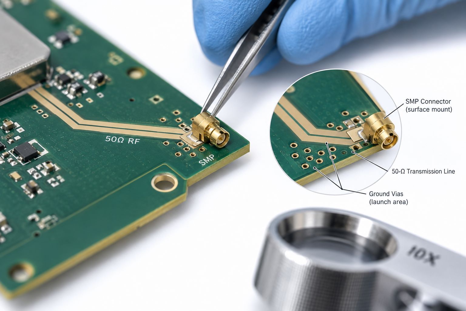
PCB layout controls how the RF signal transfers from the SMP connector into the board’s transmission line. This transition, usually called the RF launch, includes more than the visible solder pads.
The center-contact pad, surrounding grounds, dielectric thickness, and any signal via form one electrical structure. A nominally 50 Ω trace can still have a poorly matched connection at its entrance.
Give the return current a deliberate route from the connector body into the PCB ground system. Nearby ground vias and appropriate reference planes help shape that route. Intentional local plane clearances may also be part of an optimized launch, so blanket copper-filling rules are unsuitable here.
For demanding bandwidth or reflection targets, model the connector and transition using the production stackup. Include the relevant pad, via, ground, and dielectric geometry rather than simulating the trace alone.
Then verify prototype performance across the operating band. Return-loss and insertion-loss measurements should use defined reference planes, with fixture effects accounted for when required. This makes the measured result meaningful for the interconnect being evaluated.
How Are SMP Connectors Assembled onto RF PCBs?
SMP connectors are assembled using the soldering or mechanical attachment process approved for the selected part. Position, seating height, and ground attachment all need to remain consistent with the connector drawing.
For soldered versions, confirm the permitted thermal exposure before choosing the reflow or localized soldering process. The connector’s dielectric construction affects its behavior during heating; suppliers offer reflow-stable versions for applications where dimensional stability is important.
Control the solder deposit and hold the connector in its intended position. After soldering, inspect the center-contact joint, ground attachment, seating, and any visible tilt. A connector that has shifted can create both mating and RF-transition problems.
Gold-plated solderable surfaces deserve a specific review. Where the assembly specification requires gold removal, supplier-prepared pre-tinned versions can simplify the process. Follow the applicable part and assembly requirements rather than applying the same treatment to every connector.
For solderless versions, use the specified fastening procedure and board geometry. Final verification should cover mechanical fit, electrical continuity, and any project-defined RF measurements. Visual inspection and an RF performance test answer different questions.
FAQs About SMP RF Connectors
1. Are SMP and GPO connectors the same?
GPO is a trade name associated with the SMP mating interface. Rosenberger explicitly lists its SMP connectors as mateable with GPO connectors. For substitution, still verify the detent, mechanical drawing, and electrical specifications of the selected parts.
2. Can an SMP connector connect to an SMA cable?
Yes, through a suitable SMP-to-SMA adapter or cable assembly. Specify the required mating interface at each end and verify the frequency rating of the complete assembly, including the cable.
3. Do SMP connectors require a special tool?
Push-on mating does not require tightening a coupling nut. However, a purpose-made insertion and extraction tool can improve access and handling for small bullet adapters, especially in closely spaced assemblies. Follow the connector supplier’s handling procedure.
4. Are SMP connectors waterproof?
Waterproofing requires a specifically rated design and mating arrangement. For example, Amphenol’s IP67 SMP solutions require a matched pair; mixing an IP67 part with a standard mating part does not preserve that rating.
5. Can SMP connectors be used on FR4 PCBs?
Yes, provided the complete RF path meets the project’s loss, impedance, and frequency requirements. Evaluate the actual FR4 construction and trace length. A low-loss RF laminate becomes appropriate when the electrical requirements call for it.
EBest Circuit supports RF PCB fabrication and assembly, including controlled-impedance boards and Rogers/FR4 hybrid constructions. Our manufacturing support covers the board and assembly around the selected connector.
For your next SMP-based RF PCB project, send your Gerber or ODB++ files, BOM, stackup, connector part numbers, operating frequency, and required quantity to sales@bestpcbs.com. Include any mating-height, inspection, and RF test requirements so the fabrication and assembly quotation reflects the complete build.
You may also like



Tags: SMP bullet adapter, SMP connector PCB footprint, SMP RF connector