





To differentiate between direct current and alternating current, determine whether the current keeps flowing in one direction or reverses direction over time. Direct current (DC) is unidirectional and normally keeps fixed polarity. Alternating current (AC) reverses direction periodically, so its polarity alternates.
Direction is the deciding property, while source markings, waveform shape, frequency and meter readings provide supporting evidence. This distinction matters because a changing voltage is not automatically AC, and a DC supply does not have to produce a perfectly flat line.
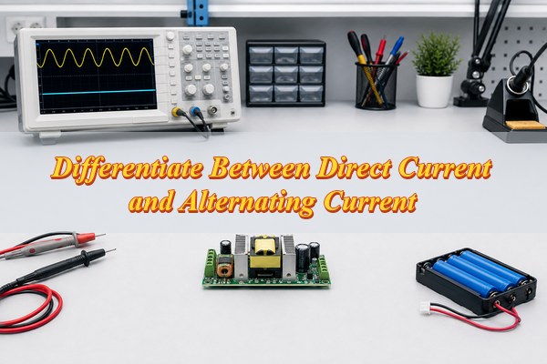
How Can You Differentiate Between Direct Current and Alternating Current?
Start with current direction, then confirm the result from polarity, waveform, source markings and an appropriate measurement. This provides a reliable way to differentiate between direct current and alternating current. Work at a named pair of terminals or test points because the input and output of the same device may use different current types.
- Define the measurement point: Identify the two terminals and the expected voltage range. This prevents an AC input and a DC output from being treated as one source.
- Check direction and polarity: Current that stays unidirectional, with the same terminal remaining positive relative to the other, is DC. Periodic reversal of direction and polarity identifies AC.
- Read the waveform: A trace that repeatedly crosses its reference in both directions is AC. A varying trace that remains on one side is DC or pulsating DC, even when it has a repeating shape.
- Read the source markings: Look for V⎓, V~, a polarity diagram and separate input and output ratings. Treat the voltage number as magnitude information, not as proof of AC or DC.
- Confirm with a suitable measurement: Compare DC-voltage and AC-voltage readings using equipment rated for the circuit. A result in both modes can indicate DC with ripple or an AC waveform with a DC offset, so interpret both readings at the same test point.
A “12 V” marking alone does not answer the question. It could describe a battery, a 12 V DC adapter output or a 12 V AC transformer secondary. The unit gives the voltage level; the symbol and polarity information identify the current type.
Why Are Direction and Polarity the Defining Differences Between AC and DC?
AC and DC are classified by how charge flow behaves over time. In a DC circuit, conventional current continues through the circuit in one direction. In an AC circuit, the driving voltage reverses polarity, causing conventional current in a resistive load to reverse as well.
Polarity provides a practical way to observe that direction. A DC source normally keeps the same terminal positive relative to the other terminal. An AC source makes each terminal alternate between positive and negative relative to the other. The voltage magnitude may change in either system, so magnitude alone does not define AC or DC.
| Characteristic | Direct current (DC) | Alternating current (AC) |
|---|---|---|
| Direction | Charge flow remains unidirectional, although its magnitude may rise or fall | Charge flow reverses direction at repeating intervals |
| Polarity | The same terminal normally remains positive relative to the reference | Each terminal alternates between positive and negative relative to the other |
| Voltage over time | May be steady, slowly changing or pulsating without crossing the reference | Changes sign relative to the reference as polarity reverses |
| Typical waveform | Flat level, sloping level or one-sided pulses; ripple may ride on the DC level | Sine, square, triangular or distorted waveform that alternates between polarities |
| Frequency | Steady DC is 0 Hz; ripple or switching noise can add periodic components | Has an alternating frequency, such as 50 or 60 Hz for utility power |
| Typical notation | V⎓, DC, or a solid line above a dashed line; polarity may be marked + and − | V~, AC, a tilde or a sine-wave symbol; frequency may also be stated |
| Practical confirmation | DC mode shows the main level and polarity; reversing the probes reverses the sign | AC mode shows the alternating component; an oscilloscope confirms repeated polarity reversal |
Frequency supports the classification but does not replace the direction test. Ripple on a DC rail has a frequency, yet the rail remains DC if its overall polarity does not reverse. This is why direction and polarity come before frequency when the result is uncertain.
What Do AC and DC Waveforms Look Like?
A DC waveform remains on one side of the zero reference, whereas an AC waveform alternates across the reference. A flat DC line and a sine-wave AC trace are familiar examples, but waveform shape by itself is not the definition.
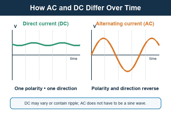
- Steady DC: The trace appears as a flat horizontal level because magnitude and polarity remain constant. A battery that slowly falls in voltage during discharge is still DC because its direction does not reverse.
- Pulsating DC: The trace repeatedly rises and falls while remaining on one side of the reference. An unfiltered rectifier output is a common example: it varies with time but remains unidirectional.
- Sine-wave AC: The trace moves smoothly above and below the reference, so its polarity and current direction reverse during every cycle.
- Nonsinusoidal AC: Square, triangular and distorted traces change shape differently, but they are still AC when they repeatedly alternate between positive and negative polarity.
On a real measurement, the zero reference must be defined correctly. A waveform may appear to sit above zero because it carries a DC offset even though an AC component is present. That mixed case is addressed separately below.
How Can You Tell Whether a Voltage Is AC or DC With a Multimeter?
Identify the test point and expected range, then measure the same two points in DC-voltage and AC-voltage modes. DC mode reports the average level and polarity; AC mode reports the alternating component within the meter’s bandwidth. Comparing the two prevents ripple or DC offset from being mistaken for a single current type.
- Identify the circuit and test point: Read the source label, choose the exact terminal pair and estimate the maximum voltage. The input and output of a charger, inverter or power supply may require different settings.
- Verify the meter setup: Confirm that the meter, probes and measurement category are rated for the circuit, and place the leads in the correct sockets. Start on a higher range if the value is uncertain. Do not probe live mains unless you are qualified and equipped to do so.
- Measure in DC-voltage mode: Select V⎓ and connect the probes across the test points. A stable positive value shows the red probe is at the more positive point; a stable negative value usually means the probes are reversed. A value that changes but keeps the same sign can still be DC.
- Measure the same points in AC-voltage mode: Select V~ without moving the test points. A substantial reading indicates an alternating component, but the displayed value depends on the meter’s bandwidth, waveform response and AC-coupling method.
- Compare the two results: A battery should show its main value in DC mode and little AC apart from noise or ripple. A transformer secondary should show its main value in AC mode. A regulated DC supply with measurable AC usually contains ripple rather than having changed into an AC source.
- Resolve an ambiguous result: If both readings are significant, check the circuit documentation and observe the waveform with a properly rated oscilloscope. Confirm whether the signal crosses the reference, carries a DC offset or contains switching pulses before assigning the final classification.
A nonzero reading in both modes does not automatically mean the meter is wrong. It may indicate DC with ripple, an AC signal with DC offset, electrical noise or a measurement limitation. Interpret the reading at the exact test point rather than assigning one current type to the entire device.
Which Common Power Sources Provide AC and Which Provide DC?
Batteries, USB ports and photovoltaic panels normally provide DC, while wall outlets, alternators and conventional transformer secondaries normally provide AC. Conversion equipment can make the input and output different, so always identify the side of the device being discussed.
- Batteries and cells: These provide DC with defined positive and negative terminals. Their voltage can fall with discharge and load without changing the classification.
- USB and regulated electronic outputs: These provide DC at a specified nominal voltage. Switching ripple may be present on the output.
- Photovoltaic panels: Individual panels generate DC. A solar inverter converts that DC into AC for conventional AC loads or grid connection.
- Household wall outlets: These provide AC at the local utility voltage and frequency. Appliances often convert it to DC internally.
- Generators and alternators: Their electrical output is commonly AC. A rectifier may be added when the connected system requires DC.
- Transformer secondaries: A conventional transformer changes an AC voltage level but still produces AC. A complete wall adapter adds rectification and regulation to provide DC.
The source category is a useful clue, not a substitute for reading the terminals. An inverter receives DC but delivers AC. A phone charger receives AC at its wall input and delivers DC at its USB output.
Can AC and DC Exist in the Same Circuit at the Same Time?
Yes. One device can contain separate AC and DC sections, and one conductor can carry a DC level with an AC component superimposed on it. The correct description depends on the test point and the purpose of the measurement.
A nominal 5 V DC rail may carry 50 mV peak-to-peak switching ripple. The 5 V average level is the DC component, while the repeating variation is the AC component. The rail is still called a DC supply because its polarity remains fixed and the DC level supplies the load.
Biased audio and sensor circuits provide another example. The signal may swing above and below a DC bias voltage without crossing the circuit’s zero reference. AC coupling can remove the DC component for analysis, while DC coupling shows the combined waveform.
A power adapter contains both forms at different locations: AC at the input, pulsating DC after rectification and smoother DC after filtering and regulation. Identifying the current type therefore requires a test-point reference, not a label applied to the whole product.
How Is AC Converted to DC and DC Converted to AC?
A rectifier converts AC to DC, and an inverter converts DC to AC. Filtering and regulation are normally added when the next circuit needs a controlled voltage rather than the raw converted waveform.
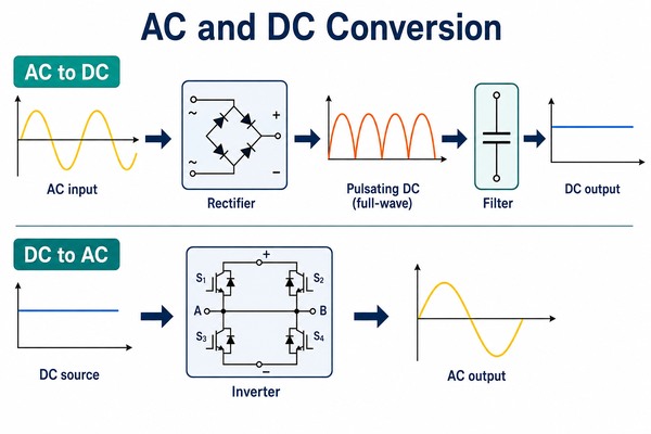
- Rectifier, AC → DC: Diodes or controlled switches make the output unidirectional. A reservoir capacitor reduces the variation, and a regulator can hold the output closer to its target.
- Inverter, DC → AC: Power switches reverse the output polarity in a controlled sequence. The switching pattern and filtering determine the resulting AC waveform.
- DC-DC converter, DC → DC: A switching stage raises, lowers or isolates a DC voltage to create another DC rail. Internal switching does not make the final output AC when its polarity remains fixed.
A typical mains-powered electronic device follows the path AC input → rectifier → DC bus → regulated DC outputs. A battery-powered inverter follows the opposite direction when it must operate an AC load. The labels at each stage should state which voltage is being measured.
What Common Mistakes Cause AC and DC to Be Misidentified?
Most errors come from relying on one visual clue instead of checking direction, polarity and the exact measurement point. Each mistake below includes the check that corrects it and helps prevent it from recurring.
- Mistake — “DC must be perfectly flat”: DC can change in magnitude or contain ripple while remaining unidirectional. Prevention: Check whether the waveform reverses polarity; if it stays on one side of the reference, classify the main component as DC.
- Mistake — “AC must be a sine wave”: Square, triangular and distorted waveforms are also AC when they alternate between polarities. Prevention: Judge the repeated direction reversal rather than the curve shape.
- Mistake — “A voltage number identifies the type”: A 12 V rating can describe AC or DC. Prevention: Read the adjacent V⎓ or V~ symbol, polarity diagram and separate input/output label before connecting a load.
- Mistake — “The entire device uses one current type”: Chargers, power supplies, inverters and drives can contain AC and DC at different stages. Prevention: Name the exact terminals or test point in the schematic, procedure and measurement record.
- Mistake — “One meter mode tells the whole story”: DC mode can hide ripple, while AC mode can omit the average DC level. Prevention: Compare both modes at the same points and use an oscilloscope when the waveform matters.
- Mistake — “Any repeating waveform is AC”: Pulsating DC repeats but does not reverse polarity. Prevention: Use direction as the deciding test and frequency only as supporting evidence.
FAQs About Direct Current and Alternating Current
Q1: Is DC always positive?
A1: No. DC can be positive or negative relative to the chosen reference. It is classified as DC because its direction remains fixed, not because its voltage must be above zero.
Q2: Is 120 V AC equivalent to 120 V DC?
A2: No. The ratings cannot be treated as interchangeable. Utility AC is normally stated as an RMS value, and its peak voltage is higher than the RMS number. Component stress and safety depend on the complete circuit conditions.
Q3: Can a conventional transformer operate from DC?
A3: A conventional transformer requires changing current to sustain transformer action. Steady DC does not provide that continuous change and can overheat a winding if applied improperly.
Q4: Why does a multimeter show an AC reading on a DC supply?
A4: The supply may contain ripple, switching noise or coupled interference. The value also depends on the meter’s bandwidth and AC measurement method, so an oscilloscope may be needed to characterize it.
Q5: Is conventional current direction the same as electron movement?
A5: Conventional current is defined in the direction positive charge would move, opposite to electron drift in a metal conductor. AC and DC classifications normally use conventional current direction.
Q6: Is AC more dangerous than DC?
A6: Neither should be assumed safe. Risk depends on voltage, available current, contact duration, current path, frequency and circuit conditions. Use equipment and procedures rated for the actual source.
Conclusion
The reliable way to distinguish AC from DC is to determine whether current direction and voltage polarity reverse over time. Waveform shape, frequency, source markings and multimeter readings confirm that result. This same test also separates AC from pulsating DC and explains how a DC rail can carry a smaller AC ripple component.
When a product converts or distributes AC and DC, document the voltage type and expected level at each test point. For PCB fabrication or assembly support on a power-conversion design, send the board files, BOM and test requirements to sales@bestpcbs.com.
You may also like







Tags: Alternating Current, Current Direction, Current Measurement, Direct Current