





Learning how to discharge a capacitor safely means removing stored energy through a controlled resistance and then verifying the remaining voltage with a correctly rated meter. Disconnect every energy source first. Do not bridge the terminals with a screwdriver or bare wire; the resulting current can create an arc, damage the capacitor or PCB, and injure the operator.
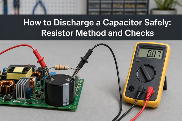
Safety boundary: The procedure below is for trained people working on isolated electronic circuits whose voltage, capacitance, stored energy, and service instructions are known. Do not open or service microwave ovens, HVAC equipment, mains power supplies, photoflash units, EV inverters, medical equipment, industrial drives, or capacitor banks without the required qualification, lockout procedure, PPE, and manufacturer documentation.
Why Can a Capacitor Stay Charged After Power Is Removed?
A capacitor stores energy in an electric field, so opening the power switch does not automatically provide a discharge path. The stored energy is:
E = 1/2 × C × V²
where E is energy in joules, C is capacitance in farads, and V is the measured capacitor voltage. Because voltage is squared, a modest capacitance at high voltage can store more hazardous energy than its physical size suggests.
Natural leakage, a connected load, or a built-in bleeder resistor may reduce the voltage, but the time is circuit-dependent. A failed or disconnected bleeder can leave charge present much longer than expected. Treat the capacitor as energized until a suitable instrument confirms otherwise.
What Should You Check Before Discharging a Capacitor?
Confirm the circuit, not just the component label. A 400 V marking is the maximum rated working voltage, not proof that the capacitor currently holds 400 V. Measure its actual terminal voltage with an instrument and test leads rated for the circuit.
Before making contact:
- Disconnect mains power, batteries, external supplies, solar inputs, backup sources, and signal cables that can feed the circuit.
- Follow the equipment lockout and service procedure, then verify that the source is absent.
- Identify the capacitor terminals and whether either terminal is tied to chassis, protective earth, or a floating node.
- Read the capacitance, voltage rating, polarity, and service documentation.
- Inspect for swelling, leakage, cracks, heat damage, loose terminals, or exposed conductors.
- Calculate stored energy and choose a discharge component rated for voltage, peak power, and pulse energy.
Do not hold a loose capacitor in one hand while connecting a discharge path with the other. Secure the assembly on a dry, nonconductive work surface and keep fingers behind insulated probe guards.
What Tools Do You Need to Discharge a Capacitor Safely?
Use tools whose ratings match the highest voltage and available energy in the circuit:
- A digital multimeter with the correct AC/DC voltage function, measurement category, voltage rating, and undamaged insulated leads.
- A purpose-built capacitor discharge tool or a known resistor connected to insulated leads and touch-safe probes.
- A resistor or resistor string with adequate resistance, working-voltage rating, pulse-energy capability, and power rating.
- Safety glasses and the PPE required by the equipment risk assessment.
- Insulated clips or probes that cannot slip and short adjacent conductors.
A resistor soldered between two exposed wires is not automatically a safe tool. The insulation, probe spacing, connector ratings, strain relief, and resistor enclosure must also withstand the circuit.
How to Discharge a Capacitor with a Resistor?
A resistor provides a controlled path that limits current while converting stored electrical energy into heat.
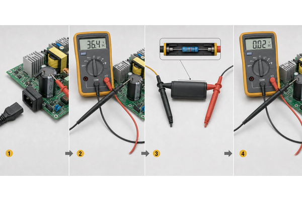
- Isolate every source. Unplug the equipment, disconnect batteries and verify the isolation method required by the service manual.
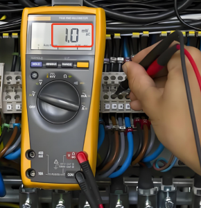
- Measure the capacitor voltage. Select the correct meter function and range. Measure directly across the two capacitor terminals.
- Confirm the discharge tool rating. Check resistance, working voltage, peak power, pulse energy, insulation, probes, and lead condition.
- Connect the resistor across the capacitor. Use insulated clips or probes. Avoid touching terminals, exposed metal, nearby conductors, or heatsinks.
- Keep the resistor connected for the calculated time. Do not use a guessed universal waiting time.
- Remove the discharge tool and measure again. Verify the voltage directly across the capacitor.
- Wait and recheck. Dielectric absorption can cause a small voltage to return after the first discharge.
- Apply the service procedure for continued work. High-energy equipment may require a rated shorting lead or a permanently connected discharge device after the voltage has been reduced; follow the manufacturer’s instructions.
The meter is the verification instrument. The resistor or dedicated discharge tool is the controlled energy-dissipation path.
How Do You Choose the Correct Discharge Resistor?
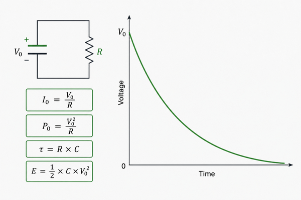
Choose resistance from the allowable initial current and the required discharge time, then verify every resistor rating.
| Check | Formula | What It Controls |
|---|---|---|
| Initial current | I0 = V0 / R |
Probe, wiring, capacitor, and contact stress |
| Initial resistor power | P0 = V0² / R |
Peak heating at connection |
| Stored energy | E = 1/2 × C × V0² |
Pulse energy the resistor network must absorb |
| Time constant | τ = R × C |
Rate of voltage decay |
| Time to target voltage | t = R × C × ln(V0 / Vt) |
Minimum calculated connection time |
For example, a 100 µF capacitor measured at 100 V and discharged through 10 kΩ starts at 10 mA and 1 W. Its time constant is 1 s, and the ideal calculated time to fall from 100 V to 1 V is about 4.6 s. The capacitor initially stores 0.5 J.
This calculation does not by itself approve a resistor. Check the datasheet for maximum continuous working voltage, overload or pulse rating, permissible energy, temperature rise, and derating. A series resistor string may be needed when one component cannot withstand the voltage. Use additional margin for repeated discharge cycles, uncertain capacitance, elevated temperature, or slow cooling.
How Long Does It Take to Discharge a Capacitor?
For an ideal capacitor discharging through a resistor:
V(t) = V0 × e^(-t/RC)
One time constant leaves about 36.8% of the initial voltage. Five time constants leave about 0.67%, but “five time constants” is not a universal safety declaration. The target voltage must come from the equipment procedure and risk assessment, and the final value must be measured.
Real circuits can discharge differently because other resistors, semiconductors, relays, converters, and parallel capacitors change the effective path. Component tolerance and leakage also affect the result. Calculate the expected time, maintain the connection long enough, measure, wait, and measure again.
Can You Discharge a Capacitor with a Multimeter?
A multimeter should normally be used to measure the voltage before and after controlled discharge, not as the primary discharge tool. In voltage mode, a meter commonly has a high input resistance. It may slowly drain a small capacitor, but the time can be impractical and the method is not suitable for unknown or high-energy capacitors.
Do not switch a meter to current, resistance, continuity, diode, or capacitance mode while the capacitor is energized. Those modes are not substitutes for a rated discharge path and may damage the meter or create a hazardous connection. Verify the meter on a known source before and after a critical voltage test when the safety procedure requires it.
Can You Discharge a Capacitor with a Screwdriver or Light Bulb?
Do not use a screwdriver, bare wire, or other metal object to hard-short a charged capacitor. The current is limited mainly by the capacitor’s equivalent series resistance, wiring, and contact resistance. The resulting arc can pit terminals, weld the tool, damage PCB pads, stress the capacitor, scatter molten metal, or cause burns and shock.
A lamp is a resistive load only within a specific operating range. Its cold resistance can be much lower than its hot resistance, and modern LED lamps contain electronic circuits rather than a simple filament. Use a lamp only when an approved equipment procedure specifies the exact load and voltage. A rated resistor network or purpose-built discharge tool is the clearer general method.
How Do You Discharge a Capacitor on a Circuit Board?
Measure and discharge directly across the capacitor terminals or the documented test points. Do not assume that board ground, chassis, and the capacitor’s negative terminal are the same node. This matters in offline switch-mode power supplies, bridge rectifiers, half-bridges, isolated converters, stacked capacitor banks, and floating circuits.
In-circuit components can create parallel discharge paths. They can also reconnect sections through relays, MOSFET body diodes, transformers, or protection networks. Review the schematic when available. If another source can recharge the node, isolate that source before proceeding.
PCB damage often happens when a probe slips between closely spaced pads. Use insulated, mechanically stable probes and avoid scraping solder mask. On a populated PCB assembly, the discharge plan should account for adjacent components, conformal coating, test access, and whether the resistor current can flow through an unintended device.
How Should PCB Designers Add a Bleeder Resistor?
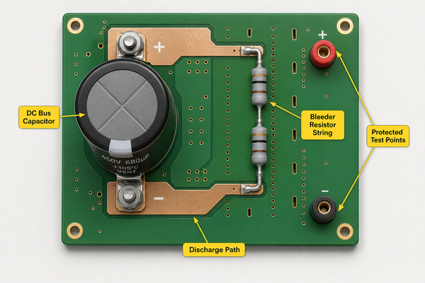
A bleeder resistor is connected across a capacitor or DC bus so voltage falls after power is removed. Its value must balance discharge time against continuous power loss:
Pcontinuous = V² / R
Lower resistance discharges faster but wastes more power and creates more heat during operation. Higher resistance reduces loss but may not meet the required time-to-safe-voltage. The design must also consider tolerance, maximum working voltage, creepage and clearance, pollution degree, resistor failure mode, and whether a single open-circuit failure is acceptable.
For higher bus voltages, use a resistor string when needed to share voltage and heat. Place test points so technicians can verify the actual capacitor voltage without reaching between tall or live components. Keep the discharge path visible in the schematic and service documentation.
Power products may use FR4 PCB manufacturing, a heavy copper PCB, or another special PCB construction. The substrate does not replace the need to check resistor voltage rating, thermal spacing, copper temperature rise, isolation distances, and access for safe measurement.
When Should You Stop and Call a Qualified Technician?
Stop when the voltage, stored energy, circuit topology, service procedure, or required PPE is unknown. Do not improvise on equipment that can contain lethal energy or automatically reconnect power.
Professional service is the correct boundary for microwave ovens, HVAC equipment, mains-input power supplies, motor drives, photoflash circuits, defibrillators, medical equipment, laser power supplies, EV traction inverters, UPS systems, solar inverters, industrial capacitor banks, and damaged high-voltage assemblies. A visibly failed capacitor can vent, rupture, or expose conductive electrolyte; do not approach it as a routine bench component.
FAQ About Capacitor Discharge
1. Do you have to discharge a capacitor before replacing it?
Yes. Isolate all sources, discharge through a controlled rated path, and verify the voltage before desoldering, disconnecting, or touching the terminals.
2. Can you discharge a capacitor by touching it?
No. A person must never be used as the discharge path. Touching the terminals can cause shock, burns, involuntary muscle movement, or a fall.
3. Can a capacitor recharge after being discharged?
Yes. Dielectric absorption can produce a partial voltage rebound after the discharge path is removed. Recheck after a delay and follow the equipment procedure for continued shorting or grounding where required.
4. How long can a capacitor hold a charge?
From seconds to much longer, depending on leakage, capacitance, connected circuitry, temperature, dielectric type, and whether a bleeder resistor is present and functional. Never use elapsed time as proof of zero voltage.
5. Does capacitor polarity change the resistor discharge method?
A resistor works in either current direction, but polarity still matters when measuring a polarized capacitor, identifying circuit nodes, and reconnecting or replacing the part. Follow the meter and equipment instructions.
6. Can a capacitor discharge naturally?
Yes, through internal leakage or external circuit paths, but the rate is uncertain. Verify the voltage instead of relying on natural discharge.
7. Should a new capacitor be discharged before installation?
Check it first. New parts are usually uncharged, but testing, dielectric absorption, static handling, or prior use can leave a voltage. Shorted shipping leads should be removed only according to the manufacturer’s handling instructions.
8. What voltage is safe to touch?
There is no universal touch-safe number for every environment and energy level. Moisture, contact area, current path, frequency, stored energy, and applicable standards all matter. Use the service procedure and verify the required target voltage.
9. Can a temporary discharge resistor stay connected?
Only if the circuit and resistor network were designed for continuous connection. A temporary tool may not have the continuous power, insulation, mounting, or environmental rating required for permanent use.
10. What is the safest capacitor discharge tool?
The suitable tool is rated for the circuit voltage and stored energy, limits current predictably, has touch-safe insulated probes, and allows voltage verification. No single tool covers every capacitor and system.
Conclusion
The safe answer to how to discharge a capacitor is to isolate every energy source, measure the voltage, connect a correctly rated resistor or discharge tool, wait for the calculated interval, and verify twice. Avoid hard shorts, do not treat a multimeter as a universal discharge load, and stop when the circuit or hazard level is outside your training.
For PCB and PCBA projects that need bleeder resistors, protected test points, power-stage layout, prototype assembly, or manufacturing review, contact EBest Circuit (Best Technology) at sales@bestpcbs.com.
You may also like







Tags: bleeder resistor, capacitor discharge, capacitor discharge resistor, capacitor discharge time, capacitor discharge tool, capacitor safety, how to discharge a capacitor