





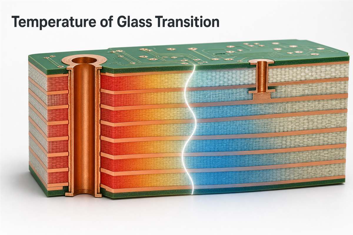
The temperature of glass transition, usually written as Tg, is the temperature region where the polymer resin in a PCB laminate changes from a hard, glass-like condition to a softer, more mobile state. The board does not melt at Tg, but its stiffness and thermal-expansion behavior change enough to affect dimensional stability, plated holes, vias, delamination resistance, and assembly reliability.
Tg is useful only when its test method and the rest of the laminate data are understood. A value measured by differential scanning calorimetry (DSC) may differ from a value measured by thermomechanical analysis (TMA) or dynamic mechanical analysis (DMA). Material selection should therefore consider Tg together with decomposition temperature, time to delamination, Z-axis expansion, layer count, via structure, reflow exposure, and the product environment.
What Is the Temperature of Glass Transition in a PCB?
The temperature of glass transition in a PCB identifies the region where the laminate resin loses much of its glassy stiffness and begins behaving more like a rubbery polymer. Glass reinforcement and copper remain solid, but the resin system becomes more compliant and usually expands faster.
This change matters because copper and resin do not expand at the same rate. Copper barrels, internal pads, resin and woven glass must remain mechanically compatible as the board heats and cools. When the laminate expands excessively through its thickness, plated-through holes and vias carry additional strain.
Tg is not a universal maximum operating temperature. It is one transition property in the laminate datasheet. Continuous-use limits, brief assembly excursions and long-term reliability require other evidence, including the material system, relative thermal index when applicable, thermal-decomposition behavior and the completed assembly design. For a broader definition, see our existing article on what glass transition temperature means.
What Happens Below and Above Tg?
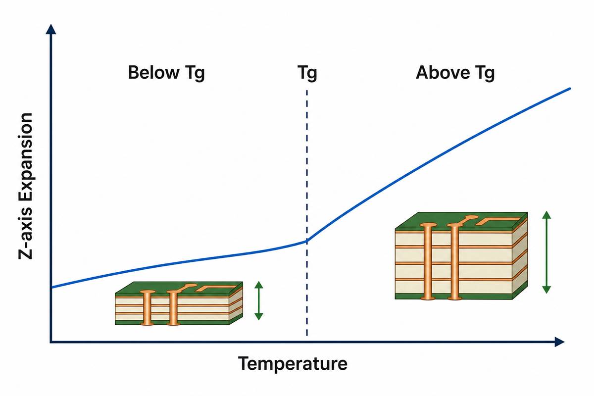
Below Tg, the cured resin is relatively rigid and its molecular segments have limited movement. Above Tg, molecular mobility increases, modulus falls and the laminate’s coefficient of thermal expansion—especially in the Z-axis—normally rises.
| Condition | Resin Behavior | PCB Engineering Effect |
| Well below Tg | Harder and more dimensionally stable | Lower expansion and higher stiffness under the stated test conditions |
| Across the Tg region | Modulus and heat-capacity behavior change | Measurement method identifies a transition point or range |
| Above Tg | Softer and more compliant | Higher Z-axis expansion can increase strain on vias, copper barrels and interfaces |
The transition is not an on-off switch. Real laminate systems show a region rather than one perfectly sharp temperature. Heating rate, thermal history, cure state, moisture, specimen preparation and measurement method can shift the reported value.
How Is Glass Transition Temperature Measured?
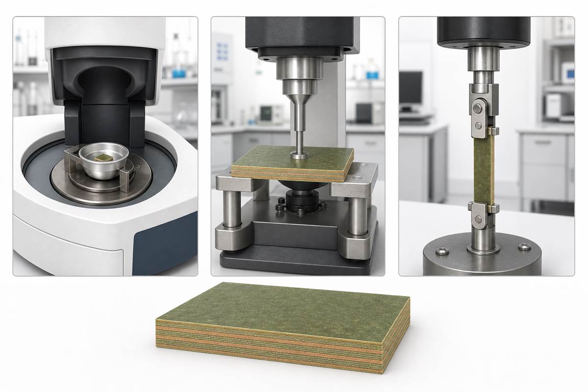
PCB laminate Tg is commonly measured by DSC, TMA or DMA, and the method must be reported with the value. These methods observe different physical responses, so two valid tests can produce different numbers for the same resin system.
| Method | What It Observes | Relevant IPC Method |
| DSC | Change in heat flow across the transition; Tg is commonly reported from the midpoint or steepest deflection | IPC-TM-650 2.4.25 |
| TMA | Change in dimensional expansion; tangent-line intersection identifies Tg and the same scan can quantify Z-axis CTE | IPC-TM-650 2.4.24 |
| DMA | Change in mechanical modulus and damping under an oscillating load | IPC-TM-650 2.4.24.2 or application-specific DMA methods |
IPC notes that DSC and TMA values can differ significantly. DMA results also depend on test frequency, while DSC and TMA results depend on heating rate. A purchase specification that states only “Tg 170°C” is incomplete when the test method and acceptance basis are not defined.
DSC can also compare the first and second heating scans. The difference, often called delta Tg or cure factor, provides information about residual cure under the governing specification. It should not be applied without confirming that the material configuration and test method support that evaluation.
Glass Transition Temperature PCB Chart
A glass transition temperature PCB chart is useful as an initial screening tool, but its labels are market shorthand rather than a complete material specification. Suppliers commonly describe FR-4 as standard Tg, mid Tg or high Tg, yet the boundaries and test methods can differ.
| Common Market Label | Indicative Tg Range | What Must Still Be Checked |
| Standard-Tg FR-4 | Often around 130–140°C | Test method, Td, T288, Z-axis expansion, reflow plan and application temperature |
| Mid-Tg FR-4 | Often around 150–165°C | Material model, laminate construction, total expansion and plated-hole structure |
| High-Tg FR-4 | Often 170°C or higher | Whether the higher Tg also comes with suitable Td, T260/T288, CTE, Dk/Df and processability |
These ranges should never replace a datasheet or controlled drawing. For example, published commercial laminates may report Tg by DSC, TMA or DMA, and the numerical result can move with the method. Compare products using the same measurement basis whenever possible.
Glass Transition Temperature of FR4 PCB
The glass transition temperature of FR4 PCB material depends on its resin formulation, reinforcement, cure state and test method; FR-4 is a material class, not one fixed Tg value. Standard, mid-Tg and high-Tg FR-4 systems can all satisfy the FR-4 designation while offering different thermal performance.
The phrase glass transition temperature FR4 should therefore lead to a material-model check, not a generic assumption. A fabricator needs the laminate family, relevant IPC-4101 slash-sheet requirements when specified, copper-clad construction, prepreg choices and the applicable thermal-property limits.
Our FR-4 PCB material guide explains the broader material properties, while the IPC-4101 overview provides context for laminate and prepreg specifications. Tg remains important, but it is only one part of that material definition.
Why Does Tg Affect Vias and Plated Through Holes?
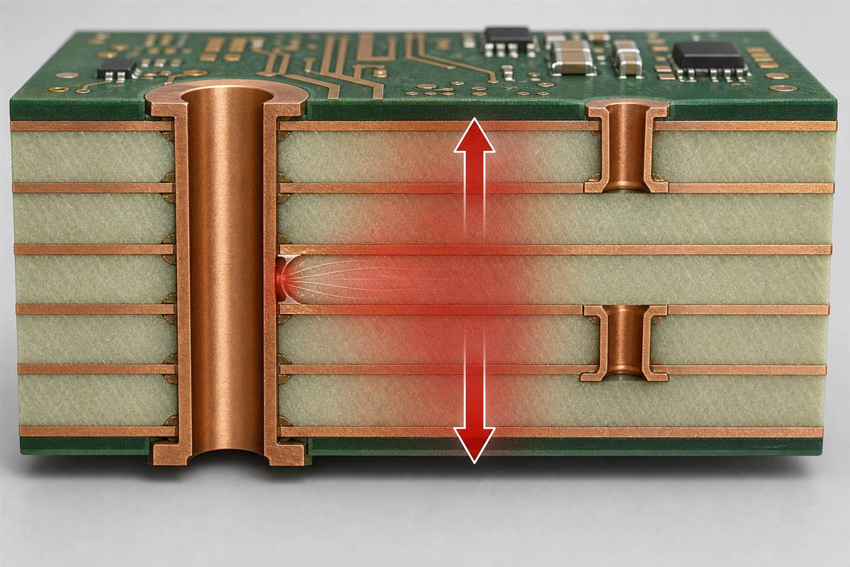
Tg affects vias because the laminate’s Z-axis expansion normally increases above the transition while copper expansion remains much lower. The resulting strain acts on plated barrels, internal-layer connections, microvia interfaces and resin-to-copper boundaries.
Risk becomes more significant when the board has:
- high aspect-ratio plated-through holes;
- thick multilayer constructions;
- stacked or staggered microvias with demanding interfaces;
- multiple lead-free reflow or rework cycles;
- large temperature swings during service;
- moisture exposure before thermal processing;
- weak drilling, desmear, plating or lamination process control.
A higher Tg can reduce the time a board spends in the post-Tg expansion region, but it does not guarantee reliable vias. Post-Tg CTE, total Z-axis expansion, copper plating quality, hole geometry and thermal-cycle count may be equally important. Our article on PCB delamination covers another failure path driven by material, moisture and process interactions.
How Does Tg Relate to Lead-Free Reflow?
Tg helps describe how the laminate behaves during reflow, but it does not need to exceed the brief peak temperature of every soldering profile. PCB laminates routinely experience short excursions above Tg; survival depends on the entire thermal-property set, moisture condition, construction and number of heat cycles.
For lead-free assembly, review at least:
- the reflow profile and expected peak exposure;
- the number of assembly and possible rework cycles;
- Td and time-to-delamination data such as T260 or T288;
- Z-axis CTE below and above Tg;
- total Z-axis expansion over the relevant temperature range;
- board thickness, via geometry and copper distribution;
- storage, baking and moisture-control requirements.
Selecting high-Tg material only because a solder alloy has a high liquidus temperature is incomplete. The laminate datasheet and assembly profile must be reviewed together.
Tg vs Td, T260, and T288
Tg, Td, T260 and T288 answer different thermal questions and should not be treated as interchangeable ratings. Tg describes a change in polymer mobility; Td measures chemical decomposition; T260 and T288 measure how long a specimen resists delamination at fixed temperatures.
| Property | What It Describes | Why It Matters |
| Tg | Transition from glassy to more rubber-like resin behavior | Stiffness and expansion behavior change |
| Td | Temperature associated with a defined percentage of material weight loss by TGA | Indicates the onset of irreversible chemical degradation under the stated method |
| T260 | Time to delamination at 260°C by the specified TMA method | Supports comparison of short high-temperature endurance |
| T288 | Time to delamination at 288°C by the specified TMA method | Provides a more severe fixed-temperature delamination comparison |
| Z-axis CTE / total expansion | Rate or accumulated amount of thickness-direction expansion | Directly relates to strain on plated holes, vias and interfaces |
A high-Tg datasheet can still show an undesirable post-Tg CTE or insufficient delamination time for a specific construction. Conversely, a material with a lower Tg may perform adequately when its overall thermal properties and the product exposure are appropriate.
Is Higher Tg Always Better?
Higher Tg is not always better because it does not automatically improve every electrical, mechanical, processing or cost requirement. Resin systems that achieve a higher Tg may differ in drillability, adhesion, toughness, moisture behavior, cure cycle, Dk, Df and fabrication window.
The correct question is whether the selected laminate provides enough margin and reliability for the completed PCB. A high-Tg material can be justified by repeated thermal cycling, dense multilayer structures, demanding plated holes or elevated-temperature use. A routine design with modest thermal exposure may gain little from an unnecessarily expensive or difficult-to-process material.
Use the lowest-risk qualified material, not simply the highest number on a datasheet. Our overview of high-Tg PCB materials discusses the broader selection context.
How Should Engineers Select Tg for a PCB?
Engineers should select Tg by starting with the board’s thermal and mechanical exposure, then checking laminate data measured on a comparable basis. The decision should consider both fabrication and end use.
- Define the heat exposure: Record assembly profiles, rework allowance, continuous temperature, cycling range and dwell time.
- Review the PCB structure: Check thickness, layer count, via type, aspect ratio, copper distribution and resin-rich areas.
- Compare complete datasheets: Use Tg with Td, T260/T288, pre- and post-Tg CTE, total expansion, moisture data and relevant electrical properties.
- Match the test methods: Avoid comparing one DSC value directly with another supplier’s DMA or TMA value without qualification.
- Confirm fabrication compatibility: Make sure the chosen laminate and prepreg constructions are available and suitable for drilling, lamination, plating and assembly.
- Validate the finished design: Use coupons, cross-sections, thermal stress or product-level cycling when the application risk requires evidence beyond a datasheet.
What Should a PCB Fabrication Drawing Specify?
A fabrication drawing should specify the required laminate or material standard, the Tg value when it is controlling, the measurement method and any other thermal properties needed for acceptance. Writing only “high Tg” leaves room for different interpretations.
Depending on project risk, the controlled notes may include:
- approved laminate manufacturer and material model, or an agreed equivalent process;
- IPC-4101 slash sheet or customer material specification;
- minimum Tg with DSC, TMA or DMA method identified;
- minimum Td or T260/T288 requirement;
- maximum Z-axis CTE or total expansion requirement;
- lead-free assembly, multiple-reflow or special thermal-cycle conditions;
- coupon, cross-section, test report or certificate requirements.
Do not place critical thermal requirements only in an email or quotation note. The released drawing and purchasing specification should identify the acceptance basis.
FAQ About Glass Transition Temperature in PCBs
Is Tg the same as the melting temperature?
No. Tg is a transition in polymer mobility and stiffness, while melting refers to a crystalline phase becoming liquid. An FR-4 PCB remains a solid composite above Tg, although its resin becomes softer and its expansion behavior changes.
What happens at glass transition temperature?
At the glass transition temperature, molecular movement in the cured resin increases. The laminate loses stiffness and its thermal-expansion behavior changes, especially through the Z-axis. The transition occurs across a range rather than at one instant.
What is a typical glass transition temperature for FR-4?
Commercial standard-Tg FR-4 is often described around 130–140°C, mid-Tg material around 150–165°C and high-Tg material at 170°C or higher. These are market ranges, not universal acceptance limits, so confirm the exact material and test method.
Why can DSC and TMA report different Tg values?
DSC measures a heat-flow change, while TMA measures a dimensional-expansion change. They detect different physical responses and use different calculation rules. IPC therefore recommends reporting the equipment or method beside the Tg result.
What does glass transition temperature FR4 mean on a quotation?
It should identify the required FR-4 laminate’s Tg and the method used to measure it. If a quotation lists only “high Tg,” request the material model, datasheet or governing specification so the thermal properties can be compared consistently.
Can a PCB survive a reflow temperature above its Tg?
Yes. PCB laminates can tolerate brief reflow excursions above Tg when their Td, time-to-delamination, expansion, moisture condition and construction are suitable. Tg does not have to exceed the reflow peak, but the full thermal profile must be qualified.
Is high Tg the same as low Z-axis CTE?
No. A higher Tg and a lower Z-axis CTE may occur together in some laminate systems, but one does not guarantee the other. Check pre-Tg CTE, post-Tg CTE and total expansion directly on the datasheet.
What is delta Tg or cure factor?
Delta Tg is the difference between Tg values obtained from first and second DSC scans under the governing test method. It can indicate residual cure for compatible materials, but it should not be applied to every laminate configuration without qualification.
Does Tg determine the maximum continuous operating temperature?
No. Tg describes a material transition, not the complete assembly’s continuous-use rating. Operating limits also depend on insulation systems, relative thermal index where applicable, copper, components, solder joints, coatings, mechanical loads and product qualification.
What information is needed to review a PCB Tg requirement?
Provide the Gerber or ODB++ data, fabrication drawing, stackup, layer count, board thickness, via structure, assembly profile, reflow-cycle count, operating-temperature range, quantity and any required laminate or test-report specification.
How Can EBest Circuit Support Your PCB Material Selection?
At EBest Circuit, we review temperature of glass transition requirements together with the stackup, laminate construction, via geometry, copper distribution, assembly profile and product environment. This helps prevent a single Tg number from being used without the thermal and manufacturing context needed for a reliable PCB.
Send your Gerber files, fabrication drawing, stackup, quantity, thermal conditions and preferred laminate specification to sales@bestpcbs.com. We can review the project requirements and confirm which material details need to be resolved before PCB fabrication or PCBA production.
You may also like




Tags: glass transition temperature fr4, glass transition temperature of fr4 pcb, glass transition temperature pcb, glass transition temperature pcb chart, temperature of glass transition