





An RC receiver board is the electronic control center inside a radio-controlled car, boat, aircraft, robot, or other RC model. It receives wireless commands from a compatible transmitter, validates and decodes those commands, and converts them into control outputs for servos, electronic speed controllers, motor drivers, lights, and auxiliary functions.
The difficult part is not receiving a packet on the bench. It is maintaining a dependable radio link while motors, switching regulators, servos, batteries, and wiring create electrical and mechanical stress. That requires coordinated RF layout, power design, interfaces, firmware, manufacturing control, and system-level testing.
What Is an RC Receiver Board?
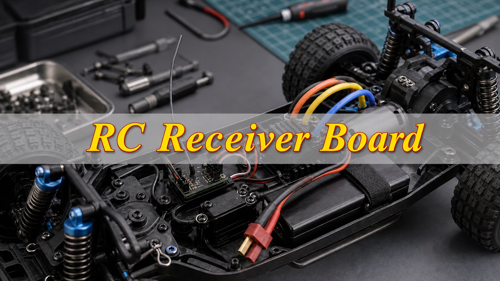
An RC receiver board is a compact radio-frequency and control circuit that converts transmitter commands into electrical control signals used by an RC model. Its antenna and RF front end capture the radio signal, the receiver IC or system-on-chip recovers the data, and a microcontroller or integrated decoder generates outputs for each assigned channel.
In a hobby-grade system, the receiver is often a separate module connected to a steering servo and an electronic speed controller, or ESC. In a toy-grade or space-constrained model, the receiver, motor drivers, voltage regulation, and sometimes stabilization sensors may be integrated on one board. These architectures are not automatically interchangeable.
| Receiver Board Type | Typical Integration | Main Advantage | Key Limitation | Best Fit |
| Standalone receiver | RF receiver and channel outputs | Easy to replace and upgrade | Requires separate ESC or motor controller | Hobby-grade RC cars, boats, and aircraft |
| Receiver and ESC combination | Receiver, speed control, and BEC | Compact wiring and lower system weight | Motor type and current rating are fixed | Small cars and ready-to-run models |
| All-in-one control board | Receiver, motor drivers, steering control, lights, and power | Lowest part count and assembly time | Usually proprietary and difficult to upgrade | Toy-grade and miniature RC models |
| Receiver with stabilization | Receiver plus gyro or other motion sensors | Improved directional or flight stability | Needs correct mounting and calibration | Aircraft, drift cars, crawlers, and high-speed models |
How Does an RC Receiver Board Work?
An RC receiver board works by identifying data from the bound transmitter and translating valid channel values into control outputs. The complete process normally takes place many times per second so that steering and throttle respond smoothly to the operator.
- Capture transmitter input: the transmitter measures the steering wheel, trigger, sticks, switches, or buttons.
- Encode channel data: the processor packages those inputs and transmits them using its supported radio protocol.
- Receive the RF signal: the antenna captures a small portion of the transmitted RF energy.
- Recover the data packets: the RF receiver demodulates the incoming signal.
- Validate each packet: the decoder checks transmitter identity, packet integrity, channel values, and failsafe conditions.
- Generate control outputs: the board sends commands to a servo, ESC, flight controller, motor driver, or auxiliary device.
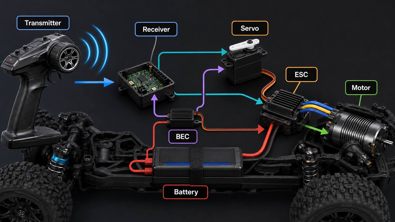
In a modular hobby system, the receiver sends a low-power command to the ESC rather than carrying traction-motor current. The ESC switches the higher battery current required by the motor. Integrated boards may combine these functions, but RF, logic, and power sections still need separate routing, grounding, and noise control.
What Are the Main Components of an RC Receiver Board?
The main components of an RC receiver circuit board are the antenna, RF matching network, receiver IC, processor, power regulation, protection, and output interfaces. The exact architecture depends on protocol, range, channel count, enclosure size, and whether motor control is integrated.
| Component or Circuit | Primary Function | Important Design Concern |
| Antenna | Captures RF energy from the transmitter | Placement, tuning, polarization, enclosure effects, and keep-out area |
| Matching network | Matches antenna impedance to the RF input | Short traces, correct component values, and tuning access |
| RF receiver or transceiver IC | Demodulates incoming packets and may support telemetry | Protocol support, sensitivity, selectivity, and reference layout |
| Crystal or oscillator | Provides an accurate frequency and timing reference | Load capacitance, placement, grounding, and frequency tolerance |
| Microcontroller | Handles binding, channel decoding, failsafe logic, and outputs | Firmware validation, timing, memory, and programming access |
| Regulator or BEC input stage | Generates stable supply rails for logic and RF circuits | Voltage range, ripple, current margin, heat, and transient protection |
| Servo and control ports | Connect steering, throttle, and auxiliary channels | Pin order, signal level, current path, and connector retention |
| Motor driver or ESC stage | Controls brushed or brushless motor current when integrated | Current rating, MOSFET heating, switching noise, and protection |
| Protection components | Limit damage from reverse polarity, ESD, or voltage transients | Protection level without excessive loss or RF loading |
How Does an RC Receiver Board Decode Control Signals?
The board decodes control signals by validating incoming radio packets and mapping channel values to pulse or serial outputs. Only packets that match the receiver’s bound transmitter and pass the protocol’s integrity checks should update the outputs.
Many conventional servos and ESCs accept pulse-width commands. Other systems use combined pulse streams or digital serial buses to carry multiple channels over fewer conductors. The protocol between the transmitter and receiver is separate from the output format between the receiver and the controlled device; matching one does not guarantee compatibility with the other.
Good firmware also manages packet loss. Instead of leaving outputs undefined, it holds the last valid value briefly or moves channels to predetermined failsafe positions. For a car, a safe configuration typically centers steering and removes throttle. The correct behavior must be confirmed for the intended model and application.
How Does a 2.4 GHz RC Receiver Connect to a Transmitter?
A 2.4 GHz RC receiver board connects through a binding process that identifies a compatible transmitter and protocol. After binding, the receiver listens for packets from that transmitter and rejects unrelated radio traffic.
- Confirm protocol compatibility: the transmitter and receiver must support the same protocol, not merely the same 2.4 GHz frequency band.
- Connect regulated power: use the correct voltage and polarity for the receiver.
- Enter bind mode: use the receiver button, bind plug, or documented power-up sequence.
- Start transmitter binding: follow the radio manufacturer’s specified sequence.
- Confirm a stable link: check the receiver status indicator.
- Test every channel: power-cycle both devices and verify operation at close range.
- Verify failsafe behavior: confirm safe output states before operating the model.
- Perform a range test: secure the model and follow the manufacturer’s test procedure.
Frequency alone is not a compatibility standard. Two products labeled 2.4 GHz can still use different modulation, packet structures, hopping sequences, authentication methods, or channel mapping. Before replacing a receiver board for an RC model, verify:
- Radio compatibility: protocol, modulation, transmitter generation, firmware, and binding method.
- Electrical compatibility: supply voltage, signal levels, connector pinout, and output types.
- Mechanical compatibility: board dimensions, mounting points, antenna position, and enclosure clearance.
A receiver manufacturer’s model-specific connection and compatibility manual should remain the primary reference for wiring and supported features.
What Design Requirements Matter for an RC Receiver Board?
A successful RC receiver design must combine RF sensitivity, stable power, interference control, failsafe behavior, and production testability. Range is important, but mechanical durability, manufacturability, and predictable operation beside motors, regulators, servos, and high-current wiring are equally critical.
- RF performance: adequate sensitivity, antenna efficiency, selectivity, and resistance to onboard interference.
- Power integrity: stable rails during servo stalls, throttle changes, battery sag, and ESC switching.
- Electromagnetic compatibility: controlled return paths and separation between RF, digital, and power circuits.
- Mechanical reliability: resistance to vibration, connector stress, shock, moisture, dust, and temperature cycling.
- Functional safety: defined startup, brownout, signal-loss, and failsafe states.
- Production readiness: accessible programming pads, test points, fiducials, inspection clearance, and traceability.
- Size and weight: a board outline and component height compatible with the model and enclosure.
How Should You Design an RC Receiver Board RF Layout?
The RF layout should follow the radio IC and antenna supplier’s proven reference design as closely as the mechanical envelope allows. Small changes in feed length, ground geometry, component placement, enclosure material, or nearby wiring can alter antenna tuning and reduce usable range.
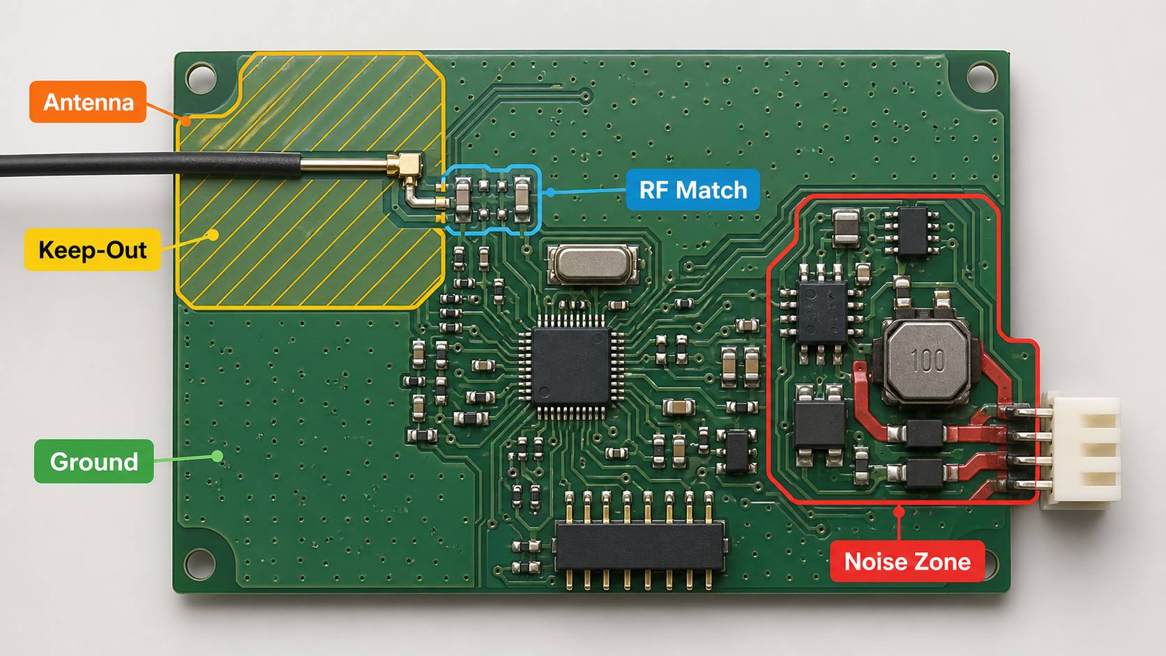
Keep the RF path short, continuous, and isolated from switching noise:
- Matching-component placement: keep components close to the RF pin and antenna feed.
- Controlled impedance: use the geometry defined for the selected stackup.
- Signal continuity: avoid unnecessary vias and sharp impedance discontinuities.
- Noise separation: isolate the RF input from clocks, motor traces, switching nodes, and high-current loops.
Treat the antenna keep-out zone as part of the RF design, not as unused board space:
- Keep-out clearance: exclude restricted copper, components, fasteners, batteries, shielding, and cables.
- Final-enclosure validation: test the antenna in its production installation, not only on an open bench.
- Nearby-material effects: check plastic, carbon fiber, metal chassis parts, and battery placement.
Provide enough measurement access to tune prototypes and control production variation:
- Tuning provisions: include optional matching footprints and accessible RF measurement points.
- Representative prototypes: tune with the final stackup and enclosure.
- Root-cause measurement: combine range testing with impedance and radiated measurements.
- Production control: document approved matching values and test limits.
How Should RC Receiver Power and Control Interfaces Work?
Power, servo, and motor interfaces should be designed around worst-case voltage, current, noise, connector error, and transient conditions. A receiver that works on a bench may still reset in a moving model if servo load or motor switching pulls the supply below the logic threshold.
Power input and regulation:
- Power source: define whether supply comes from an ESC BEC, receiver pack, or onboard regulator.
- Input range: include battery sag, servo stalls, and startup transients.
- Power integrity: use a low-impedance ground return, local IC decoupling, and bulk capacitance near changing loads.
- Input protection: match reverse-polarity, ESD, and transient protection to the connector and use conditions.
- Shared supply and ground: verify the regulated supply arrangement in the relevant receiver connection documentation.
Servo and signal interfaces:
- Pin order: document ground, positive supply, and signal positions.
- Electrical limits: confirm signal thresholds and total current available to connected servos.
- Connector mechanics: specify orientation, locking, spacing, and cable strain relief.
- Misalignment protection: prevent supply voltage from reaching a signal or ground pin.
Integrated motor control:
- Compact switching loops: minimize brushed H-bridge or brushless ESC current paths.
- Worst-case current design: size MOSFETs, gate drive, current sensing, copper, and protection for startup and stall conditions.
- Thermal verification: confirm heat spreading and temperature in the intended enclosure and duty cycle.
- Return-path isolation: keep motor current out of sensitive RF and logic paths.
Which PCB Materials and Stackups Suit RC Receiver Boards?
Standard FR-4 is suitable for many RC receiver boards, while the layer count and laminate grade should be selected according to board size, RF geometry, power density, mechanical stress, and cost. The fabrication stackup must be fixed before final antenna and impedance tuning.
| Option | Typical Use | Advantages | Design Caution |
| Two-layer FR-4 | Cost-sensitive, moderate-density receivers | Low cost and simple fabrication | Ground continuity and RF isolation are harder to maintain |
| Four-layer FR-4 | Compact receivers with dense digital and RF circuits | Better reference planes, routing, and power integrity | Requires a defined impedance stackup and controlled plane splits |
| High-Tg FR-4 | Boards exposed to higher assembly or operating temperatures | Improved thermal and dimensional stability | Material selection should reflect actual temperature requirements |
| Rigid-Flex PCB construction | Very tight packaging or integrated antenna/interconnect shapes | Reduces connectors and fits complex enclosures | Higher cost and stricter bend, coverlay, and assembly controls |
A common compact design uses a four-layer PCB stackup with a continuous ground reference plane. This is not a universal prescription. The RF trace dimensions must be calculated from the fabricator’s actual dielectric thickness, copper thickness, and material properties.
How Are RC Receiver Boards Manufactured and Assembled?
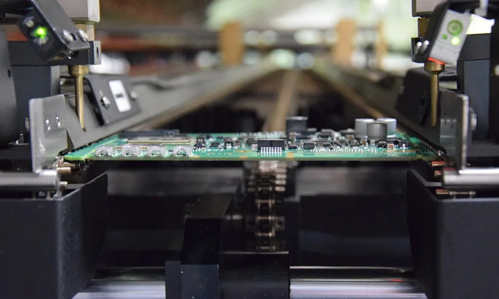
RC receiver boards require controlled PCB fabrication, assembly, inspection, programming, RF verification, and functional testing. Compact RF assemblies need closer control than visual inspection alone can provide.
- Engineering review: verify the stackup, impedance requirements, antenna keep-out, panelization, test points, component availability, and assembly clearances.
- PCB fabrication: image, etch, laminate, drill, plate, apply solder mask, finish exposed pads, route the outline, and electrically test the bare boards.
- Solder-paste printing: control stencil apertures for fine-pitch RF ICs, oscillators, small passives, and thermal pads.
- SMT placement and reflow: place moisture-sensitive and polarity-critical components under documented process conditions.
- Secondary assembly: install through-hole connectors, antenna leads, switches, wires, or shields as required.
- Inspection: use automated optical inspection and targeted X-ray inspection where hidden joints or bottom-terminated packages justify it.
- Programming and calibration: load verified firmware, identifiers, configuration data, and calibration values.
- Functional test: bind, exercise channels, verify output timing, check current consumption, and confirm failsafe operation.
Conformal coating may improve resistance to moisture and contamination, but coating material should not cover unsuitable connectors, switches, test pads, or an antenna region unless its RF effect has been validated. Manufacturing documentation should clearly define masking and coating boundaries.
What Testing Is Required for an RC Receiver Circuit Board?
Testing should verify electrical integrity, RF communication, channel behavior, power stability, and production consistency. A simple bind-and-move test is useful but insufficient for a commercial design.
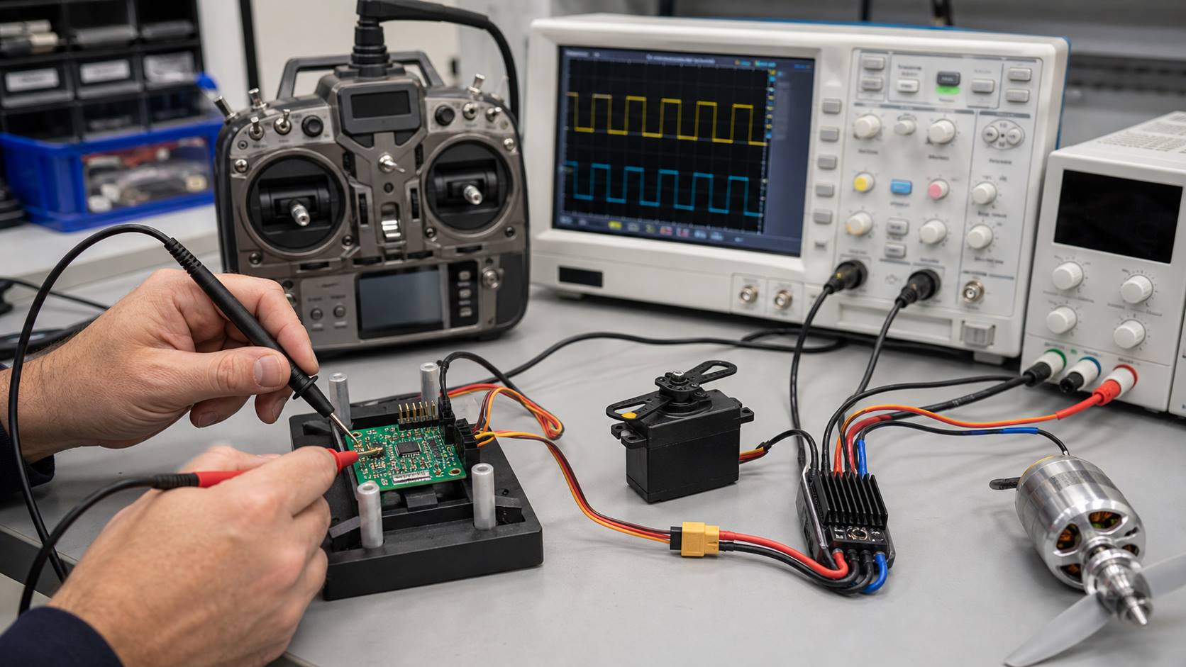
- Bare-board electrical test: checks opens and shorts before assembly.
- Automated optical and X-ray inspection: identifies placement and solder defects, including hidden-joint issues where applicable.
- Programming verification: confirms the correct firmware, configuration, and product identity.
- Power test: measures startup, idle current, rail accuracy, ripple, brownout behavior, and abnormal heating.
- Binding and protocol test: confirms connection to the intended transmitter family and rejection of invalid control data.
- Channel-output test: checks steering, throttle, auxiliary channels, direction, endpoints, latency, and failsafe values.
- RF performance test: evaluates sensitivity, antenna tuning, packet reliability, interference behavior, and controlled operating range.
- Load and noise test: operates servos and motors through realistic acceleration, stall, and switching events while monitoring resets and packet loss.
- Environmental and mechanical test: may include temperature cycling, vibration, shock, humidity, connector retention, or drop testing based on the application.
Test limits should be quantitative and traceable to the design specification. Golden samples, calibrated fixtures, firmware version control, serial tracking, and retained test records make failures easier to contain and investigate.
Why Does an RC Receiver Board Stop Working or Lose Signal?
An RC receiver board usually stops working because of power interruption, protocol mismatch, antenna damage, or RF interference, although connector errors, moisture, physical damage, overheating, firmware problems, and failed components are also possible. Troubleshooting should begin with power and compatibility before replacing the board.
| Symptom | Likely Causes | First Checks |
| No status light or response | No power, reversed polarity, broken connector, failed regulator | Measure input and regulated rails; inspect polarity and wiring |
| Will not bind | Protocol mismatch, wrong procedure, low voltage, firmware mismatch | Confirm exact models and protocol; repeat the documented bind sequence |
| Short or unstable range | Damaged antenna, poor antenna placement, motor noise, detuning | Inspect antenna; separate it from power wiring, metal, and carbon fiber |
| Resets under steering or throttle | BEC overload, voltage sag, insufficient decoupling, ground bounce | Monitor receiver supply during servo stall and rapid throttle changes |
| One channel does not work | Damaged port, wrong channel map, bad cable, output configuration | Swap a known-good device and inspect the signal waveform |
| Intermittent operation after impact or water exposure | Cracked solder joint, contamination, corrosion, fractured antenna feed | Disconnect power, dry and inspect the board, then test under magnification |
Never perform close inspection or rewiring with a drive motor or propeller able to start unexpectedly. Secure the model and remove the pinion or propeller when appropriate, then verify failsafe behavior after any repair.
What RC Receiver PCB Manufacturing Services Can We Provide?
EBest Circuit can provide manufacturability review, PCB fabrication, component sourcing, SMT assembly, inspection, and production planning for custom RC receiver projects. The final service scope and acceptance criteria should be confirmed against the customer’s design files, quantities, test requirements, and approved quotation.
- Engineering review: Gerber, drill, stackup, controlled impedance, panelization, DFM, and DFA.
- PCB fabrication: prototypes, engineering samples, pilot runs, and mass production.
- Component sourcing: approved alternatives and lifecycle-risk review.
- PCB assembly: fine-pitch SMT, through-hole, connectors, wires, shields, and mixed technology.
- Inspection: AOI and targeted X-ray based on package and quality requirements.
- Value-added requirements: programming, traceability, functional testing, coating, and box build reviewed before quotation.
For an accurate engineering review and quotation, submit a complete project package:
- Design files: schematic, PCB source or Gerber/ODB++, fabrication drawing, assembly drawing, and centroid file.
- Component data: BOM with manufacturer part numbers and approved alternatives.
- Firmware: programming file, version, programming method, configuration data, and verification requirements.
- Electrical requirements: transmitter protocol, voltage range, channel outputs, motor or servo loads, and failsafe behavior.
- RF and mechanical context: antenna type, target range, enclosure, chassis, battery position, cable routing, and installation constraints.
- Production requirements: prototype and volume quantities, measurable test limits, traceability, coating, and packaging needs.
FAQs About RC Receiver Boards
Q1: Does an RC receiver board need telemetry?
A1: Telemetry is optional. It is useful when the operator needs live battery voltage, temperature, current, signal quality, or sensor data. It also requires a compatible transmitter, receiver protocol, sensors, firmware, and data interface, so it should be defined before schematic and connector design begins.
Q2: How many channels should a custom RC receiver board provide?
A2: Count every steering, throttle, lighting, switching, stabilization, and auxiliary function, then reserve capacity for likely upgrades. A practical specification includes required channels, spare channels, output format, update rate, and failsafe value for each channel rather than selecting channel count by enclosure space alone.
Q3: How can receiver latency be evaluated?
A3: Measure the time from a controlled transmitter input change to the corresponding receiver output transition with an oscilloscope or logic analyzer. Test typical latency, worst-case latency, jitter, and recovery after packet loss. Use the final protocol settings and representative radio conditions instead of relying only on an average specification.
Q4: When is a diversity antenna useful on an RC receiver board?
A4: Diversity can improve link robustness when model orientation, shielding, carbon-fiber structures, or nearby metal can create antenna nulls. The antennas must have intentional physical separation and different orientation. Adding a second antenna without correct RF architecture, switching logic, and installation validation does not automatically improve range.
Q5: Can one receiver channel control two ESCs?
A5: It may be possible with a suitable splitter, mixer, or controller, but both ESC signal grounds and power arrangements must be compatible. Check whether each ESC includes a BEC. Avoid connecting multiple regulated BEC outputs together unless explicitly supported. Define signal duplication, direction, calibration, and power isolation before wiring.
Q6: What connector details should be included in an RC receiver PCB specification?
A6: Specify the connector series, pitch, pin count, mating part, orientation, polarity, current rating, retention method, and cable length. Include ground, regulated power, signal order, and keying on the drawing. A mechanically compatible connector can still damage the board if its electrical pinout differs.
Q7: How should firmware versions be controlled during receiver-board production?
A7: Release firmware with a controlled filename, checksum, version number, programming settings, and approved configuration data. Link the loaded version to the production lot or serial number. The manufacturing test should confirm firmware identity, successful programming, protected memory settings, and required calibration data before final functional testing.
Q8: What design changes require renewed RF verification?
A8: Recheck RF performance after changing the antenna, matching values, PCB stackup, copper geometry, enclosure, coating, battery location, cable routing, shielding, oscillator, or RF components. Even a mechanically small change can alter tuning. Use documented change control and regression testing before approving the revised board.
Q9: How can production units be screened for inconsistent radio performance?
A9: Combine current-consumption checks, programming verification, packet communication, channel-output testing, and a controlled RF test with defined limits. A repeatable fixture and calibrated reference unit help distinguish assembly variation from setup variation. Record measured results, firmware version, lot information, and failure disposition for traceability.
Q10: What should be included in an RF receiver-board prototype order?
A10: Submit fabrication data, BOM, centroid file, stackup, impedance requirements, antenna information, assembly drawings, firmware, programming instructions, and measurable test criteria. Also identify transmitter protocol, voltage range, channel outputs, enclosure constraints, quantities, and acceptance limits so the prototype can be reviewed as a complete system.
You may also like



Tags: RC receiver board, RC receiver board design, RC receiver board manufacturing, RC receiver circuit board