

A temperature sensor PCB must measure the correct thermal point, not random heat from nearby ICs, copper planes, power traces, or enclosure airflow. For engineers and buyers, accuracy depends on sensor selection, circuit design, PCB layout, material stackup, assembly quality, calibration, and final product testing.
In real projects, many temperature errors do not come from the sensor itself. They come from poor placement, unstable ADC design, wrong thermal path, noisy routing, soldering defects, or missing production test limits. Therefore, a reliable temperature sensor PCB project should be planned from design review to prototype and final assembly.
Are you worried about these problems in temperature sensor PCB projects?
- Measurement drift: Sensor readings may be affected by heat sources, poor placement, copper imbalance, self-heating, enclosure design, or airflow changes.
- Prototype delays: Layout revisions, unavailable sensors, BOM changes, unclear test limits, and repeated sample validation may slow down approval.
- Assembly instability: Reflow stress, wrong orientation, flux residue, weak solder joints, and inconsistent calibration may create batch variation.
As a 20+ years PCB manufacturer, EBest Circuit provides design review, prototype, PCB fabrication, component sourcing, SMT assembly, testing, and global delivery for industrial electronics, IoT devices, power modules, medical equipment, and monitoring systems.
- Design support: We review sensor position, thermal path, ground plane, isolation slot, copper balance, ADC routing, and mechanical clearance before production.
- Prototype control: We support small-batch prototype builds with BOM check, DFM feedback, sample testing, and revision tracking.
- Prototype verification: EBest also supports temperature sensor PCB prototype builds for customers who want to verify accuracy, response time, soldering quality, communication stability, and enclosure influence before mass production.
- Assembly reliability: AOI inspection, reflow profile control, electrical testing, thermal validation, and functional testing help reduce soldering defects and accuracy risks.
Welcome to contact us if you have any request for temperature sensor PCB design, prototype, manufacturing, or assembly: sales@bestpcbs.com.
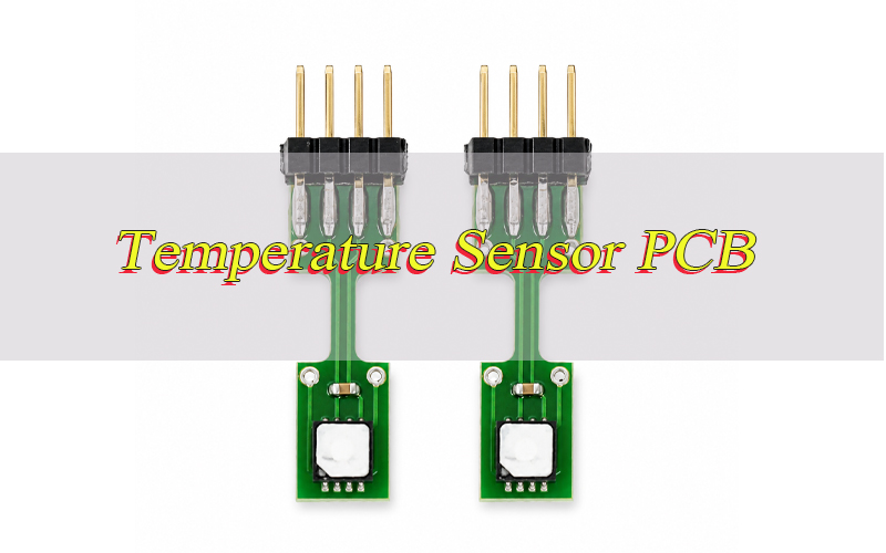
What Is a Temperature Sensor PCB?
A temperature sensor PCB is a printed circuit board that carries a temperature sensing element and supporting circuit to measure board temperature, component temperature, air temperature, liquid temperature, or an external thermal target.
The board may use an NTC thermistor, RTD, thermocouple interface, digital temperature sensor IC, remote diode sensor, or PCB mounted temperature sensor module. The main goal is accurate thermal measurement under real working conditions.
In real products, the PCB is not only a carrier. It becomes part of the thermal system. Copper, FR4, solder mask, vias, enclosure structure, connector position, and nearby heat-generating components all change the final reading.
How Does a PCB Temperature Sensor Work?
A PCB temperature sensor works by converting temperature change into an electrical signal, then sending that signal to an ADC, MCU, comparator, communication IC, or protection circuit.
The sensing method depends on the sensor type. An NTC thermistor changes resistance with temperature. An RTD changes resistance in a more linear way. A thermocouple creates a small voltage from a temperature difference. A digital sensor outputs data through I2C, SPI, 1-Wire, or another digital interface.
After the sensor detects temperature, the circuit filters, converts, compensates, or transmits the signal. Stable measurement depends on both thermal design and electrical design.
What Are the Main Types of Temperature Sensor PCB Boards?
Temperature sensor PCB boards are selected by accuracy, cost, response time, working temperature, interface, size, and target application.
| Type | Range | Accuracy | Interface | Use Case |
|---|---|---|---|---|
| NTC thermistor PCB | -40°C to 125°C | ±0.5°C to ±2°C | Analog | Battery, charger, consumer electronics |
| RTD PCB | -50°C to 250°C+ | ±0.1°C to ±0.5°C | Analog | Industrial control, instruments |
| Thermocouple PCB | -200°C to 1000°C+ | ±1°C to ±3°C | Analog front-end | High-temperature equipment |
| Digital sensor PCB | -40°C to 125°C | ±0.1°C to ±1°C | I2C/SPI/1-Wire | IoT, medical, smart devices |
| Remote diode PCB | -40°C to 125°C | ±1°C typical | IC interface | CPU, FPGA, power IC monitoring |
NTC thermistor boards are cost-effective and compact. Digital sensor boards are easier for firmware integration. RTD and thermocouple boards are better when the project requires wider range, higher temperature, or stronger industrial measurement stability.
Digital temperature sensor PCB designs are suitable for IoT devices, medical electronics, data loggers, and MCU-based products that require direct digital communication. They reduce analog signal conversion work and help engineers read temperature data through I2C, SPI, or 1-Wire interfaces.
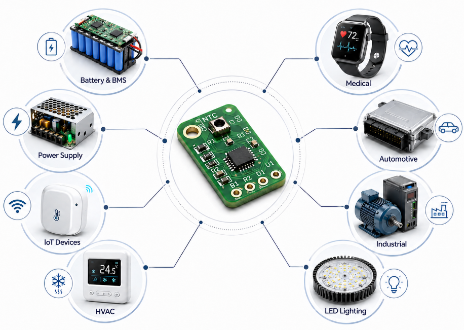
Where Are Temperature Sensor PCBs Commonly Used?
Temperature sensor PCBs are used in products that monitor heat, protect circuits, control systems, or record environmental data.
Common application areas include:
- Battery packs, BMS boards, and charging systems
- Power supply boards, MOSFET modules, and inverter control units
- IoT monitoring devices and smart sensors
- HVAC controllers, thermostats, and air quality devices
- Medical monitoring devices and wearable electronics
- Automotive electronics and thermal protection modules
- Industrial equipment, motor control, and automation systems
- LED lighting, power modules, and high-current PCBA projects
The application decides the layout strategy. Ambient air sensing requires isolation from heat sources. Component temperature monitoring requires strong thermal coupling to the target device.
How to Choose the Right PCB Mounted Temperature Sensor?
Choose a PCB mounted temperature sensor by confirming the measured target, accuracy range, temperature range, response time, interface, package, and assembly process.
- Measured target: Board temperature, air temperature, component temperature, liquid temperature, or enclosure temperature.
- Accuracy level: Use ±0.1°C to ±0.5°C for precision control; use ±1°C to ±2°C for general protection.
- Temperature range: Match the sensor rating with the product’s operating and storage environment.
- Response time: Use better thermal coupling for fast protection; use isolation for stable ambient reading.
- Interface: Analog sensors are low-cost; digital sensors simplify MCU communication.
- Package: SMD packages support automated SMT assembly and compact layout.
- Supply risk: Confirm lifecycle, alternatives, MOQ, and lead time before mass production.
The best sensor is not always the most accurate part on the datasheet. It must match the layout, thermal path, firmware compensation, production process, and final product structure.
How Should You Design a Temperature Sensor PCB Circuit?
A temperature sensor PCB circuit should be designed from the sensing target first, then matched with the right sensor, signal path, power supply, and test method.
Step 1: Confirm the measured temperature point.
Decide whether the circuit measures ambient air, PCB surface temperature, battery temperature, MOSFET heat, motor heat, or enclosure temperature. This decision controls sensor type, placement, copper design, and calibration method.
Step 2: Choose the right sensor type.
Use an NTC thermistor for low-cost protection circuits, an RTD for higher accuracy, a thermocouple for high-temperature areas, or a digital sensor solution for MCU-based products.
Step 3: Design the signal conversion circuit.
For analog sensors, use a stable resistor divider, precision resistor, ADC input, and reference voltage. For digital sensors, confirm I2C, SPI, 1-Wire, address pins, pull-up resistors, and communication voltage level.
Step 4: Add filtering and protection.
Place a small RC filter near the ADC input to reduce noise. Add ESD protection when the sensor connects to an external cable, connector, battery pack, or exposed probe.
Step 5: Stabilize the power supply.
Place a 0.1µF decoupling capacitor close to the sensor IC. Keep the sensor supply away from noisy switching regulators, high-current traces, motors, relays, and fast digital lines.
Step 6: Control self-heating.
Reduce sensor current when using thermistors or RTDs. Excess current can warm the sensor itself and create a false high reading, especially in compact or low-airflow products.
Step 7: Leave space for testing and calibration.
Add test pads for sensor output, supply voltage, ground, ADC input, or communication lines. For precision products, reserve calibration data in firmware or production test records before mass assembly.
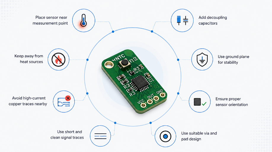
How Should You Layout a Temperature Sensor PCB for Accurate Measurement?
A temperature sensor PCB layout should control heat flow, electrical noise, sensor position, and assembly clearance. The main rule is to place the sensor where the real temperature must be measured, then block unwanted heat from changing the reading.
A good temperature sensor PCB layout should separate the sensing area from unrelated heat sources while keeping the sensor close to the real thermal target. This layout approach helps reduce thermal offset, unstable readings, and slow response during real product operation.
- Confirm the measurement target first.
If the sensor measures ambient air, place it near airflow and away from hot components. If it measures MOSFET, battery, regulator, or LED temperature, place it close to the heat source with a short thermal path. - Keep the sensor away from false heat sources.
Do not place the sensor near processors, DC-DC converters, MOSFETs, power resistors, transformers, relays, LED drivers, or high-current traces unless those parts are the measured target. - Use copper based on the measurement purpose.
For component temperature monitoring, copper planes and thermal vias help transfer heat to the sensor. For ambient air measurement, reduce copper around the sensor to avoid heat spreading from the board. - Add slots, cutouts, or isolation gaps when measuring air temperature.
A small slot or thermal isolation gap can reduce heat conduction from the main board area. This helps the sensor follow air temperature instead of board temperature. - Place thermal vias under or near the heat source when tracking component temperature.
If the sensor is mounted on the opposite side of a MOSFET or power IC, thermal vias can transfer heat through the board and improve response speed. - Keep analog sensor traces short and clean.
Route thermistor, RTD, and ADC traces away from switching nodes, clock lines, motor traces, antenna areas, and high-current paths. Short traces reduce noise and improve reading stability. - Use a solid ground reference for sensitive circuits.
A stable ground plane helps reduce ADC noise and signal fluctuation. However, avoid large copper areas around an ambient sensor if they transfer unwanted heat. - Place decoupling capacitors close to digital temperature sensor ICs.
A 0.1µF capacitor should be close to the sensor power pin. This helps prevent supply noise from affecting I2C, SPI, or 1-Wire communication. - Reserve test points near the sensor circuit.
Add test pads for sensor output, power, ground, ADC input, and communication lines. This makes prototype debugging, production testing, and failure analysis faster. - Check enclosure airflow before finalizing the layout.
Plastic housing, vents, sealing material, battery position, and airflow direction can change the sensor reading. The layout should be tested inside the final enclosure, not only on an open bench.
How to Improve Temperature Measurement Accuracy on a PCB?
Temperature measurement accuracy improves when the board controls thermal interference, electrical noise, mechanical stress, and calibration error at the same time.
- Place the sensor near the correct target: Wrong position creates systematic error that calibration cannot fully fix.
- Control copper around the sensor: Copper can transfer heat quickly, so use it for coupling or reduce it for isolation.
- Separate heat sources: Regulators, processors, relays, and power resistors should stay away from ambient sensors.
- Use stable reference components: Low-tolerance resistors and stable ADC reference improve analog measurement.
- Reduce self-heating: Lower duty cycle and sensor current where the sensor warms itself.
- Validate in the final enclosure: Airflow, plastic housing, vents, dust, and sealing materials affect actual readings.
- Calibrate samples before batch production: Thermal chamber or reference thermometer testing catches offset early.
Accuracy is a system result, not a sensor-only specification.
What Materials Are Used for Temperature Sensor PCB Boards?
Temperature sensor PCB materials are selected by thermal behavior, temperature range, insulation, cost, and application environment.
| Material | Conductivity | Temperature Fit | Use Case |
|---|---|---|---|
| FR4 | 0.25 W/m·K | General electronics | IoT, control boards, monitors |
| Copper | 385 W/m·K | Thermal transfer | Heat coupling, ground plane, vias |
| Solder mask | 0.245 W/m·K | Surface protection | Standard PCB protection |
| Aluminum base | 150–220 W/m·K | Heat spreading | LED, power, thermal modules |
| Polyimide | 0.12–0.2 W/m·K | Flexible circuits | Wearables, compact sensors |
| High-Tg FR4 | 0.25 W/m·K | Higher heat resistance | Automotive, industrial PCBA |
| Rogers material | Varies | RF and stable dielectric | Wireless sensor modules |
Copper is useful when the sensor must follow a heat source quickly. FR4, slots, air gaps, and thinner structures help when the sensor must avoid board heat and measure ambient air.
What Should Be Checked Before Temperature Sensor PCB Assembly?
Before temperature sensor PCB assembly, the design file, BOM, sensor footprint, polarity, process limits, and test method should be checked together. Most assembly problems can be prevented before SMT starts.
- Check the sensor part number and approved alternatives.
Confirm sensor type, package, tolerance, temperature range, accuracy, communication interface, lifecycle, MOQ, and lead time. Avoid last-minute BOM replacement without engineering approval. - Check the footprint and pad size.
Compare the PCB footprint with the sensor datasheet. Wrong pad size may cause tombstoning, poor wetting, offset placement, open solder joints, or weak mechanical strength. - Check polarity and orientation marks.
Digital temperature sensors, thermocouple interface ICs, and some sensor modules have fixed orientation. Silkscreen marks, pin 1 marks, and CPL data should match the assembly drawing. - Check resistor tolerance in analog sensor circuits.
For thermistor and RTD circuits, resistor tolerance directly affects measurement accuracy. Use precision resistors when the project requires stable readings. - Check ADC reference and filtering components.
Confirm the ADC input path, reference voltage, RC filter, pull-up resistor, and protection circuit. Missing or wrong values can create unstable temperature readings. - Check communication lines for digital sensors.
Confirm I2C, SPI, or 1-Wire pull-up values, address settings, voltage level, trace length, and MCU pin mapping before assembly. - Check solder paste and stencil design.
Small SMD sensors require controlled paste volume. Too much paste can lift the component, while too little paste can create weak joints or intermittent readings. - Check reflow temperature compatibility.
Confirm whether the sensor can tolerate the planned reflow profile. Some precision sensors may drift after thermal stress, so reflow profile control is important. - Check conformal coating or waterproof process.
Coating can slow sensor response and change air temperature readings. If coating is required, define coating keep-out areas or validate coated samples before mass production. - Check production test limits before assembly.
Define pass/fail limits for resistance, voltage, ADC value, communication response, temperature offset, and functional output. Clear limits prevent subjective inspection after production.
How Do We Test a Temperature Sensor PCB After Assembly?
Temperature sensor PCB testing should verify soldering quality, circuit function, communication stability, temperature response, and measurement accuracy. Testing must prove that the assembled board works under real operating conditions.
- Start with visual inspection.
Inspect sensor placement, orientation, solder joint shape, missing parts, bridges, contamination, board damage, and connector quality. This catches visible defects before power-on testing. - Use AOI for SMT placement control.
AOI checks sensor offset, polarity, tombstoning, solder bridges, insufficient solder, and missing components. It is especially useful for small SMD sensors and compact layouts. - Check resistance or voltage output.
For thermistor and RTD circuits, measure resistance, divider voltage, ADC input voltage, and ground continuity. Abnormal values usually indicate wrong components, poor soldering, or circuit damage. - Check digital communication.
For digital sensor designs, test I2C, SPI, or 1-Wire response. Confirm device address, communication stability, data output, and MCU reading under powered operation. - Run functional temperature testing.
Power the assembled board and compare the sensor reading with a reference thermometer, thermal chamber, hot plate, or controlled temperature source. - Test at more than one temperature point.
A single room-temperature reading may not show offset, drift, or response problems. Common checkpoints include 25°C, 60°C, and 85°C, depending on the application. - Check response time.
Move the board from one temperature condition to another and record how quickly the reading changes. Slow response may indicate poor thermal contact, thick coating, wrong placement, or weak copper coupling. - Check stability under load.
Test the board while processors, regulators, MOSFETs, LEDs, motors, or wireless modules are running. This confirms whether internal heat or electrical noise affects the sensor reading. - Perform sampling or 100% testing based on project risk.
Simple protection circuits may use sampling tests. Medical, industrial, battery, automotive, and power-control projects often require stricter functional checks. - Record test data for batch traceability.
Keep records for test temperature, measured value, tolerance limit, firmware version, batch number, and operator result. Traceability helps solve field complaints faster.
What Problems Can Occur in Temperature Sensor PCB Design and Layout?
Temperature sensor PCB problems usually come from wrong placement, poor thermal path, electrical noise, weak soldering, or missing validation. Each problem should be solved by layout control, circuit correction, process control, or test verification.
- Problem: False high temperature reading.
The sensor may be too close to a regulator, processor, MOSFET, LED driver, transformer, or high-current trace.
Solution: Move the sensor away from unrelated heat sources, reduce nearby copper, add isolation slots, and test inside the final enclosure. - Problem: Temperature response is too slow.
Thick FR4, poor copper contact, coating, plastic housing, or long thermal distance can delay heat transfer.
Solution: Shorten the thermal path, add thermal vias, increase copper coupling to the target, and avoid coating over fast-response sensing areas. - Problem: Ambient temperature reading is unstable.
Airflow changes, enclosure vents, board heat, and large copper planes may create unstable readings.
Solution: Place the sensor near controlled airflow, isolate it from hot board areas, and validate readings in the final housing. - Problem: ADC value is noisy.
Long analog traces, switching power supply noise, unstable reference voltage, and poor grounding can affect thermistor or RTD signals.
Solution: Shorten analog traces, add RC filtering, use a stable reference, separate noisy routes, and keep the sensor circuit close to the ADC. - Problem: Digital sensor communication fails.
Wrong pull-up resistors, address conflict, long I2C bus, voltage mismatch, or ESD damage can stop data transmission.
Solution: Check pull-up values, confirm address pins, match voltage levels, add ESD protection, and test communication before batch approval. - Problem: Batch readings vary too much.
Sensor tolerance, resistor tolerance, reflow drift, solder quality, and missing calibration can create batch variation.
Solution: Use controlled-tolerance components, verify reflow profile, add calibration data when required, and define production test limits. - Problem: Sensor is damaged during assembly.
Excessive reflow temperature, poor stencil design, wrong orientation, or handling stress may damage the sensor.
Solution: Follow the sensor datasheet, control solder paste volume, check CPL orientation, and inspect first-article samples before mass SMT. - Problem: Reading changes after coating or potting.
Coating and potting materials may block airflow, slow response, or transfer heat differently.
Solution: Set coating keep-out areas when required, test coated samples, and compare coated versus uncoated temperature response before approval.
How to Choose a Temperature Sensor PCB Manufacturer?
Choose a temperature sensor PCB manufacturer by checking whether they can control design review, fabrication, assembly, component sourcing, testing, and batch traceability. A reliable supplier should reduce measurement risk before production starts.
- Check whether the factory understands thermal layout.
The manufacturer should review sensor placement, heat source distance, copper area, thermal vias, isolation slots, and enclosure influence. A normal PCB supplier may only check manufacturability, but temperature sensing boards require thermal judgment. - Check whether they support DFM and DFA review.
DFM checks fabrication risks such as copper clearance, vias, solder mask, slot design, and panelization. DFA checks assembly risks such as footprint, stencil opening, polarity, soldering access, and component spacing. - Check whether they can source stable sensor components.
Temperature sensor projects are sensitive to tolerance and batch consistency. The supplier should confirm original part availability, alternative models, lead time, MOQ, and lifecycle before quoting mass production. - Check whether they can build prototypes before mass production.
Prototype assembly helps confirm accuracy, response time, enclosure effect, solder quality, and firmware reading. A manufacturer that supports prototype and mass production together reduces handover mistakes. - Check whether they can perform functional testing.
A strong supplier should support AOI, electrical testing, communication testing, powered functional testing, and temperature comparison. For precision projects, thermal chamber or controlled temperature validation should be available. - Check whether they define measurable quality standards.
Ask for inspection criteria, sample approval process, test limits, failure handling method, and batch records. Clear standards are more credible than general promises about quality. - Check whether they understand global B2B delivery.
For overseas buyers, the manufacturer should provide export packaging, clear communication, engineering feedback, production tracking, and global shipment from China without claiming fake local warehouses or overseas factories. - Check whether they can support revision control.
Temperature sensor PCB projects often go through layout revisions after testing. The supplier should track Gerber version, BOM version, CPL version, firmware notes, and test records to avoid mixed production files. - Check whether they can explain risks before quotation approval.
A credible manufacturer will point out unclear BOM items, risky sensor placement, missing test limits, coating concerns, and component lead-time risks before production. Engineering feedback is often more valuable than a low price with no review.
Why Choose EBest for Temperature Sensor PCB Assembly?
EBest helps customers reduce temperature measurement risk, shorten prototype time, and control assembly quality for temperature sensor PCB projects. We support PCB design review, PCB prototype, component sourcing, PCB assembly, testing, and mass production.
- Reduce design and layout risk
We check sensor placement, heat source distance, copper distribution, thermal vias, isolation slots, ADC routing, and test-point access before production. This helps reduce false readings, slow response, and unstable output. - Support prototype verification before mass production
We help customers build samples first, then verify temperature response, soldering quality, communication stability, and enclosure influence before approving batch assembly. - Control component sourcing quality
We check sensor model, package, tolerance, approved alternatives, lead time, and BOM consistency. This helps reduce shortage risk, wrong part selection, and batch variation. - Improve assembly reliability
We review footprint, polarity, stencil opening, solder paste volume, reflow compatibility, and coating requirements before SMT assembly. This helps prevent tombstoning, poor solder joints, wrong orientation, and sensor drift. - Provide practical production testing
We can support AOI inspection, electrical testing, functional testing, communication testing, and temperature comparison according to project requirements. This helps customers confirm that the assembled board works under real operating conditions. - Support certified production control
EBest supports ISO 9001:2015, IATF 16949, ISO 13485:2016, AS9100D, REACH, RoHS, and UL-related project requirements. This is useful for industrial, medical, automotive, and high-reliability temperature sensing applications. - Help customers move faster from sample to batch order
With prototype, assembly, testing, and mass production in one workflow, customers can reduce supplier handover problems and keep engineering changes easier to manage. - Offer global delivery from a China source factory
Customers get direct factory communication, flexible customization, controlled production, export packaging, and global shipment without unnecessary middle suppliers.
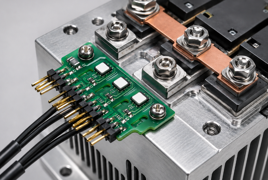
Case Study: Industrial Temperature Sensor PCB for Power Module Monitoring
Project background
The customer required a temperature sensing board for an industrial power control module. The board included MOSFETs, a switching regulator, current-sensing components, and a digital sensor connected to the MCU through I2C.
Project requirements
- Monitor MOSFET temperature during continuous high-load operation.
- Reduce false readings caused by nearby regulator heat.
- Keep sensor communication stable through I2C.
- Improve response speed without increasing board size.
- Support prototype testing before batch assembly.
Main difficulties
- The original sensor position was too close to the switching regulator.
- Copper around the regulator transferred unwanted heat to the sensor area.
- The enclosure had limited airflow, which made heat accumulation more obvious.
- Dense routing limited the available space for sensor relocation.
- The first layout lacked enough test points for production verification.
EBest solution
- Moved the sensor closer to the MOSFET thermal path.
- Separated the sensor area from the regulator copper area.
- Added thermal vias near the MOSFET to improve heat transfer.
- Checked the sensor footprint, pin 1 direction, stencil opening, and solder paste volume.
- Added test pads for power, ground, SDA, SCL, and sensor output verification.
- Performed AOI inspection, powered functional testing, and temperature comparison after assembly.
Output result
- The revised board reduced false high readings from regulator heat.
- The sensor responded faster to MOSFET temperature changes.
- I2C communication remained stable during powered testing.
- The customer approved the pilot batch after thermal and functional validation.
- The final design measured the intended heat source instead of nearby unrelated board heat.
FAQs About Temperature Sensor PCB Board
Q1: Does sensor package size affect response speed?
A1: Yes. Smaller packages usually respond faster because they have less thermal mass, but they may be harder to assemble and inspect. Larger packages are easier to solder and handle, but response may be slower. For compact boards, package size should be selected together with placement and copper design.
Q2: Can one board use both an NTC thermistor and a digital sensor?
A2: Yes. Some designs use an NTC thermistor for protection and a digital sensor for data reporting. This can improve safety and system monitoring, but it also increases BOM cost, layout space, firmware work, and test complexity.
Q3: What tolerance is acceptable for industrial temperature monitoring?
A3: General industrial monitoring often accepts ±1°C to ±2°C. Precision control may require ±0.1°C to ±0.5°C. The final tolerance should include sensor tolerance, resistor tolerance, ADC error, thermal offset, calibration method, and enclosure effect.
Q4: Does PCB thickness affect thermal response?
A4: Yes. A thicker board can slow heat transfer, especially when the sensor tracks a component on the opposite side. A thinner board, copper coupling, and thermal vias can improve response. For ambient sensing, slower heat transfer may help reduce board heat influence.
Q5: When should calibration be added in production?
A5: Calibration should be added when the product requires tight accuracy, multi-point temperature control, medical monitoring, battery protection, or industrial alarm limits. Common calibration points include 25°C, 60°C, and 85°C, depending on the working range and customer requirement.
Q6: Can the sensor be placed under a battery cell?
A6: Yes, but the mechanical structure must be controlled. The sensor should have stable contact with the battery surface without excessive pressure. Insulation, adhesive, spacing, and assembly tolerance should be checked to avoid damage or inconsistent readings.
Q7: Why does the reading change after the product is assembled into the enclosure?
A7: The enclosure changes airflow, heat storage, vent direction, and thermal contact. Plastic walls, sealing foam, batteries, displays, and nearby cables can all affect the reading. Final validation should be performed in the complete product structure.
Q8: How many test points should be reserved for debugging?
A8: At minimum, reserve test points for power, ground, sensor output, and communication lines. For digital sensors, SDA and SCL should be accessible. For analog circuits, ADC input and divider voltage should be measurable. This reduces debugging time during prototype and production testing.
Q9: Does solder mask color influence the measured temperature?
A9: In most standard electronics, solder mask color has limited effect. However, in optical heating, outdoor exposure, or infrared-related products, surface color and coating can influence heat absorption. For sensitive products, test the final surface finish under real use conditions.
Q10: Can waterproof glue or potting compound change response time?
A10: Yes. Glue, coating, and potting compound can slow response and shift readings because they change heat transfer and airflow exposure. If waterproofing is required, coated and uncoated samples should be compared before final process approval.
Q11: How can buyers avoid inconsistent readings between batches?
A11: Use approved component brands, controlled-tolerance resistors, stable sensor models, clear reflow requirements, fixed test limits, and recorded calibration data. Batch consistency depends on both materials and process control, not only the sensor datasheet.
Q12: When should multiple sensors be used on one product?
A12: Multiple sensors should be used when the board has separate heat zones, battery cells, power devices, processors, or enclosure hot spots. One sensor can report general board temperature, but it cannot accurately represent every thermal point in a dense product.
Q13: What factors can delay prototype approval?
A13: Common delay factors include unclear BOM alternatives, wrong footprint, missing CPL data, unavailable sensors, no test limits, enclosure changes, firmware mismatch, and late thermal validation. Prototype approval is faster when design files, test rules, and target conditions are confirmed early.
Conclusion
Temperature sensor PCB accuracy depends on the full system: sensor type, thermal path, PCB material, copper design, placement, assembly quality, enclosure structure, and testing method. For design selection, define whether the board measures air, board, component, or external target temperature before choosing the sensor and layout strategy.
For procurement, choose a manufacturer that can review the layout, control fabrication, assemble the board, source stable components, and verify sensor output after production. EBest Circuit provides custom design review, prototype, assembly, testing, and global delivery from China source factory. Send your files and project details to sales@bestpcbs.com.
You may also like


Tags: temperature sensor PCB board, Temperature Sensor PCB Design, temperature sensor PCB layout