





A body control module (BCM) manages vehicle body electronics such as lighting, central locking, wipers, and accessory power. It receives switch and network inputs, applies programmed logic, and controls electrical loads directly or through other modules. Testing begins with the vehicle’s power supply, grounds, wiring, and communication network before moving to the controller itself.
At EBest Circuit, we support PCB fabrication, component sourcing, assembly, and project-defined testing for automotive electronics. For a BCM PCB project, the manufacturing review connects the board layout, power circuits, connectors, firmware, and test requirements so the assembled hardware can be checked against the intended operating conditions.

Key Takeaways
- A body control module coordinates vehicle body functions, including lighting, door locks, wipers, and accessory power; its exact responsibilities depend on the vehicle architecture.
- The BCM is one type of electronic control unit, while an engine control module primarily manages engine operation.
- BCM locations vary by vehicle, with common mounting areas near an interior fuse panel, beneath the dashboard, or behind a kick panel.
- Irregular lighting, failed locks, communication faults, and battery drain can involve the BCM, but the same symptoms can originate in wiring, power supplies, switches, or connected loads.
- BCM replacement may require programming, vehicle configuration, or security-related initialization; compatibility depends on more than matching the connector shape.
- Test a suspected BCM by recording faults, checking power and grounds under load, reviewing network communication, and comparing input data with commanded outputs.
- Reliable BCM PCB design balances protected power inputs, low-resistance load paths, stable logic supplies, controlled signal returns, and mechanical support.
- BCM production testing should verify the assembled circuits, firmware, communication, load control, and sleep behavior against an approved test specification.
What Does a Body Control Module Do?
A body control module coordinates electrical functions associated with vehicle access, lighting, comfort, and body operation. Depending on the platform, it may switch a load directly, energize a relay, or send a command to a separate controller.
For example, opening a door may trigger several coordinated actions: the courtesy lamp turns on, the instrument cluster receives a door-open message, and the alarm system updates its state. The BCM processes the relevant inputs and determines which actions are appropriate.
| Function Area | Typical BCM Responsibility | Related Inputs or Loads |
| Interior lighting | Controls courtesy lighting, dimming, and timed shutoff | Door switches, lamp circuits, dimming commands |
| Exterior lighting | Coordinates selected lighting functions and fault monitoring | Lighting switches, lamp drivers, network requests |
| Vehicle access | Manages locking requests and door-status information | Lock switches, latch sensors, actuators |
| Wipers and washers | Coordinates operating modes and timing | Stalk inputs, rain-sensor messages, motors or relays |
| Accessory power | Controls selected power states and delayed shutdown | Ignition status, accessory requests, switched outputs |
| Security coordination | Exchanges access and authorization information where assigned | Key receiver, alarm sensors, other vehicle controllers |
| Network communication | Shares body-system status and commands | CAN, LIN, and platform-specific interfaces |
The BCM’s responsibility depends on the vehicle’s electrical architecture. A function listed above may belong to a dedicated door, lighting, or access controller on another vehicle.
This distinction matters during troubleshooting. A window that stops moving may involve a local door module and motor circuit even when the BCM participates in the overall command sequence.
Where Is the Body Control Module Located?
The BCM is commonly installed near an interior fuse panel, beneath the dashboard, behind a kick panel, or in another protected location close to the body wiring harness.
Some vehicles combine body-control electronics with a junction or fuse-box assembly. Others use a separate enclosure with several harness connectors. The appearance and mounting position can change between model years and equipment variants.
Use the vehicle identification number, wiring diagram, and component-location information to identify the correct module. A connector photograph from a similar vehicle provides less certainty than the specified part number and connector designation.
Before access or removal, follow the vehicle’s shutdown and battery-isolation procedure. Nearby harnesses may serve restraint systems or other circuits with separate handling requirements.
For a new BCM design, mounting location also establishes engineering requirements. An enclosed cabin installation and a location exposed to condensation or splash demand different enclosure, connector, and environmental protection strategies.
What Are the Symptoms of a Faulty Body Control Module?
Possible symptoms include inconsistent lighting, intermittent locking, unexpected accessory operation, communication faults, or excessive parked-vehicle current. Several affected functions may point toward a shared supply, ground, network connection, or controller.
Symptoms identify the circuit to investigate; measurements establish the cause.
A single failed lamp or actuator often calls for local circuit checks first. Multiple unrelated functions failing together make shared electrical connections especially relevant.
| Observed Symptom | Possible BCM-Related Cause | Other Causes to Check | Useful Diagnostic Evidence |
| Several body functions stop together | Missing module supply, internal reset, or controller fault | Shared fuse, ground connection, harness damage | Supply voltage and ground drop during the event |
| One lamp or actuator fails | Output-driver or command problem | Failed load, connector damage, open wiring | Command status, output voltage, load current |
| Locks operate intermittently | Input-processing or output-control issue | Latch switch, door harness, actuator mechanism | Live input data and commanded-output response |
| Communication with the BCM is lost | Supply, wake-up, transceiver, or internal fault | Network wiring, gateway state, another affected node | Network scan, power checks, waveform capture |
| Battery discharges while parked | Module remains awake or keeps an output active | Other awake modules, accessories, battery condition | Current trend after the prescribed shutdown period |
| Fault appears during cranking | Module resets as its supply falls | Battery weakness, resistive power or ground connection | Voltage capture at the module during cranking |
| Fault follows rain or washing | Moisture reaches electronics or connectors | Harness leakage path, enclosure or seal damage | Inspection linked to the affected circuit |
The timing of the fault is valuable evidence. Record whether it occurs during cranking, after unlocking, with a particular load operating, after warming up, or following moisture exposure.
That information helps reproduce the condition and separates a continuous hardware fault from an intermittent electrical or software-state problem.
How Do You Test a Body Control Module?
Test the BCM in a sequence that establishes its operating conditions before judging its outputs. Use the applicable wiring diagram, diagnostic procedure, and a scan tool that supports the vehicle’s body systems.
1. Record the complaint and diagnostic information.
Save diagnostic trouble codes, module identification, software information, and relevant status data before clearing faults. Scan related modules as well, since they may record communication loss or supply disturbances affecting the BCM.
A generic engine-code reader may provide limited access to body-system information. Confirm tool coverage before interpreting missing data as a vehicle fault.
2. Check the battery supply and fuses.
Confirm battery condition and inspect the BCM’s specified feeds. A controller may have separate permanent, switched, and load-power connections.
Measure the supply at the module when the problem occurs. Voltage measured at an unloaded connector can look normal even when a resistive connection limits current during operation.
3. Measure ground and supply voltage drop under load.
Check the relevant paths while the circuit is operating, using suitable back-probing methods and the manufacturer’s limits.
For illustration, a connection with 0.10 Ω resistance carrying 3 A produces:
Voltage drop = I × R = 3 × 0.10 = 0.30 V
The same connection dissipates 0.90 W. This example shows why a connection that passes a basic continuity check can still affect operation under load.
4. Inspect connectors and harness sections.
Look for backed-out terminals, corrosion, loose locks, damaged seals, and harness stress. Link each finding to the pin and circuit involved.
Connector condition matters especially where the complaint changes with vibration, door movement, or temperature.
5. Compare live inputs with the actual vehicle state.
Operate the relevant switch or latch and observe the corresponding data. If the BCM reports a door as open while it is physically closed, investigate that input path before replacing the controller.
6. Command the output and measure the response.
Where supported, use controlled actuator tests to compare the requested action with output voltage and current. Keep moving parts clear and follow the service procedure.
A commanded output that shuts down may be responding correctly to a shorted or overloaded external circuit.
7. Evaluate communication and configuration.
Check network operation, wake-up conditions, and software applicability after confirming power and ground. Replacement decisions should follow the diagnostic evidence and the vehicle-specific procedure.
Which Electrical Measurements Matter During BCM Diagnosis?
Useful measurements include supply voltage during operation, voltage drop across connections, load current, network behavior, and current after the vehicle enters its intended sleep state.
Each reading needs an operating condition. “12 V present” says little without identifying the measurement point, load state, and timing.
| Measurement | Parameter or Calculation | What It Helps Establish | Important Condition |
| Module supply | Voltage recorded at the BCM during the fault | Whether supply disturbance coincides with the symptom | Use vehicle-specific operating limits |
| Connection voltage drop | Example: 3 A × 0.10 Ω = 0.30 V | Effect of resistance in a loaded connection | Measure while the relevant current flows |
| High-speed CAN termination | Two 120 Ω terminators in parallel give approximately 60 Ω | Whether the expected termination is visible from the test point | Applies to that topology with the circuit safely unpowered |
| Output current | Steady-state and startup current, in A | Load behavior and driver loading | Compare with the specified actuator and operating state |
| Parked-vehicle consumption | Example: 0.10 A × 24 h = 2.4 Ah | Charge consumed by sustained current | Whole-vehicle current differs from BCM-only current |
| Output-path heating | Example: 4² × 0.05 Ω = 0.80 W | Resistive loss in a conductor or switch path | Resistance and current vary with temperature and operation |
| Communication signal | Voltage levels, timing, and waveform quality | Bus activity and physical-layer behavior | Use the correct network specification and probing method |
The approximately 60 Ω CAN reading is useful only when the wiring diagram confirms the relevant high-speed CAN segment and its two termination resistors. Gateways, disconnected branches, switched termination, and alternative network designs change what a meter sees.
A correct resistance reading also leaves other questions open. A scope or network tool may still be needed to evaluate communication during the actual failure.
Similarly, parked-current diagnosis requires the specified shutdown conditions. Doors, diagnostic equipment, connected accessories, and network activity can keep modules awake. Record the current over time instead of relying on a single reading immediately after switching off the ignition.
Can a BCM Be Reset, Repaired, or Replaced?
The appropriate action depends on whether the problem lies in software state, vehicle configuration, external circuits, or physical hardware.
A reset restarts or reinitializes selected functions. Programming changes software or configuration. Hardware repair addresses a physical defect. These operations solve different problems.
Follow the OEM procedure for reset or initialization. A fixed battery-disconnection time is unsuitable as a universal instruction because vehicles differ in shutdown behavior, retained settings, and relearn requirements.
Before replacement, confirm the part number, software compatibility, and required setup procedures. Depending on the platform, installation may involve configuration transfer, coding, key-related initialization, or other authorized programming steps.
Maintain the specified supply support throughout programming. Interrupted power or communication can prevent successful completion.
Board-level repair may be practical when the failure is localized and the repair can be validated. For example, a damaged connector joint presents a different repair decision from widespread corrosion or damage around a controller.
Repair cost should account for diagnosis, access, hardware work, programming, and final verification. A low module purchase price alone does not describe the complete installed cost.
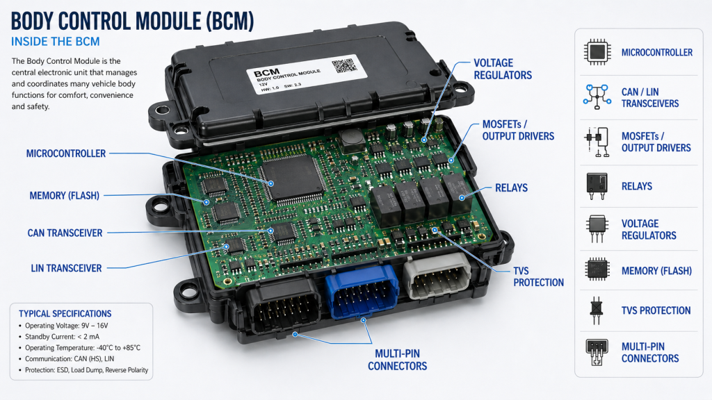
What Is Inside a Body Control Module PCB?
A BCM PCB combines input circuits, processing, communication, regulated power, and output stages. The PCB carries both sensitive logic signals and currents used to operate external loads.
Power entry and regulation
The input section conditions vehicle power and supplies the internal voltage rails. Protection and regulation must suit the platform’s expected operating range and disturbances.
Depending on the design, this section may include reverse-polarity protection, transient suppression, filtering, switching regulators, and linear regulators.
Microcontroller and memory
The microcontroller processes input states, executes control logic, communicates with other modules, and manages diagnostics. Memory stores firmware, configuration, and selected operating information.
Reset supervision and watchdog functions help define behavior during abnormal operating conditions.
Input interfaces
Switch inputs may need filtering, pull-up or pull-down arrangements, protection, and diagnostic capability. Their design must account for harness exposure and the electrical characteristics of the connected device.
Communication interfaces
CAN and LIN transceivers connect digital processing to the physical vehicle network. Their placement, protection, supply decoupling, and return paths influence communication performance.
Output stages
Relays, high-side switches, low-side switches, and motor drivers control different load types. Current sensing and fault reporting can help distinguish normal startup behavior from overloads or wiring faults.
The component arrangement should follow the signal and current paths. Keeping related circuits physically coherent makes layout review, testing, and fault analysis easier.
What Causes BCM PCB Failures?
BCM board failures can result from electrical overstress, heat, moisture, contamination, mechanical loading, component defects, or assembly problems.
The surrounding system often contributes. A shorted actuator can overload an output stage, while a damaged enclosure seal can expose a previously sound board to moisture.
Electrical overstress can damage input protection, regulators, transceivers, or output devices. Investigation should identify the entry path and the operating event rather than stopping at the visibly damaged component.
Thermal stress can affect power devices and nearby connections. Review load current, simultaneous channel operation, enclosure temperature, and the available heat-transfer path.
Moisture and contamination can produce corrosion or leakage between conductors. Cleaning requirements, coating coverage, connector sealing, and enclosure design work together to control exposure.
Mechanical stress can affect connector solder joints, mounting areas, and unsupported board sections. Harness forces and enclosure tolerances deserve attention alongside vibration.
After identifying a failed part, determine whether it was the original cause or a consequence. Replacing an output switch without resolving an external short can reproduce the same failure.
For engineering teams, the most useful failure report connects the symptom, electrical measurements, physical findings, and corrective action to the affected design revision.
How Should a BCM PCB Be Designed for Reliable Operation?
Reliable BCM PCB design starts with the vehicle power environment, load list, communication interfaces, enclosure, and operating profile.
Specify these inputs before selecting copper thickness or board material. A laminate designation alone does not establish the electrical, thermal, or mechanical performance of the finished controller.
Protect the power and harness interfaces.
Position protection components so disturbance currents have short, controlled paths. Review component voltage ratings together with clamp behavior, pulse energy, parasitic inductance, and the protected device’s limits.
Place decoupling near the relevant supply pins and preserve appropriate return paths for the currents involved.
Calculate load-path resistance and heating.
For an illustrative copper path that is 50 mm long, 2 mm wide, and 35 µm thick, using copper resistivity of approximately 1.72 × 10⁻⁸ Ω·m at 20°C:
R = ρL ÷ A ≈ 0.0123 Ω
At 3 A, the calculated drop is approximately 37 mV, and conductor loss is approximately 0.11 W.
This calculation covers the idealized conductor. Vias, connectors, solder joints, temperature rise, and manufacturing tolerances contribute to the actual path.
Evaluate power devices at realistic temperatures.
As a component example, the TPS1H100-Q1 is specified as a 40 V, 100 mΩ single-channel smart high-side switch. Its data sheet illustrates why output-stage selection involves current limiting, sensing, thermal behavior, and fault handling as well as nominal resistance.
For any chosen driver, use the applicable resistance and operating limits at the expected temperature. A room-temperature typical value is insufficient for worst-case thermal assessment.
Keep switching currents away from sensitive references.
Arrange high-current loops, regulator switching nodes, and sensing returns deliberately. Ground-plane splits should follow a justified return-current strategy rather than an assumption that physical separation always reduces noise.
Design connectors and test access together.
Provide mechanical support for harness loads and accessible test points for required production measurements. Resolve fixture access before component placement becomes fixed.
A board that can be tested clearly is easier to release, diagnose, and reproduce.
What Testing Does a BCM PCB Assembly Need?
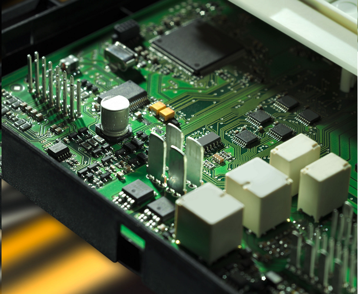
A BCM test plan should distinguish assembly verification, functional testing, and design qualification.
Assembly inspection checks the build. Functional testing checks specified behavior. Qualification evaluates whether the design and construction meet the agreed environmental and electrical requirements.
| Test Stage | Main Coverage | Parameters or Records | Scope to Define |
| Incoming verification | PCB construction and approved components | Board revision, BOM, material and lot records | Required documentation and sampling |
| AOI and visual inspection | Placement, polarity, accessible solder joints | Inspection criteria and defect records | Package visibility and inspection coverage |
| X-ray inspection | Selected hidden joints and internal solder features | Images and package-specific acceptance criteria | Components and features requiring examination |
| ICT or flying-probe testing | Accessible circuit connections and selected component checks | Resistance, capacitance, continuity, isolation | Test access and circuit limitations |
| Programming verification | Correct firmware and configuration | Software revision, verification result, unit identity | Programming method and recovery procedure |
| Functional testing | Inputs, outputs, supplies, and communications | Rail voltage, load current, response, fault flags | Fixture, loads, messages, and acceptance limits |
| Sleep and wake testing | State transitions and low-power behavior | Current versus time, wake source, response timing | Defined network and input conditions |
| Qualification testing | Specified electrical and environmental durability | Test profiles, functional status, final results | Customer-approved standards, severity, and sample plan |
A production functional test should exercise the required behavior under defined loads. An output that toggles with no connected load may behave differently when driving the intended actuator.
For a representative output channel, the test specification could define the command, load type, expected current range, response time, and diagnostic status. Any overload or fault-injection test needs a controlled method appropriate to the design and test stage.
Sleep testing also needs a repeatable sequence. Define ignition state, bus activity, input conditions, settling time, and the current-measurement method.
Environmental and transient qualification should follow the customer’s approved requirements. Passing an end-of-line functional test establishes a different level of evidence from passing a complete qualification program.
How Does Manufacturing Affect BCM Reliability?
Manufacturing translates the released design into a repeatable assembly. The important controls include component identity, PCB construction, solder deposition, placement, reflow, connector assembly, cleanliness, and inspection coverage.
Power packages and connectors deserve particular attention because their electrical and mechanical demands differ from those of small passive components.
A controlled stencil and reflow process helps achieve the intended joints. Hidden thermal connections should be reviewed using package-specific criteria and the product’s thermal requirements.
Firmware and configuration belong in the build record alongside the hardware revision. Two visually identical assemblies can behave differently if their software or configuration differs.
For repeat orders, define how approved substitutions, component changes, stencil revisions, and test-program updates are authorized. Keep the relationship between the physical unit and its inspection and test records clear.
At EBest Circuit, we can coordinate PCB fabrication, component sourcing, assembly, and project-defined inspection and testing within the quoted scope. For BCM projects, providing the load requirements and functional test inputs early helps us assess assembly access, fixture needs, and the evidence required before shipment.
FAQs About Body Control Modules
Can an engine-only OBD reader diagnose every BCM fault?
BCM diagnosis generally requires a tool with body-system coverage for the specific vehicle.
Are BCM and BCU always interchangeable terms?
Their meanings depend on the manufacturer’s terminology and electrical architecture, so confirm the module designation in the service documentation.
Does a module with matching connectors guarantee compatibility?
Compatibility also depends on the part number, hardware revision, software, configuration, and supported vehicle equipment.
Can an aftermarket accessory affect BCM behavior?
An accessory can affect body-system operation if it changes circuit loading, supply quality, network activity, or wake-up conditions.
Does conformal coating make a BCM waterproof?
Coating protects selected board surfaces, while water resistance depends on the complete enclosure, connector, sealing, and assembly design.
Can an automotive-qualified IC establish qualification of the complete BCM?
Component qualification supports part selection, while the assembled module still requires its own specified validation.
Does a higher-Tg PCB material automatically improve every BCM design?
Material selection should match the assembly process, operating environment, and reliability requirements rather than Tg alone.
How Can EBest Circuit Support Your BCM PCB Project?
At EBest Circuit, we support PCB fabrication, component sourcing, and assembly with inspection and testing defined around your released design. Our engineering review can address board construction, connector assembly, package accessibility, stencil requirements, programming inputs, and production-test preparation.
Send your Gerber or manufacturing files, stackup, BOM, assembly drawings, quantities, and test requirements to sales@bestpcbs.com. Include the connector pinout, load specifications, firmware, and communication requirements where applicable so we can review the manufacturing scope and prepare a practical quotation.
You may also like


Tags: Body Control Module, Body Control Module PCB, body control module symptoms