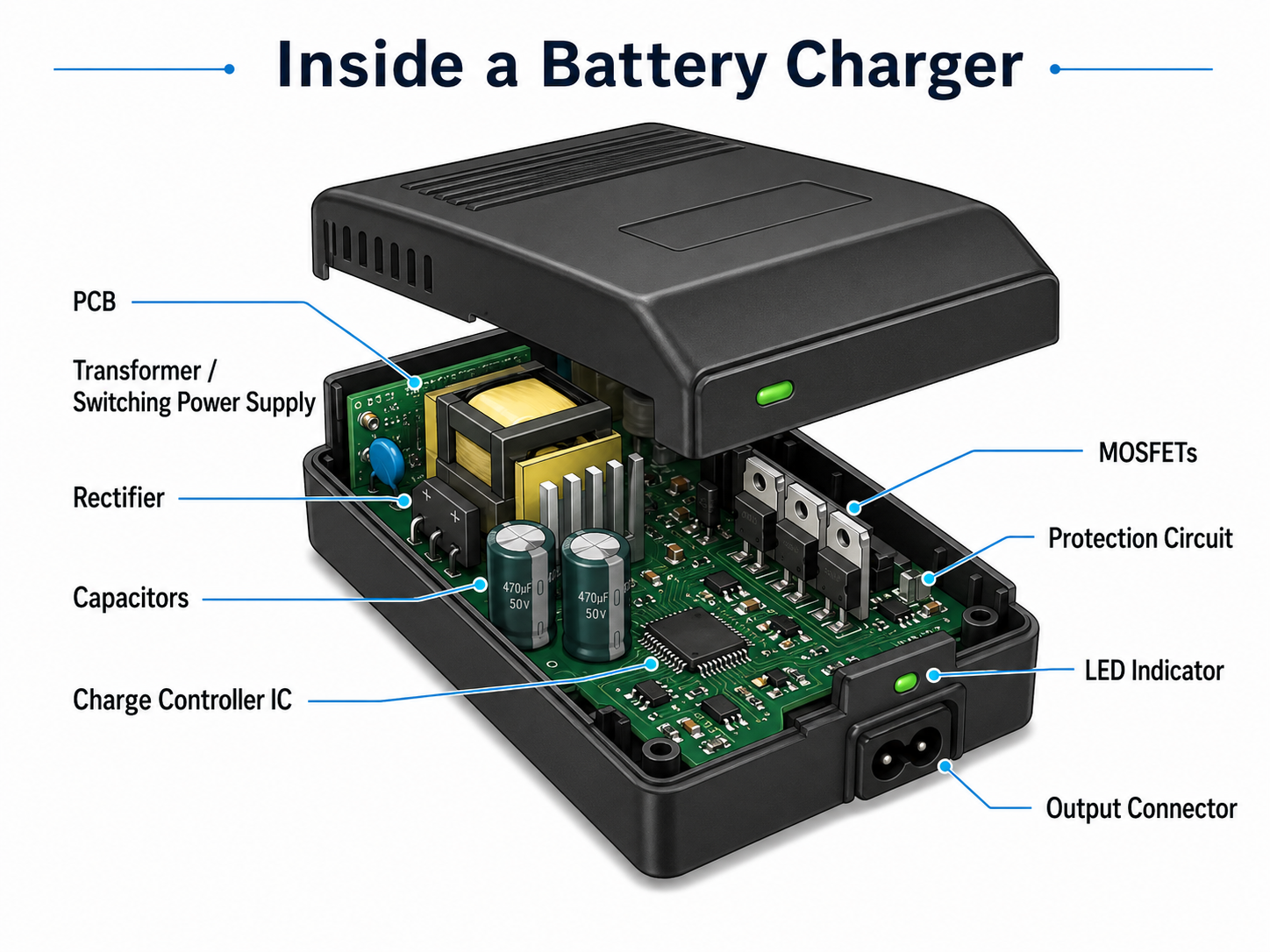
What is inside a battery charger? Inside a battery charger, there is usually a printed circuit board, power conversion circuit, rectifier, capacitors, resistors, MOSFETs, charge controller IC, protection components, LED indicators, connectors, and sometimes temperature sensors. These parts work together to convert input power into controlled DC power, then deliver the correct voltage and current to the battery.
A battery charger may look simple from the outside. It may only have a plastic case, a power plug, an output cable, and one or two indicator lights. But inside, it is a compact electronic system. It must manage voltage, current, heat, safety, and battery chemistry at the same time.
What Is Inside a Battery Charger?
Inside a battery charger, you will usually find electronic components that handle three main jobs: power conversion, charging control, and safety protection. The charger first receives input power, changes it into usable DC power, then regulates that output according to the battery type.
A simple charger may contain only a transformer, rectifier, capacitor, resistor, and output connector. A modern smart battery charger is more advanced. It may include a switching power supply, charger management IC, MOSFETs, current sensing circuit, temperature detection, reverse polarity protection, and status display.
In most modern chargers, the PCB acts as the foundation. It mechanically supports all components and electrically connects the full circuit. The copper traces on the PCB carry power and signals from one section to another. For low-power chargers, the board may be small and simple. For high-current battery chargers, the PCB must support wider copper traces, stronger heat dissipation, and safer spacing between high-voltage and low-voltage areas.
A typical battery charger contains:
| Internal Part | Basic Function | Simple Explanation |
|---|---|---|
| PCB | Connects all components | The main board inside the charger |
| Power conversion circuit | Adjusts input power | Changes AC or DC input into usable voltage |
| Rectifier | Converts AC to DC | Makes current flow in one direction |
| Capacitor | Smooths voltage | Reduces ripple and stabilizes output |
| Charge controller IC | Controls charging | Manages voltage, current, and charging stages |
| MOSFET | Switches power | Controls current flow efficiently |
| Resistor | Sets values and sensing points | Helps control current, feedback, and signals |
| Protection circuit | Improves safety | Helps prevent overcurrent, short circuit, and overheating |
| LED indicator | Shows status | Displays charging, full, or fault condition |
| Connector | Links charger and battery | Delivers controlled power to the battery |
The exact design depends on the charger type. A phone charger, power tool charger, lead-acid battery charger, lithium-ion charger, and EV-related charger may all look different inside. However, they share the same core idea: controlled power delivery.
What Are the Main Components Inside a Battery Charger?
The main components inside a battery charger include the PCB, transformer or switching power supply, rectifier, capacitors, controller IC, resistors, MOSFETs, diodes, protection devices, connectors, and indicators. Each part has a specific role in the charging process.
PCB
The PCB is the physical and electrical platform of the charger. All major components are soldered onto it. In a charger, the PCB must handle both power and control signals. That means the design needs good copper layout, proper spacing, and stable solder joints.
For higher-current designs, copper thickness and trace width become very important. If the copper path is too narrow, heat can build up. If spacing is too small between high-voltage and low-voltage areas, electrical safety may be affected.
Transformer or switching power supply
Older or simple chargers may use a transformer to step down AC voltage. Many modern chargers use switching power supply technology instead. A switching design is usually smaller, lighter, and more efficient.
In a charger, this stage prepares the input voltage before it is regulated for the battery. For example, a charger connected to wall AC power must reduce and convert the voltage before sending it to the battery.
Rectifier diodes or bridge rectifier
A battery requires DC power. If the charger receives AC input, the rectifier changes AC into pulsating DC. A bridge rectifier is common in many AC-powered charger designs.
The rectifier is one of the key parts in the power conversion path. Without it, AC power cannot be directly used for battery charging.
Capacitors
Capacitors help smooth voltage ripple. After rectification, the voltage is not perfectly stable. Capacitors store and release energy to make the DC output smoother.
In switching chargers, capacitors also support filtering, noise reduction, and transient response. Poor-quality or aging capacitors can cause unstable output, overheating, or abnormal charger behavior.
Charge controller IC
The charge controller IC manages the charging profile. It can control constant current, constant voltage, termination current, pre-charge, trickle charge, and protection functions depending on the battery type.
For lithium-ion and LiFePO4 chargers, this part is extremely important because these batteries require accurate voltage control.
MOSFETs
MOSFETs are semiconductor switches. They help control current flow with high efficiency. In smart chargers, MOSFETs may be used for power switching, reverse protection, battery connection control, or DC-DC conversion.
A good MOSFET selection affects efficiency, heat generation, and current handling.
Resistors and current sense components
Resistors are small but important. They may set feedback voltage, limit current, divide voltage, or measure charging current. In many charger circuits, a current sense resistor helps the controller know how much current is flowing to the battery.
Protection components
A charger may include fuses, TVS diodes, NTC thermistors, MOVs, zener diodes, and thermal sensors. These parts help protect against abnormal conditions such as surge, overcurrent, reverse polarity, and overheating.
LEDs or display
LED indicators show charging statu. A red light may mean charging. A green light may mean fully charged. Some smart chargers use displays to show voltage, current, battery percentage, or fault codes.
How Does a Battery Charger Work Step by Step?
A battery charger works by converting input power into a controlled DC output, then adjusting the voltage and current according to the battery’s charging requirement. The process may look simple, but it includes several important stages.
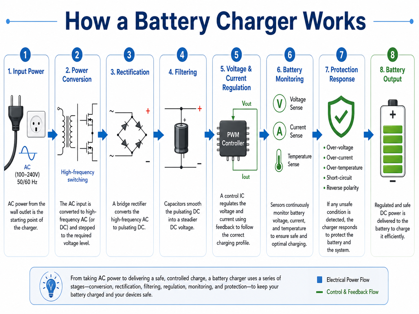
Step 1: Input power enters the charger
The charger receives power from an AC wall outlet, USB power adapter, solar panel, vehicle supply, or DC power source. The input type affects the internal circuit design.
An AC charger needs isolation, rectification, and voltage conversion. A DC-input charger may use a buck, boost, or buck-boost converter to adjust voltage.
Step 2: The input power is converted
If the charger uses AC input, the voltage must be stepped down and converted. In older linear chargers, this may be done with a transformer. In modern chargers, a switching power supply is more common.
Switching designs can achieve better efficiency and smaller size. That is why compact chargers today can deliver relatively high power from a small enclosure.
Step 3: AC is converted into DC
The rectifier stage changes AC into DC. Batteries store energy through chemical reactions, and they require direct current for charging. This is why rectification is essential in AC-powered chargers.
Step 4: The DC voltage is filtered
Capacitors smooth the rectified voltage. The goal is to reduce ripple and provide a more stable DC bus for the next control stage.
Stable voltage helps the charger IC or power regulation circuit work more accurately.
Step 5: Voltage and current are regulated
The charger does not simply send maximum power into the battery. It regulates current and voltage. For many lithium-based batteries, charging usually starts with a controlled current. When the battery reaches the target voltage, the charger holds the voltage and lets the current gradually decrease.
This method helps improve charging efficiency and battery life.
Step 6: The controller monitors the battery
A smart charger checks battery voltage, current, temperature, and sometimes battery presence. If the battery is too deeply discharged, the charger may start with a gentle pre-charge current. If the battery is too hot, the charger may reduce or stop charging.
Step 7: Protection circuits respond to faults
If there is a short circuit, reverse polarity, overvoltage, or excessive heat, the protection circuit helps limit damage. In advanced chargers, the controller IC may shut down the output until the fault is removed.
Step 8: The charger indicates charging status
The LED or display shows the charging state. Basic chargers may use simple red and green lights. Smart chargers may show fault codes, voltage, charging stage, or battery health information.
What Is the Role of the PCB Inside a Battery Charger?
The PCB inside a battery charger connects, supports, and organizes the full electronic circuit. From an engineering view, the PCB is not just a board. It directly affects current capacity, heat dissipation, safety spacing, EMI behavior, and product reliability.
A charger PCB usually has different functional areas. One side may handle high-voltage input. Another area may handle low-voltage output and control signals. In a well-designed PCB layout, these areas are separated carefully.
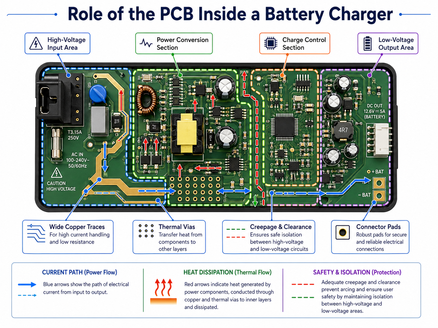
Power routing
Charging current flows through copper traces. If the current is high, the copper path must be wide enough. For a compact charger, this can be challenging because space is limited. Engineers may use wider traces, copper pours, thicker copper, or multiple layers to reduce resistance and heat.
Thermal performance
Power components such as MOSFETs, diodes, transformers, and regulators generate heat. PCB copper can help spread heat. Thermal vias, copper planes, and proper component placement can improve heat transfer.
Poor thermal design may cause hot spots, unstable performance, or shortened component life.
Creepage and clearance
For AC-powered chargers, electrical spacing is very important. Creepage means the shortest path along the surface of the board between two conductive parts. Clearance means the shortest air distance between conductive parts.
High-voltage and low-voltage sections need safe spacing. This is a critical design point in charger PCB manufacturing.
EMI control
Switching chargers can create electromagnetic noise. PCB layout affects how much noise is generated and how well it is controlled. Good layout uses short switching loops, proper grounding, input filtering, and careful placement of power components.
Mechanical support
The PCB must also withstand plugging, cable movement, vibration, and heat cycling. Connector pads, solder joints, and mounting points need enough mechanical strength.
For PCB manufacturers and PCBA suppliers, charger boards require a balance of electrical performance and manufacturing stability. DFM review, soldering quality, component placement, and testing all matter.
What Components Convert AC Power to DC Power in a Charger?
The components that convert AC power to DC power in a charger usually include a transformer or switching power stage, rectifier diodes, bridge rectifier, filter capacitors, and voltage regulation circuit. Together, they change wall power into controlled DC power suitable for charging.
A simple AC-to-DC charger may follow this path:
AC input → transformer → bridge rectifier → filter capacitor → regulator → battery output
A modern switching charger may follow a more advanced path:
AC input → fuse and EMI filter → rectifier → high-voltage DC bus → switching transformer → secondary rectifier → output filter → charge controller → battery output
What Is a Charge Controller IC Inside a Battery Charger?
A charge controller IC is the control center of a modern battery charger. It manages charging voltage, charging current, charging stages, battery detection, termination, and protection functions.
Without a proper charge controller, the charger may provide power but may not charge the battery correctly. This is especially important for lithium-ion and LiFePO4 batteries because they require precise voltage limits.
A typical charge controller IC may manage several stages:
| Charging Stage | What Happens | Why It Matters |
|---|---|---|
| Battery detection | Charger checks if a battery is connected | Prevents incorrect output behavior |
| Pre-charge | Low current charges a deeply discharged battery | Helps recover low-voltage cells gently |
| Constant current | Charger supplies a set current | Provides efficient main charging |
| Constant voltage | Charger holds target voltage | Prevents overvoltage near full charge |
| Termination | Charging stops or reduces when current drops | Helps avoid unnecessary stress |
| Maintenance mode | Charger maintains battery safely | Common in lead-acid or smart chargers |
| Fault protection | Charger responds to abnormal conditions | Improves safety and reliability |
For lithium-ion batteries, the constant current and constant voltage method is widely used. During the constant current stage, the charger supplies a controlled current. When the battery voltage reaches the target level, the charger switches to constant voltage. The current then gradually decreases.
The charge controller IC may also communicate with external components. It can read voltage feedback through resistor dividers, monitor current through a sense resistor, drive MOSFETs, and read temperature through an NTC thermistor.
In high-quality charger PCB design, the controller IC needs clean signal routing. Current sense traces should avoid noise. Feedback traces should be short and stable. Thermal-sensitive parts should be placed where they can measure meaningful temperature.
What Is the Difference Between a Basic Charger and a Smart Battery Charger?
A basic charger provides simple charging output, while a smart battery charger monitors the battery and adjusts the charging process. The main difference is control intelligence, safety response, and charging accuracy.
A basic charger may only use simple voltage regulation or current limiting. It can work for simple applications, but it may not detect battery condition precisely.
A smart charger usually includes a controller IC or microcontroller. It can detect battery voltage, charging current, temperature, battery status, and fault conditions. It may also support multiple charging stages.
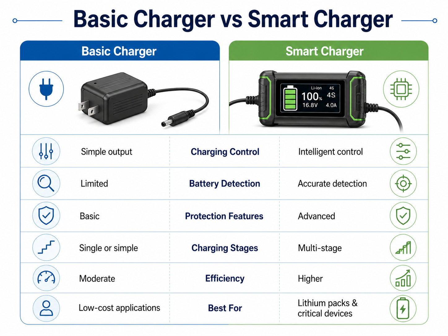
Smart chargers are especially useful when the battery is expensive, sensitive, or safety-critical. For example, power tool batteries, e-bike batteries, medical equipment batteries, and industrial backup batteries benefit from controlled charging.
Why Do Battery Chargers Need Protection Circuits?
Battery chargers need protection circuits because charging involves electrical energy, heat, chemical storage, and user interaction. Protection circuits help reduce risk during abnormal conditions such as overcurrent, overvoltage, overheating, short circuit, reverse polarity, and input surge.
A charger may be connected to different batteries, unstable power sources, or worn cables. Without protection, a small fault can damage the charger, battery, or connected device.
Common protection circuits include:
| Protection Type | Common Component | What It Helps Prevent |
|---|---|---|
| Overcurrent protection | Fuse, current sense resistor, controller IC | Excessive current flow |
| Overvoltage protection | TVS diode, zener diode, control IC | Output voltage spikes |
| Short-circuit protection | Fuse, MOSFET shutdown, controller protection | Damage from output short |
| Reverse polarity protection | Diode or MOSFET circuit | Damage from reversed battery connection |
| Thermal protection | NTC thermistor, thermal sensor | Excessive temperature |
| Input surge protection | MOV, TVS diode, fuse | Voltage surge from input side |
| Battery fault detection | Controller IC | Charging unsafe or damaged batteries |
Protection circuits are not only about component selection. PCB layout is also important. For example, a fuse should be placed close to the input path. High-current protection components need proper copper support. Thermal sensors should be placed near the part or battery area they are meant to monitor.
In charger PCB design, safety also depends on insulation distance. High-voltage input areas should be clearly separated from low-voltage output and user-accessible areas. Slots, spacing, and isolation barriers may be used in certain designs.
Protection design is one of the biggest differences between a low-cost charger and a reliable charger.
What Is the Difference Between Chargers for Lithium-Ion, Lead-Acid, NiMH, and LiFePO4 Batteries?
Different battery chargers use different charging methods because battery chemistries have different voltage limits, current behavior, temperature sensitivity, and full-charge detection methods. A charger for one battery type should not be casually used for another battery type.
A lithium-ion charger, lead-acid charger, NiMH charger, and LiFePO4 charger may all contain similar internal parts, but their control logic and voltage settings are different.
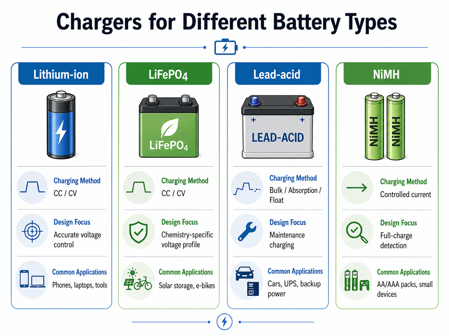
Lithium-ion chargers
Lithium-ion batteries require precise charging. A typical charger uses constant current first, then constant voltage. Overvoltage control is very important. That is why lithium-ion chargers often include a dedicated charger IC and temperature monitoring.
LiFePO4 chargers
LiFePO4 batteries are also charged with controlled current and voltage, but the voltage profile differs from standard lithium-ion chemistry. Using the wrong charger can lead to incomplete charging or battery stress.
Lead-acid chargers
Lead-acid batteries often use bulk, absorption, and float charging stages. Float charging helps maintain the battery after it is full. This is common in UPS systems, automotive batteries, and standby power applications.
NiMH chargers
NiMH batteries do not use the same voltage termination style as lithium-ion batteries. Many NiMH chargers detect full charge through voltage change, temperature rise, or timing logic.
What Usually Fails Inside a Battery Charger?
The parts that usually fail inside a battery charger include capacitors, fuses, MOSFETs, diodes, connectors, switching ICs, resistors, and solder joints. Failure often comes from heat, aging, overload, poor-quality components, or mechanical stress.
A charger can fail in several ways. It may stop powering on. It may get unusually hot. It may blink but not charge. It may output unstable voltage. It may charge slowly or stop too early.
| Symptom | Possible Internal Cause | Engineering Explanation |
|---|---|---|
| No power light | Fuse, input circuit, switching IC failure | The input side may not be powering the circuit |
| Charger gets very hot | MOSFET, diode, transformer, or capacitor issue | Power loss may be turning into heat |
| Battery does not charge | Connector, controller IC, sense resistor, output circuit | Output may not reach the battery properly |
| LED blinks abnormally | Battery detection fault or protection mode | Charger may detect a fault condition |
| Buzzing noise | Transformer, inductor, or switching circuit vibration | Load condition or aging may cause audible noise |
| Output voltage unstable | Aging capacitor or feedback problem | Ripple or regulation may be poor |
| Cable works only at certain angle | Output cable or connector damage | Mechanical fatigue can break conductors |
Capacitors are common failure points because they age with heat. If a capacitor loses capacitance or develops high ESR, the charger output may become unstable.
Connectors and cables also fail often because they experience repeated movement. A good PCB design should provide strong connector pads, proper strain relief, and enough solder support.
How Does PCB Design Affect Battery Charger Safety and Reliability?
PCB design strongly affects battery charger safety and reliability because the board controls current paths, heat distribution, electrical spacing, noise behavior, and mechanical strength. A charger with good components can still perform poorly if the PCB layout is weak.
Copper thickness and trace width
Charging current must pass through copper traces. If the trace is too narrow, resistance increases and heat rises. For higher-current chargers, designers may use thicker copper, wider traces, copper pours, or multiple layers.
The required trace width depends on current, copper thickness, allowable temperature rise, and board structure.
Thermal layout
Heat-producing parts need enough copper area. MOSFETs, diodes, regulators, and transformers should not be crowded without thermal planning. Copper planes and thermal vias help move heat away from hot spots.
High-voltage and low-voltage separation
AC chargers must separate the primary and secondary sides. Proper creepage and clearance distances help improve electrical safety. In some cases, isolation slots are added to increase surface distance.
Grounding and noise control
Switching power circuits create fast current changes. Poor layout can increase EMI and output noise. Engineers reduce this by keeping high-current loops short, separating noisy nodes, and using proper grounding.
Component placement
The input protection components should be near the input. The output capacitor should be close to the output stage. Feedback components should be near the controller IC. Temperature sensors should be placed near the heat source or battery contact point they monitor.
Soldering and assembly quality
Battery charger PCBs often include power components, through-hole connectors, and sometimes heavy parts. Strong solder joints matter. AOI, functional testing, and proper process control improve consistency.
How to Choose a Reliable Battery Charger PCB Manufacturer?
To choose a reliable battery charger PCB manufacturer, look for a supplier that understands power electronics, safety spacing, copper design, thermal management, PCBA assembly, and functional testing. A charger PCB is not just a standard circuit board. It is part of a power delivery system.
A good manufacturer should be able to review your design before production. DFM feedback can help identify risks such as narrow high-current traces, insufficient copper area, poor spacing, weak connector pads, and difficult assembly points.
When selecting a battery charger PCB supplier, consider these points:
| Selection Factor | Why It Matters for Charger PCB |
|---|---|
| Power PCB experience | Charger boards handle current, heat, and conversion circuits |
| DFM review | Helps reduce layout and production risks before fabrication |
| Copper capability | Supports high-current paths and thermal performance |
| Surface finish options | Affects solderability and long-term connection quality |
| PCBA service | Supports complete charger board assembly |
| Component sourcing | Helps control BOM quality and lead time |
| Testing ability | Functional tests verify charging output and protection behavior |
| Quality system | Improves production consistency and traceability |
| Engineering support | Helps optimize design for manufacturability and reliability |
For charger PCB projects, it is better to work with a manufacturer that can support both PCB fabrication and PCB assembly. This reduces communication gaps between bare board production, component sourcing, SMT assembly, through-hole soldering, and final testing.
If the charger is used in medical, industrial, automotive, energy storage, or outdoor equipment, reliability requirements are higher. The PCB manufacturer should understand application conditions, such as heat, vibration, humidity, current load, and long service life.
A capable PCB partner can help review:
- Copper thickness and trace width
- Creepage and clearance distance
- Thermal pad design
- Solder mask opening
- Connector reinforcement
- SMT and through-hole assembly process
- AOI and functional test requirements
- Box-build or cable assembly needs
For battery charger PCB manufacturing, engineering support is valuable. EBest PCB is an experienced PCB and PCBA manufacturer with over 20 years of PCB manufacturing experience. We have produced charger PCBs for customers across different applications, including vehicle chargers, battery charging modules, industrial power chargers, and custom charging control boards.
With strong engineering support, PCB fabrication capability, component sourcing, and PCBA assembly services, EBest PCB helps customers turn charger PCB designs into reliable finished products.
FAQs About What Is Inside a Battery Charger
1. What components are inside a battery charger?
A battery charger usually contains a PCB, rectifier, capacitors, resistors, MOSFETs, controller IC, protection components, connectors, and LED indicators. If the charger uses AC input, it may also include a transformer or switching power supply stage.
2. Is there always a PCB inside a battery charger?
Most modern battery chargers have a PCB inside. The PCB connects the power conversion circuit, control circuit, protection circuit, and output connector. Very simple old chargers may have fewer parts, but modern chargers almost always use a circuit board.
3. What does the capacitor do inside a battery charger?
A capacitor smooths voltage and reduces ripple. After AC is converted to DC, the voltage may still fluctuate. The capacitor helps stabilize the output so the charger can provide cleaner power to the battery.
4. What does the rectifier do in a battery charger?
The rectifier converts AC power into DC power. Batteries need DC charging current, so rectification is necessary when the charger receives AC input from a wall outlet.
5. What is the most important part inside a smart battery charger?
The charge controller IC is one of the most important parts. It manages the charging process, controls voltage and current, checks battery condition, and helps trigger protection functions when needed.
6. Why does a battery charger need a protection circuit?
A protection circuit helps respond to abnormal conditions such as overcurrent, overvoltage, overheating, short circuit, and reverse polarity. It improves safety and helps protect both the charger and the battery.
7. Can I use one charger for different battery types?
You should only use a charger that matches the battery chemistry, voltage, and current rating. Lithium-ion, LiFePO4, lead-acid, and NiMH batteries have different charging requirements.
8. Why does my battery charger get hot?
A charger gets warm because power conversion creates heat. Mild warmth can be normal, especially during fast charging. Excessive heat may indicate overload, poor ventilation, aging components, or weak thermal design.
Conclusion
For simple consumer chargers, compact design and cost are often major considerations. For industrial, medical, automotive, energy storage, and power tool chargers, reliability and safety become much more important. A well-designed charger PCB helps the whole charging system work more safely and consistently.
If you are developing a battery charger PCB or need professional PCB assembly support, choosing an experienced PCB manufacturer can help reduce design risk, improve production stability, and support better charging performance from prototype to mass production.