FPGA board design forms the foundation of modern electronic systems, enabling rapid prototyping and reliable production across industries from telecommunications to artificial intelligence. This comprehensive guide explores the essential principles, processes, and considerations for creating high-performance FPGA boards that balance development speed with manufacturing reliability.
Are you struggling with FPGA projects that face repeated revisions, signal integrity issues, or manufacturing delays?
- Extended development cycles due to incomplete initial specifications
- Signal integrity problems affecting system stability
- Power distribution issues leading to unpredictable performance
- Manufacturing complexities causing production delays
- Thermal management shortcomings reducing product lifespan
The corresponding viable solutions are as follows:
- Streamlined design processes with clear milestone planning
- Advanced simulation tools to preempt signal integrity issues
- Comprehensive power analysis during schematic phase
- DFM-focused layout approaches for smoother manufacturing
- Thermal optimization strategies integrated throughout design
EBest Circuit (Best Technology) specializes in high-quality PCB manufacturing with particular expertise in complex FPGA board design, prototype, fabrication, and PCBA. Our team combines engineering excellence with manufacturing precision to deliver reliable solutions for demanding applications. Pls feel free to contact us at sales@bestpcbs.com to discuss your specific custom FPGA board project requirements.
What Is FPGA Board Design?
FPGA (Field-Programmable Gate Array) board design encompasses the complete process of creating printed circuit boards that effectively integrate Field Programmable Gate Arrays with supporting components, interfaces, and power systems. This specialized discipline requires balancing electrical performance, thermal management, signal integrity, and manufacturability considerations.
Unlike standard PCB design, FPGA hardware design demands particular attention to high-speed signal routing, precise power sequencing, and thermal characteristics.
A successful FPGA board design must accommodate the programmable nature of FPGAs while providing a stable hardware platform that enables the full potential of the semiconductor device. This foundation supports everything from rapid prototyping to high-volume production when executed properly.
What Does an FPGA Board Schematic Include?
The schematic serves as the blueprint for your FPGA board, defining all electrical connections and component relationships. A comprehensive FPGA board schematic contains several critical sections that work together to create a functional system.
Key Schematic Sections:
- FPGA Component Symbol and Pin Assignments
- Complete representation of the FPGA device with all user I/O banks
- Proper grouping of power, ground, configuration, and user I/O pins
- Clear designation of bank voltages and special function pins
- Power Delivery Network (PDN)
- Voltage regulators for core voltage, auxiliary voltage, and bank voltages
- Power sequencing circuitry meeting FPGA manufacturer specifications
- Decoupling capacitor networks tailored to frequency requirements
- Clock Distribution Circuitry
- Primary clock sources (crystals, oscillators) with appropriate loading
- Clock distribution chips for multiple clock domains
- Termination schemes matching clock signal requirements
- Configuration Circuitry
- JTAG interface for programming and debugging
- Non-volatile memory for storing FPGA bitstream (Flash, PROM)
- Configuration mode selection circuitry
- Interface and Connectivity
- High-speed serial interfaces (PCIe, SATA, Ethernet)
- Memory interfaces (DDR3/4, QDR, RLDRAM)
- General-purpose I/O connections and expansion headers
A well-structured schematic forms the foundation for successful FPGA PCB design, ensuring that all electrical requirements are properly documented before layout begins.
Step-by-Step FPGA Hardware Design Process
The FPGA hardware design guide process follows a structured approach from concept to production. This methodology ensures that potential issues are identified and addressed early, reducing development time and minimizing revisions.
Phase 1: Requirements Analysis and Component Selection
- Define System Specifications and Performance Targets: Clearly outline high-speed signal standards (e.g., 3.125 Gbps) and key timing parameters. A critical factor is signal rise time; for instance, a transistor-transistor logic (TTL) signal with a 600-ps rise time is considered high-speed. The system bandwidth requirement is determined by the target data rate and expected edge speed.
- Select Appropriate FPGA Family and Package: Consider the package’s impact on signal integrity. Flip-chip packages typically offer lower inductance compared to traditional packages, which is beneficial for mitigating Simultaneous Switching Noise (SSN).
- Choose Supporting Components (Memories, Interfaces, Power Systems): When selecting connectors, rigorously evaluate the parasitic discontinuities they introduce. For example, an SMA connector with 2.9 pF of capacitive discontinuity can degrade a 3.125 Gbps signal, resulting in a 50 mV reduction in eye opening and a 16 ps increase in peak-to-peak jitter compared to a lower-capacitance (1.2 pF) alternative. Component choices must minimize inductive and capacitive loading.
Phase 2: Schematic Design and Capture
- Develop Hierarchical FPGA Board Schematic with Clear Functional Blocks.
- Perform Initial Signal Integrity and Power Integrity Analysis.
- Create Comprehensive Design Rules Based on FPGA Manufacturer Guidelines: Design rules must include a clear termination strategy. A termination decision is based on the relationship between signal rise time and transmission line length. For a signal with a 300 ps rise time on FR4 material (~180 ps/inch delay), if the trace length exceeds wavelength/10 (~1.1 inches), termination is mandatory to prevent signal reflections.
- Review Schematic with Cross-Functional Team Including Firmware Engineers.
Phase 3: PCB Layout Implementation
This phase is critical for design success and requires meticulous attention to high-speed layout principles.
- Component Placement Optimized for Signal Flow and Thermal Management.
- Implementation of FPGA Board Layout Following High-Speed Design Principles:
- Differential Pair Routing: Differential pairs should be routed in a tightly coupled fashion. Trace spacing should adhere to the ”3W” rule (edge-to-edge separation of at least three times the trace width) to prevent crosstalk. Simulations confirm that maintaining this spacing suppresses crosstalk to microvolt levels.
- Minimizing Discontinuities:
- Vias: Avoid vias wherever possible. When essential, ensure symmetrical via configuration for differential pairs to convert discontinuity into common-mode noise. A via on a 93-mil thick board introduces approximately 0.7 pF of capacitive discontinuity; this impact is more severe on thicker boards.
- Bends: Avoid 90-degree right-angle bends. Use mitred 45-degree bends or arcs, as 90-degree bends increase capacitance, causing signal ringing and delay.
- Return Path Integrity: High-speed signals (200 MHz and above) must reference a solid ground plane instead of a power plane for a cleaner reference. At layer change points, abundant ground vias must be provided adjacent to signal vias to ensure return currents have a low-inductance path. A longer return path increases loop inductance.
- Stackup Design with Appropriate Layer Count and Impedance Control: Stripline configurations offer superior radiation immunity compared to microstrip. A fundamental rule is to place power and ground planes as close together as possible. Reducing the plane separation from 17 mils to 4 mils significantly increases inter-plane capacitance, reducing power plane peak-to-peak noise from 70 mV to below 50 mV and providing effective decoupling over a wide frequency range.
- Power Distribution Network (PDN) Layout with Proper Plane Segmentation.
Phase 4: Design Verification and Simulation
- Signal Integrity Simulation for Critical High-Speed Interfaces: Use Time-Domain Reflectometry (TDR) simulations to identify impedance discontinuities from vias and connectors. Employ eye diagram analysis to evaluate the overall health of high-speed links (e.g., 3.125 Gbps), quantifying jitter and eye opening.
- Power Integrity Analysis to Verify Voltage Regulation and Decoupling.
- Thermal Analysis to Ensure Adequate Cooling Solutions.
- Design Rule Checking (DRC) and Electrical Rule Checking (ERC).
Phase 5: Prototyping and Testing
- Board Fabrication and Assembly.
- Power-On Testing and Validation of All Power Rails.
- FPGA Configuration and Basic Functionality Testing.
- Comprehensive System Testing Under Various Operating Conditions: Testing must include Simultaneous Switching Noise (SSN) analysis. Configuring non-critical I/O pins as programmable ground or power pins in the vicinity of switching I/Os effectively reduces ground bounce. Furthermore, using slower slew-rate drivers where the design permits is a practical method to minimize SSN, as ground bounce is proportional to L*di/dt.
Phase 6: Design Finalization for Production
- Incorporate Changes Identified During Prototyping.
- Finalize Design for Manufacturing (DFM) and Test (DFT).
- Prepare Complete Manufacturing Package.
- Transition to Production with Ongoing Support and Lifecycle Management.
This structured FPGA hardware design process, grounded in specific high-speed principles and quantitative analysis, ensures potential signal and power integrity issues are identified and mitigated early, significantly reducing the risk of costly revisions and accelerating time to market.
What to Consider in FPGA Board Layout and Signal Routing?
FPGA board layout presents unique challenges due to the high pin counts, multiple voltage domains, and high-speed signals characteristic of modern FPGAs. Proper implementation requires careful attention to several critical areas.
Critical Layout Considerations:
- Component Placement Strategy
- Position FPGA to minimize length of critical signals
- Group related components (memories, interfaces) near associated FPGA banks
- Consider thermal requirements when placing high-power components
- Ensure adequate space for decoupling capacitors near power pins
- Power Distribution System
- Implement split power planes for different voltage domains
- Use appropriate plane thickness based on current requirements
- Place decoupling capacitors in optimal locations relative to FPGA pins
- Minimize loop inductance in high-current paths
- High-Speed Signal Routing
- Match lengths for differential pairs and bus signals
- Maintain consistent impedance throughout signal path
- Minimize vias on critical signals to reduce discontinuities
- Implement proper termination strategies as identified in simulations
- Clock Distribution
- Route clock signals with minimum stubs and crossings
- Provide clean reference planes for clock signals
- Implement guard traces or ground shielding for sensitive clocks
- Follow FPGA manufacturer recommendations for clock routing
- Signal Integrity Preservation
- Control crosstalk through adequate spacing and ground shielding
- Minimize signal return path discontinuities
- Implement proper via transitions with accompanying return vias
- Use simulation results to guide layout decisions
Successful FPGA PCB design requires balancing these often-competing requirements to achieve optimal performance while maintaining manufacturability.
Custom FPGA Board Design for Your Application
Custom FPGA board design enables optimal solutions for specific application requirements across diverse industries. Different applications demand specialized approaches to FPGA implementation.
Communications Infrastructure
- High-speed serial links (25G+ Ethernet, OTN, CPRI)
- Precision timing with synchronization protocols (IEEE 1588)
- Robust power systems with backup capabilities
- Extended temperature operation for outdoor installations
Automotive Systems
- Compliance with automotive environmental standards
- Functional safety considerations (ISO 26262)
- Robust EMC/EMI performance for harsh environments
- Long-term component availability and reliability
Artificial Intelligence and Edge Computing
- High-bandwidth memory interfaces (HBM, GDDR6)
- Efficient thermal management for sustained computation
- Flexible expansion capabilities for co-processing
- Power-optimized designs for energy-constrained environments
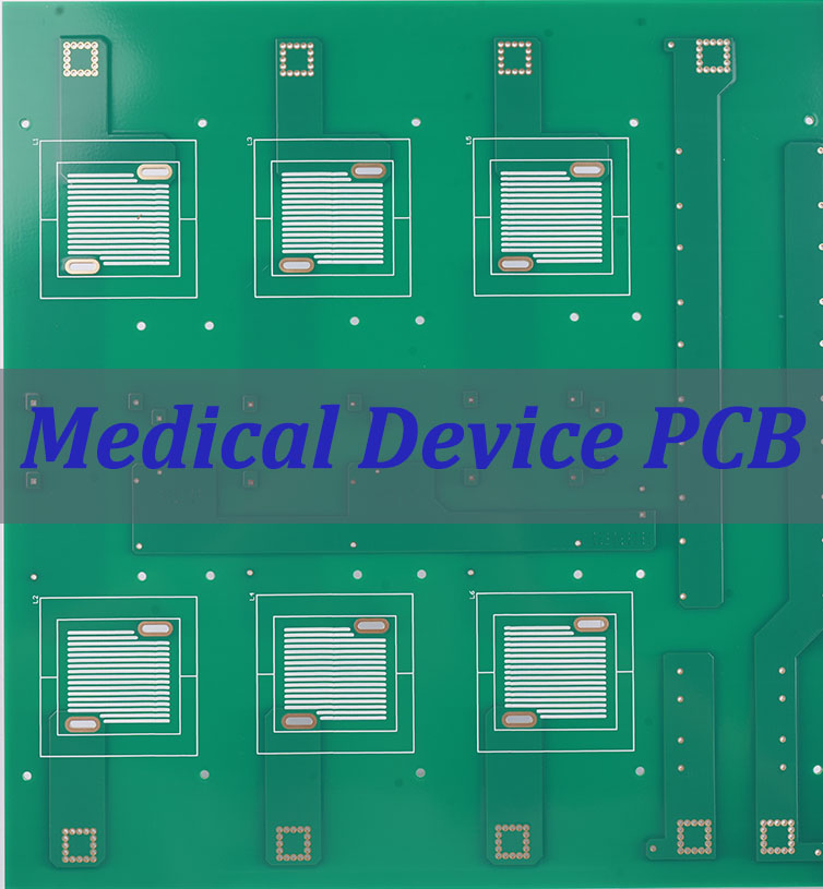
Medical Devices
- Signal integrity for high-precision data acquisition
- Compliance with medical safety standards (IEC 60601)
- Reliability and fail-safe operation requirements
- Miniaturization for portable and implantable devices
The right FPGA board design software selection plays a crucial role in implementing these specialized requirements. At EBest Circuit (Best Technology), we utilize industry-standard tools alongside proprietary methodologies to deliver optimized solutions for each application domain.
Why Choose EBest Circuit (Best Technology) for Your FPGA PCB Design & Manufacturing?
EBest Circuit (Best Technology) brings specialized expertise to FPGA PCB design and manufacturing, combining engineering excellence with manufacturing precision. Our approach ensures that your FPGA-based products achieve optimal performance while maintaining reliability throughout their lifecycle.
1. Proven Expertise
Founded in 2006, we have served over 1,700 satisfied clients across 40 countries. Our commitment is backed by international quality certifications, including ISO9001:2015, IATF16949, and ISO13485:2016, ensuring our processes meet the highest standards.
- Direct Engineering Collaboration: You get one-on-one expert support from our engineering-sales team, ensuring clear communication and personalized solutions from the very first step.
- Design for Excellence (DFM): We engage early in the design phase, providing valuable feedback to optimize your board for manufacturability, reliability, and cost-effectiveness, preventing costly revisions later.
2. Advanced Technical Capabilities for High-End FPGA Designs
Your complex FPGA designs require a manufacturer with sophisticated capabilities. Our state-of-the-art facilities and technical know-how are up to the task.
- High-Layer Count & HDI Expertise: We expertly manufacture complex multi-layer boards, supporting up to 32 layers (as per our capability chart), including HDI and impedance-controlled boards essential for high-speed FPGA applications.
- Superior Signal Integrity: We manage high-speed signals (25Gbps+) with precision, utilizing advanced materials like Rogers, Taconic, and Isola for high-frequency applications to minimize loss and crosstalk.
- Robust Power & Thermal Management: We have extensive experience in creating sophisticated power delivery networks for multi-voltage FPGAs and solving thermal challenges using Metal Core PCBs (MCPCBs) and Ceramic PCBs, ensuring your design remains stable and cool under load.
3. Manufacturing Precision & Rigorous Quality Control
Quality is non-negotiable. We implement strict quality control procedures at every stage, from raw material sourcing to final product testing. Our 97% on-time delivery rate proves our reliability.
- Tight Tolerance Manufacturing: As detailed in our PCB capability table, we achieve fine line widths/spacing down to 3/3 mil and controlled impedance tolerances of ±1mil, ensuring the accuracy your FPGA design demands.
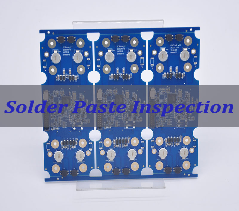
- Comprehensive Testing Regime: We employ a full suite of tests, including flying probe, boundary scan, and functional testing, to guarantee every board performs as expected.
- Supply Chain Integrity: We manage component sourcing to ensure authenticity and availability, mitigating project risks.
4. Seamless Full Turnkey Solution: From Prototype to Volume Production
Simplify your supply chain and accelerate time-to-market with our complete one-stop service. We handle everything under one roof.
- Rapid Prototyping: We value speed in innovation. We offer fast-turn PCB prototype services, with urgent orders shipped within 24 hours, allowing you to test and iterate quickly.
- Smooth Ramp-Up to Mass Production: With a monthly capacity of 260,000 square feet, we seamlessly scale from prototype to high-volume production without compromising quality or lead times.
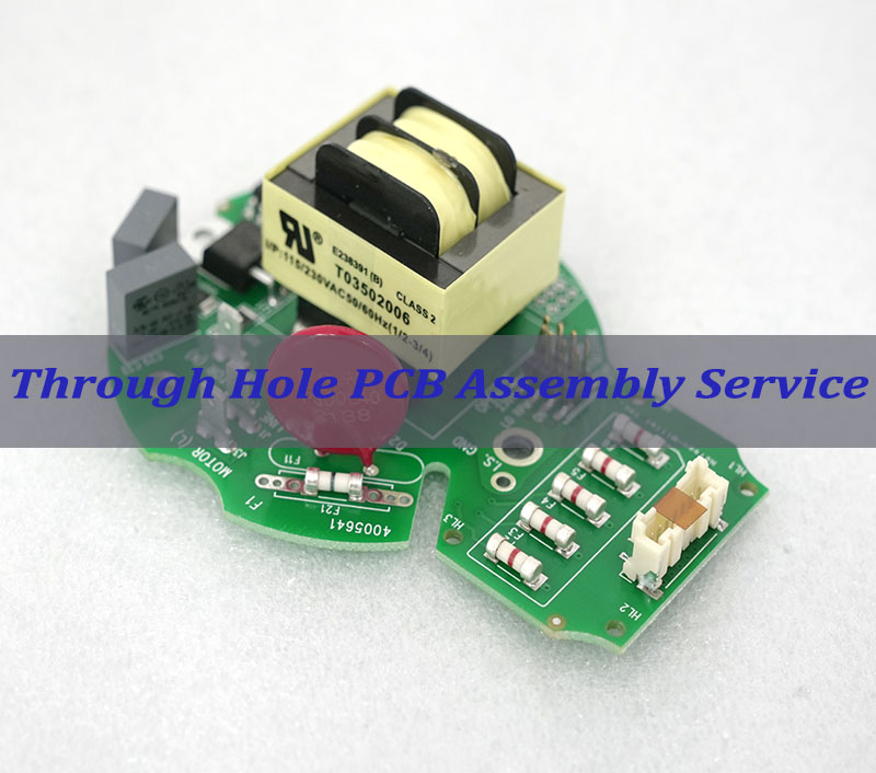
- End-to-End Support: Our services encompass PCB design, component sourcing, PCB assembly (SMT), and full box-build integration, providing a single point of accountability.
With EBest Circuit (Best Technology), your FPGA PCB projects benefit from precise high-speed design, multi-layer manufacturing expertise, and thorough validation at every stage. We integrate engineering insight with practical manufacturing solutions, ensuring boards that meet demanding performance, reliability, and thermal requirements—backed by transparent collaboration from prototype to production.
Case of FPGA Board Fabrication by EBest Circuit (Best Technology)
High-Speed Computing & Data Processing Board
This 6-layer FR4 PCB was designed for a high-performance computing application, such as a data acquisition system or a network processing card. The FPGA on this board handles high-speed data streams from multiple sources. The critical requirement was to maintain signal integrity for high-speed differential pairs (e.g., GTX transceivers) and ensure stable power delivery to the FPGA core. The red solder mask aids visual inspection during prototyping and assembly. This board is ideal for applications requiring robust signal performance in controlled environments, including industrial automation controllers and medical diagnostic equipment.
Key Parameters:
- Layer Count & Material: 6 Layers, FR4 High Tg 170
- Board Thickness: 1.6mm ±10%
- Copper Weight: Inner Layers: 0.5 oz; Outer Layers: 1 oz
- Surface Finish: ENIG (Gold: 1u”)
- Solder Mask & Silkscreen: Red LPI, White Legend
- Impedance Control:
- 50 ohms ±10% single-ended on Layers 1, 3, 4
- 100 ohms ±10% differential on Layers 1, 3, 4, 6
- Quality & Testing:
- 100% Electrical Test (Flying Probe) with report provided
- Impedance Test Report provided
- Compliance: IPC-A-600 Class 2 Standard, RoHS
Compact, High-Density Consumer/Communication Module
This 8-layer, 3-step HDI board is engineered for space-constrained, portable, or high-frequency applications like 5G communication modules, compact embedded vision systems, or advanced drone flight controllers. The use of HDI technology allows for a higher interconnection density in a thinner profile, which is crucial for miniaturization. The blind and buried vias optimize routing space, while the via-in-pad filled with conductive epoxy ensures a flat surface for precise BGA soldering of fine-pitch FPGAs and other components. This board exemplifies our ability to handle the most complex designs for the consumer electronics and telecommunications industries.
Key Parameters:
- Layer Count & Technology: 8 Layers, 3-step HDI (Blind/Buried Vias)
- Board Thickness: 1.191mm ±10%
- Copper Weight: 1 oz (Inner & Outer)
- Surface Finish: ENIG (Gold: 1u”)
- Solder Mask & Silkscreen: Green LPI, White Legend
- Critical HDI Process: Via-in-Pad (VIP) with Resin Plugging & Plating Over
- Impedance Control: 50 ohms ±10% target impedance for critical transmission lines
Both cases demonstrate core strengths of EBest Circuit (Best Technology):
- Impedance Control Expertise: Precise control over dielectric materials and line geometry to meet strict ±10% impedance tolerance, which is critical for FPGA signal integrity.
- Advanced Process Capability: Mastery of complex processes like HDI, resin-filled vias, and ENIG surface finish, ensuring reliability for fine-pitch components.
- Rigorous Quality Assurance: A commitment to quality is proven through mandatory electrical testing and detailed reporting, giving customers full confidence in the final product.
- Compliance with Standards: Adherence to IPC and RoHS standards guarantees the boards’ quality, consistency, and environmental safety.
By partnering with EBest Circuit (Best Technology), you gain access to a full turnkey solution that combines engineering insight with manufacturing precision, ensuring your innovative FPGA-based products are built to the highest standards of performance and reliability.
To sum up, FPGA board design represents a critical engineering discipline that bridges digital logic implementation with physical hardware realization. This guide has explored the essential elements of successful FPGA board development, from initial schematic creation through final manufacturing preparation.
By following a structured FPGA hardware design guide process and paying careful attention to layout considerations, engineering teams can create robust platforms that support both rapid prototyping and reliable production. The complexity of modern FPGAs demands specialized expertise in high-speed design, power delivery, and signal integrity to achieve optimal performance.
At EBest Circuit (Best Technology), our team is ready to partner with you on your next FPGA PCB project, providing guidance for DFM analysis, fast prototyping, reliable production, and SMT assembly. Pls feel free to contact our engineering team at sales@bestpcbs.com to discuss your specific FPGA board design requirements.
FAQs of FPGA Board Design
1. What is the architecture of the FPGA board?
The architecture of an FPGA board centers on a sophisticated multi-layer PCB stackup. This is not just a simple circuit board but a carefully engineered system where each layer plays a critical role:
- Signal Layers: These carry high-speed signals, often designed as striplines (sandwiched between reference planes) for better noise immunity.
- Power & Ground Planes: These provide stable power distribution. Keeping them close together creates natural capacitance for effective decoupling.
- Decoupling Capacitors: Placed near the FPGA’s power pins to filter high-frequency noise.
- Controlled Impedance Traces: Signal paths are designed with precise dimensions to maintain consistent impedance, minimizing reflections. Features like right-angle bends are avoided as they cause discontinuities.
2. What are the three types of FPGAs?
While the provided documents focus on design rather than cataloging types, FPGAs are commonly categorized by their core application focus:
- High-End / High-Performance FPGAs: Feature high-speed transceivers (e.g., for 3.125 Gbps signals), large logic capacity, and advanced memory interfaces for demanding applications like networking and data centers.
- Mid-Range / General-Purpose FPGAs: Balance cost, power, and performance for a wide array of applications, including industrial automation and video processing.
- Low-Cost / Low-Power FPGAs: Optimized for power-sensitive and cost-driven applications like consumer electronics and IoT devices.
3. Why is FPGA so hard?
The challenge lies in managing the analog effects in a digital world. As system speeds increase (e.g., signals with 70 ps rise times), the PCB design becomes critical and complex:
- Signal Integrity: High-speed signals are susceptible to reflections, crosstalk, and simultaneous switching noise (SSN), requiring careful termination and layout.
- Power Integrity: Delivering clean, stable power to the chip is difficult. Powerful transient currents can cause the power supply to “collapse” locally if not properly decoupled.
- Pin Assignment (Pin Swapping): Before routing, I/O pins often need to be reassigned to optimize signal paths. This is a complex process with strict rules (e.g., pins can only be swapped within the same voltage “bank”) that requires close collaboration with the system architect.
4. Can FPGA be used as GPU?
These are different tools for different jobs. The core difference is flexibility vs. raw throughput.
- FPGA as an Accelerator: An FPGA can be programmed to act as a custom hardware accelerator for specific algorithms. It offers high energy efficiency and extremely low latency because the algorithm is implemented in dedicated hardware circuits.
- GPU (Graphics Processing Unit): A GPU is a mass-produced, highly parallel processor optimized for processing large blocks of similar data (e.g., graphics pixels, AI model calculations). It excels at high computational throughput for parallelizable tasks.
5. Is A FPGA better than a GPU?
One is not universally “better” than the other.
- Use an FPGA when you need to create custom, efficient hardware for a specific, non-standard task, or when low latency is critical.
- Use a GPU for massive, highly parallel computational workloads like AI training or graphic rendering.
- They often work together in systems, with the FPGA handling specialized data preprocessing before sending it to the GPU.
6. What is a FPGA in simple terms?
Think of an FPGA as ”programmable hardware Lego.”
- It’s a chip filled with basic, unconnected building blocks (logic gates, memory cells).
- An engineer “programs” it using a Hardware Description Language (HDL) to connect these blocks, creating a custom digital circuit (like a processor or video decoder) directly in the hardware.
- Its biggest advantage is flexibility; the circuit’s function can be changed or updated even after the chip is on the circuit board.