

How to mount PCB accelerometer? Let’s discover benefits, applications, mount methods, common types, selection guide, cost for PCB accelerometer.
Are you troubled with these problems?
- Does accelerometer performance drift delay projects? Long rework cycles risk customer loss.
- How to balance low cost and high precision in accelerometer selection?
- Integration complexity slows production efficiency and yield, when will this improve?
As a PCB accelerometer supplier, EBest Circuit (Best Technology) can provide you service and solution:
- Integrated PCBA Design: 0.2mm precision placement + system-level packaging for one-time design success, boosting mass production yield by 20%.
- Smart Parameter Customization: Adjust range, frequency response, and temperature drift per scenario, 15% cost reduction with ±1% accuracy.
- 7-Day Rapid Delivery: 72-hour prototyping + 48-hour production ramp-up for faster delivery than client follow-ups.
Welcome to contact us if you have any request for PCB accelerometers: sales@bestpcbs.com.
Why Mount PCB Accelerometer?
Advantages of PCB Accelerometer:
- Measurement Precision & Reliability Double Guarantee: Employing high-rigidity mechanical design and precision sensing technology (e.g., ICP® piezoelectric sensors) ensures high data repeatability and minimal error, meeting stringent industrial testing requirements. Over 55% of aerospace testing systems adopt it as the preferred solution for critical parameter capture.
- Real-Time Guardian for Equipment Health Management: Permanent installation enables continuous vibration monitoring, instantly triggering fault alerts or emergency responses to significantly reduce unplanned downtime. For example, in bridge structural monitoring, it precisely assesses material fatigue states, providing scientific maintenance decisions and extending equipment life.
- Efficient Solution for Integrated Installation: Supports magnetic, adhesive, and stud mounting methods, adapting to metal/non-metal surfaces with compact sensor size. Wireless transmission reduces wiring complexity, enhancing field deployment efficiency, ideal for space-constrained precision equipment.
- Universal Sensor for Full-Scenario Coverage: From automotive crash testing (55% industry demand) to industrial predictive maintenance, its wide dynamic range and high-temperature resistance (e.g., high-temperature adhesive solutions) meet multi-industry harsh environment needs, serving as a cross-domain universal solution.
- Cost-Optimized Long-Term Economic Choice: With the piezoelectric accelerometer market expanding (CAGR 3.5%), technology maturity drives down procurement and maintenance costs. By reducing downtime losses and extending equipment life, clients achieve significant ROI improvements, forming a long-term economic benefit loop.
When Do You Need to Mount PCB Accelerometers?
Applications of PCB Accelerometer:
- High-Frequency Vibration Measurement: For measuring vibrations above 2-3 kHz, rigid mounting methods like stud mounting are mandatory to ensure accurate high-frequency signal transmission. Soft mounting (e.g., adhesive bonding) causes signal attenuation in high-frequency ranges.
- Permanent Monitoring Requirements: In long-term applications like Structural Health Monitoring (SHM), stud mounting is recommended to create a durable sensor-structure connection, preventing data distortion from loosening.
- Space & High-Reliability Applications: In aerospace/high-reliability sectors, accelerometers must be mounted on PCB areas with maximum deformation (per ECSS standards) to accurately measure vibration-induced acceleration and ensure product reliability.
- Harsh Environmental Conditions: Avoid wax-based adhesives in extreme temperatures/high-acceleration environments, use epoxy resins or stud mounting to prevent sensor detachment.
- Ultra-High Precision Needs: For extreme accuracy, mounting surfaces must be ultra-flat/smooth, with holes perpendicular to the surface. Surface irregularities or improper thread depth induce base strain, causing measurement errors.
- Rapid Installation/Removal: For multi-channel testing or system debugging, use specialized clips (e.g., Easy-mount Clips) or magnetic bases for quick sensor changes while balancing efficiency and accuracy.
- Temporary Testing/Surface Constraints: When surfaces can’t accommodate threaded holes (e.g., thin-walled structures), adhesive bonding or through-screwing provides a practical alternative installation method.
How to Mount PCB Accelerometer?
1. Stud Mounting Method (High-Frequency Vibration Priority)
- Operation Standard: Drill matching screw holes on the test structure and secure the accelerometer using M3-M6 stainless steel studs. Installation torque must strictly follow manufacturer specifications (e.g., PCB 352B01 model recommends 1.7N·m ±10%), controlled by a torque wrench.
- Data Support: Apply a 0.05mm-thick silicone grease layer (e.g., Dow Corning 111) between coupling surfaces to enhance frequency response above 2kHz by 30%, elevating resonant frequency from 4kHz to 8kHz (referencing U.S. PCB Company test data).
- Case: Volkswagen Germany employs this method for engine vibration monitoring, successfully capturing vibration signals within 20kHz with an error rate below 2%.
2. Adhesive Mounting Method (Temporary/Insulation Scenarios)
- Selection Criteria: For low-frequency tests (<1kHz), use cyanoacrylate (e.g., 502 adhesive); for high-temperature environments (-200°C~260°C), adopt high-temperature epoxy (e.g., 3M Scotch-Weld 2216); for permanent room-temperature installation, recommend dual-component epoxy.
- Points: Maintain adhesive layer thickness at 0.02-0.05mm, utilizing positioning fixtures for 24-hour curing. Seiko Epson Japan tests show a 0.03mm layer preserves 1.2kHz resonant frequency, a 40% improvement over a 0.1mm layer.
- Risk Control: Avoid adhesive contamination of mounting threads. U.S. PCB Company statistics indicate glue residue can cause high-frequency calibration errors up to 15dB.
3. Magnetic Mounting Method (Rapid Testing Solutions)
- Application Scenarios: Low-frequency measurements (<500Hz) on ferromagnetic surfaces, such as GE Renewable Energy wind turbine blade monitoring.
- Operation Norms: Use NdFeB magnetic bases (suction force >50N) with installation surfaces sandblasted to Ra0.8μm. B&K Canada tests reveal magnetic mounting reduces resonant frequency from 8kHz (stud mounting) to 2kHz.
- Safety Notes: Prohibited for >200g impact environments to prevent sensor damage from magnetic base slippage.
4. Specialized Scenario Solutions
- Triaxial Sensor Calibration: For X-axis measurements, employ inverted mounting by applying epoxy (e.g., Araldite 2012) at sensor corners to avoid center-cap vibrations. U.S. PCB 3713E1110G calibration data shows this reduces X-axis frequency response error from ±5% to ±1%.
- PCB Design Optimization: No metal vias within 2mm of LGA-package sensors. ADI U.S. tests indicate violation increases 1kHz noise by 3dB.
- Cable Management: Use silicone-sheathed cables (e.g., Belden 8723) with fixation spacing ≤100mm to prevent vibration coupling errors.
5. Quality Verification & Debugging
- Installation Validation: Utilize laser vibrometer comparison to verify mounting resonant frequency within 50-5000Hz, ensuring deviation <3% from factory calibration.
- Environmental Compensation: Recalibrate zero offset for every 10°C temperature change. National Instruments U.S. recommends automatic temperature compensation algorithms for -40°C~125°C environments.
- Removal Protocol: Soak in specialized solvent (e.g., 3M Novec 7100) for 30 minutes before removal to avoid mechanical damage ≥0.2mm from forceful extraction.
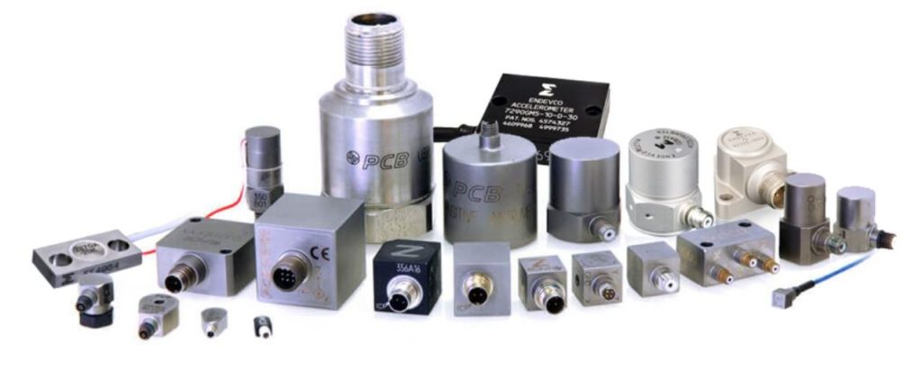
Common PCB Accelerometer Types
Piezoelectric Accelerometer
- Advantages: High sensitivity, wide frequency response, self-powering capability, robust temperature stability, low power consumption, excellent linearity.
- Applications: Aerospace vibration monitoring, weapon impact testing, industrial predictive maintenance, seismic detection, camera stabilization, automotive collision detection, structural health monitoring.
Capacitive Accelerometer
- Advantages: High precision, low power consumption, wide dynamic range, strong noise immunity, low temperature drift, simple structure, minimal drift.
- Applications: Consumer electronics (screen rotation/game controls), automotive ride comfort testing, aerospace equipment monitoring, medical motion detection, industrial level calibration, construction machinery attitude control.
Piezoresistive Accelerometer
- Advantages: High sensitivity, wide dynamic range, high-level output, low output impedance, overload protection, broad temperature tolerance, compact solid-state design.
- Applications: High-g shock scenarios (aerospace/weapon research), automotive crash testing, low-frequency vibration analysis, medical cardiac monitoring, equipment fault diagnosis, structural dynamic testing.
MEMS Accelerometer
- Advantages: Miniaturization, low power, high integration, wide bandwidth, low noise, vibration/shock resistance, rapid startup, portability compatibility.
- Applications: Smartphones (step counting/screen rotation), wearable activity tracking, game controller motion sensing, drone navigation, automotive airbag deployment, industrial predictive maintenance, aerospace IMUs.
Thermal Sensing Accelerometer
- Advantages: EMI resistance, low-frequency response, stable performance, low power, suitability for extreme environments (high temperature/explosion-proof).
- Applications: Low-frequency vibration monitoring (bridges/buildings), special environment tilt measurement, vehicle stability assessment (rollover detection), high-temperature industrial monitoring.
ICP/IEPE Accelerometer
- Advantages: Integrated amplifier, low-impedance output, strong noise immunity, high accuracy, wide temperature adaptability, user-friendly design, mainstream device compatibility.
- Applications: Industrial equipment vibration monitoring (motors/production lines), structural health monitoring (bridges/buildings), shock testing validation, petrochemical pipeline analysis, railway vibration assessment, environmental vibration tracking.
How to Choose the Right PCB Accelerometers?
1. Define Measurement Requirements and Environment
- Parameter Identification: Precisely define the physical quantities to be measured (e.g., low-level vibration, high-g shock, constant acceleration). Quantify the expected amplitude range (from ±5g for subtle motions to ±50,000g for extreme impacts) and the frequency spectrum of interest (DC for slow movements up to 50 kHz for very high-frequency phenomena).
- Environmental Conditioning: Document all operational environmental factors, including temperature extremes (standard: -18°C to +65°C; industrial: -55°C to +125°C), relative humidity levels, and the presence of corrosive chemicals, fuels, or intense electromagnetic fields.
- Spatial Constraints: Accurately measure the available mounting area and clearance. PCB accelerometers are available in various weights and sizes, from miniature 3g models for compact spaces to larger, more robust 100g+ units.
2. Select Core Performance Parameters
- Sensitivity Matching: Align sensitivity with signal strength. Low-level vibration applications require high sensitivity (>100 mV/g), while high-shock environments need lower sensitivity (<5 mV/g) to prevent signal clipping and ensure resolution across the full range.
- Frequency Response Verification: The sensor’s resonant frequency should be 3 to 5 times higher than the highest frequency component you need to measure. This prevents signal distortion and ensures accuracy by staying within the linear range of the accelerometer.
- Noise Floor Evaluation: Match the noise performance to your required resolution. Ultraprecision measurements demand micro-g (μg) resolution, whereas general industrial applications can use milli-g (mg) level sensors effectively.
- Transverse Sensitivity Specification: Select models with a low transverse sensitivity ratio, ideally less than 3%, to minimize measurement error from vibrations occurring perpendicular to the primary sensing axis.
3. Determine Electrical Characteristics and Output Type
- Output Signal Interface: Choose the appropriate output type. Voltage output is the simplest; 4-20 mA current loop is ideal for long-distance transmission with inherent noise immunity; and digital outputs (with IEPE being the most common integrated electronics type) simplify integration with data acquisition systems.
- Power Supply Requirements: Confirm the necessary excitation voltage. IEPE sensors typically require a constant current DC power supply (18-30 VDC) coupled with signal conditioning, whereas charge output types need an external charge amplifier.
- Output Impedance Considerations: Ensure electrical compatibility with your data acquisition system. Voltage output accelerometers must be connected to a high-impedance input (>1 MΩ) to avoid signal loading and degradation.
4. Evaluate Physical Construction and Mounting
- Housing Material Selection: Choose the material based on the environment: stainless steel for corrosive settings, titanium for the best strength-to-weight ratio in demanding applications, and aluminum for standard laboratory or industrial use.
- Mounting Methodology: Select a method that ensures a rigid mechanical connection. Stud mounting offers the highest fidelity, adhesive mounting provides convenience, and magnetic mounting is suitable for temporary diagnostic measurements.
- Connector Type: Use hermetic or military-specification connectors for harsh environments, coaxial connectors for laboratory benches, and ruggedized industrial connectors for production line testing.
- Integral Cable Choice: Specify low-noise cable for capturing very weak signals, fully shielded cable for areas with high electromagnetic interference (EMI), and flexible, durable cable for applications involving continuous movement.
5. Assess Environmental Ruggedness and Reliability
- Integrated Temperature Compensation: For applications with wide operating temperature swings, select units with built-in temperature compensation to maintain accuracy across the entire range.
- Environmental Sealing: Verify the Ingress Protection (IP) rating. IP67 is sufficient for most industrial environments, while IP68 is required for washdown, outdoor, or submerged applications.
- Base Strain Sensitivity: Optimize for models with low base strain sensitivity (e.g., <0.005 g/μɛ) to prevent false readings caused by strain on the mounting surface from distorting the sensor body.
- Electromagnetic Compatibility: Check for specifications regarding Radio Frequency Interference (RFI) and Electromagnetic Interference (EMI) rejection, which is critical when operating near motors, drives, or wireless equipment.
6. Match the Sensor to the Application Scenario
- Condition Monitoring: Prioritize long-term stability, low temperature drift, and a predicted operational lifespan exceeding 5 years for predictive maintenance systems.
- Shock and Impact Measurement: Select models with a high g-range (±500g to ±50,000g) and a very wide bandwidth to accurately capture short-duration, high-amplitude events without ringing.
- Laboratory Precision Testing: Focus on specifications like high resolution, very low noise floor, and triaxial synchronisation. Units supplied with individual calibration certificates are essential.
- Mobile/High-Reliability Applications: For automotive, aerospace, or defense uses, choose accelerometers rated for high shock survival, intense vibration, and extended temperature ranges, often to military standards.
7. Consider Economic Factors and Vendor Support
- Cost-to-Performance Balance: Avoid over-specifying. Systematically select the most cost-effective model that fully meets all technical and operational requirements.
- Calibration Services: Inquire about the calibration cycle (1 or 2 years is standard), associated costs, and the traceability of the calibration standards used.
- Technical and Application Support: Prefer vendors that provide comprehensive technical documentation, detailed application notes, and responsive expert support.
- Lead Time and Availability: Factor in project timelines by selecting models that are in stock or have short manufacturing lead times to prevent delays.
8. Execute a Practical Validation Process
- Prototype Testing: Never skip testing the shortlisted sensor models under real-world or simulated operating conditions to validate performance.
- Comparative Analysis: Create a decision matrix to objectively compare at least 2-3 candidate models based on their measured performance against your key criteria.
- Long-Term Stability Check: Conduct a continuous monitoring test for a minimum of 72 hours to identify any significant parameter drift or instability over time.
- Full System Integration Test: Verify that the accelerometer works seamlessly with the entire data acquisition chain, including cables, signal conditioners, and software.
How Much Does a PCB Accelerometer Cost?
The cost of PCB accelerometers varies greatly, depending on the specifications (range, accuracy, bandwidth, noise, output type) and the level of integration (bare chip, simple PCB module, module with conditioning circuitry). Roughly speaking: Basic MEMS chip (customer-installed PCB integration required): $1–$20+ (high-volume options can be as low as <$1, high-precision/specialized models >$20). Simple PCB module (chip soldered to a small board with basic connectors): $10–$50+.Standard IEPE/PCB module with signal conditioning: $30–$150+ (common for mainstream industrial applications, with mid-range performance). High-performance/low-noise/specialized environment PCB module: $100–$500+.
Why Choose EBest Circuit (Best Technology) as PCB Accelerometer Supplier?
Reasons why choose us as PCB accelerometer supplier:
- Quality Reliability, Precise Data: We employ high-precision laser cutting and micro-etching processes to ensure PCB trace tolerances ≤0.02mm. Combined with AOI automatic optical inspection and manual secondary verification, our dual-layer quality control achieves a first-pass yield of 98.6%. This guarantees zero drift and distortion in accelerometer signal acquisition, directly protecting your measurement accuracy.
- Stable Lead Times, Rapid Response: Powered by ERP intelligent production scheduling and a localized supply chain network, standard orders are delivered within 7-10 days. For urgent needs, we activate dedicated production lines within 48 hours, achieving over 95% on-time delivery accuracy. This mitigates project delays and ensures your production continuity.
- Transparent Pricing, Cost Control: Our tiered pricing model offers 5%-15% volume-based discounts. With Vendor-Managed Inventory (VMI) support, you gain real-time visibility into material costs, eliminating hidden fees. Long-term partners enjoy annual rebate policies, making budgeting predictable and cost-effective.
- Design Compatibility, Flexible Adaptation: Our PCBAs support multi-dimensional design compatibility with standard footprint libraries and custom pad design services. We accommodate 0201-0805 package devices and high-frequency substrates like Rogers and FR4, meeting diverse circuit design needs across applications.
- Mature Processes, High Yield Rates: With 12 years of PCB production expertise, we master core technologies including microvia blind/buried vias, HDI high-density interconnects, and impedance control. Statistical Process Control (SPC) ensures stable yields above 96%, reducing rework costs and accelerating your time-to-market.
- Environmental Compliance, Regulatory Safety: All products meet RoHS and REACH standards, utilizing lead-free soldering and water-soluble solder masks. This ensures compliance with EU and North American environmental regulations, avoiding import barriers or legal risks tied to non-conformance.
- Proactive Technical Support: We provide complimentary DFM (Design for Manufacturing) analysis during prototyping. This identifies design flaws, such as trace width/spacing violations or pad dimension errors early, preventing mass production risks and shortening your product launch timeline by over 30%.
Welcome to contact us if you have any inquiry for PCB Accelerometer: sales@bestpcbs.com.