

Why choose high dielectric PCB material? Let’s discover its definition, material list and properties, benefits, selection guide, cost and recommend material supplier through this blog.
Are you troubled with these problems?
- Is high-frequency signal instability plaguing your designs? Could PCB dielectric constant fluctuations be causing impedance mismatch?
- Struggling with cost containment? Has the price surge of high-Dk materials disrupted your inventory planning?
- Is sample testing taking too long? Can you receive small-batch verification materials within 72 hours?
As a high dielectric PCB material supplier, EBest Circuit (Best Technology) can provide you service and solutions:
- Precise Dk/Df parameter matching: Full Rogers/Taconic inventory with 24-hour parameter traceability to eliminate design validation discrepancies.
- Price volatility buffer: Long-term agreements lock in costs, with off-season stock support and peak-season priority allocation.
- Sample readiness: 72-hour rapid slicing and delivery with batch-specific COA reports to accelerate design iterations.
Welcome to contact us if you have any inquiry for high dielectric PCB materials: sales@bestpcbs.com.
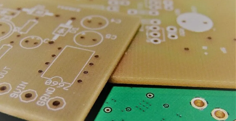
What is High Dielectric PCB Material?
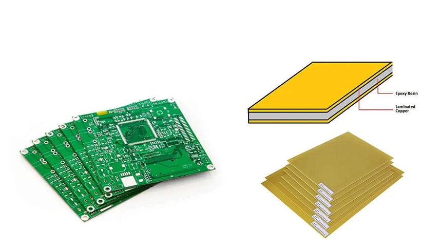
High Dielectric PCB Material (High Dk PCB) refers to specialized substrate materials engineered for high-frequency circuit applications (typically >1 GHz), characterized by two core attributes: high dielectric constant (Dk > 10) to enable compact signal transmission structures, and low dielectric loss (Df < 0.01) to minimize signal attenuation.
These materials are typically formulated using polytetrafluoroethylene (PTFE)-ceramic composites, hydrocarbon resins, or modified epoxy resins, with ceramic powders (such as barium titanate) incorporated to enhance dielectric performance. Such materials are particularly suitable for applications requiring miniaturization and high-frequency stability, including millimeter-wave radar systems and 5G base stations, where both compact design and signal integrity are critical.
High Dielectric Constant PCB Material List & Properties
| Material Model | Dielectric Constant (Dk) | Dielectric Loss (Df) | Thermal Conductivity [W/(m·K)] | Thermal Stability (°C) | Properties | Application |
| Rogers 4350B | 3.48±0.05 | 0.0037@10GHz | 0.69 | 280 | Low loss, excellent high-frequency stability, glass fiber reinforced | 5G base station antennas, mmWave radar |
| Taconic RF-35 | 3.5±0.05 | 0.0023@10GHz | 0.7 | 260 | Ultra-low loss, PTFE substrate, ideal for high-frequency transmission | Satellite communications, RF front-end modules |
| Isola I-SPEED | 3.3-3.5 | 0.0025@10GHz | 0.45 | 230 | Low-profile design, precise impedance control, suitable for multi-layer stacking | High-speed server backplanes, optical modules |
| Nelco N4000-13 | 4.0±0.2 | 0.012@10GHz | 0.35 | 200 | Balanced high Dk and cost, suitable for mid-band applications | Automotive radar, consumer electronics |
| Mitsubishi M6 | 6.0±0.5 | 0.015@10GHz | 0.3 | 180 | High Dk enables miniaturization, but higher loss | Miniaturized antennas, IoT devices |
| Arlon AD350A | 3.5±0.1 | 0.0028@10GHz | 0.68 | 290 | High-temperature PTFE material for extreme environments | Aerospace electronics, military equipment |
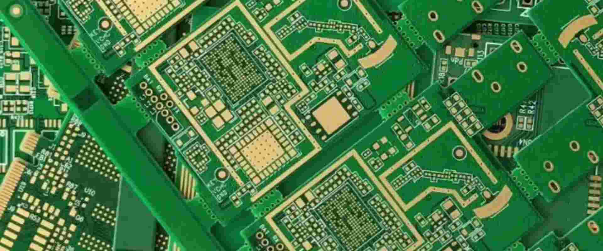
Why Choose High Dielectric PCB Material for High Speed Applications?
Reasons why choose high dielectric PCB material for high speed applications:
- Signal Integrity Boost: Stable Dk minimizes phase distortion/impedance mismatch in 10GHz+ scenarios, preventing signal reflection-induced eye closure.
- Size Optimization: Enables shorter traces (λ ∝ 1/√Dk) for compact designs like 5G mmWave arrays, reducing layer count and cost.
- Crosstalk/EMI Reduction: Enhanced field confinement reduces adjacent trace coupling, with low Df (<0.005) mitigating 77GHz automotive radar crosstalk.
- Thermal Stability: Ceramic-filled variants (e.g., MEGTRON6) maintain Dk stability <±2% across -40°C~125°C, critical for base station reliability.
- High-Frequency Adaptability: Tunable Dk (2.2–10.4) supports 24GHz/60GHz radar and satellite comms, avoiding FR-4 resonance defects.
- Power Efficiency: Low Df reduces heat generation, improving PA efficiency for 56Gbps+ SerDes in data centers.
- Design Simplification: Stable Dk enables precise impedance calculations (e.g., 50Ω lines), cutting simulation-to-production cycles for optical modules.
How to Choose PCB Dielectric Materials for High Speed Applications?
High Dielectric PCB Material Selection Guide for High Speed Applications:
1. Electrical Performance Key Parameters
Dielectric Constant (Dk)
- Low Dk Priority: Signal speed is inversely proportional to Dk. High-frequency scenarios require Dk ≤ 3.5; millimeter-wave (e.g., 28GHz) applications recommend Dk ≤ 2.2 (e.g., Taconic TLY-5, Dk=2.2±0.02@10GHz).
- Frequency Stability: Dk fluctuation ≤5% across frequencies ensures impedance matching accuracy (e.g., Rogers RO4350B maintains Dk=3.48±0.03 from 1-10GHz).
Loss Tangent (Df)
- Ultra-Low Df Dominates: Df directly determines signal attenuation. Millimeter-wave applications require Df ≤ 0.002 (PTFE substrate, Df=0.001); 5G base stations recommend Df ≤ 0.0035 to avoid 25Gbps+ signal degradation.
- Dispersion Control: Dk/Df variation ≤5% at high frequencies minimizes signal distortion.
2. Thermal-Mechanical & Reliability Requirements
Thermal Performance
- High Glass Transition Temperature (Tg ≥ 220°C): Compatible with lead-free soldering (e.g., RO4350B Tg=280°C), preventing delamination.
- Low Coefficient of Thermal Expansion (CTE ≤ 15ppm/°C): Matches copper foil to reduce thermal cycle stress (e.g., ceramic-filled PTFE CTE=12ppm/°C).
Moisture Absorption & Thermal Conductivity
- Low Moisture Absorption (≤0.01%): Moisture increases Dk/Df (FR4 Dk rises from 4.5 to 5.2 post-absorption); PTFE substrates absorb <0.01%.
- High Thermal Conductivity (≥1W/m·K): Metal-core boards (e.g., aluminum) or thermal via arrays (via diameter ≥0.3mm) enhance heat dissipation in high-power scenarios.
3. Scenario-Based Material Recommendations
| Application Scenario | Recommended Material | Core Parameters | Typical Use Cases |
| 5G Millimeter Wave (24-40GHz) | Taconic TLY-5/RO3003 | Dk=2.2, Df=0.001, Tg=280°C | Base station antennas, radar |
| High-Speed Digital (25G+) | Panasonic Megtron 7 | Dk=3.4, Df=0.002, CTE=13ppm | 400G Ethernet, AI servers |
| Satellite Communication (Ka/Ku-band) | Ceramic-filled PTFE | Dk=2.1, Df=0.001, moisture absorption 0.01% | Low-earth-orbit satellite payloads |
| Automotive Electronics (ADAS) | Shengyi S7439 (Domestic) | Dk=3.8, Df=0.004, Tg=200°C | Domain controllers, LiDAR |
| Consumer High-Frequency (5G Phones) | Rogers RO4350B | Dk=3.48, Df=0.0037, process-friendly | 5G modules, WiFi 6 routers |
4. Design Collaboration & Process Optimization
Impedance Control
- Simulation Verification: Use Polar SI9000 or ADS tools to calculate trace width/spacing based on material Dk, ensuring 50Ω±10% impedance matching.
- Differential Pair Design: Spacing tolerance ≤5% reduces crosstalk; differential impedance targets 100Ω±10%.
Stack-Up & Thermal Management
- Hybrid Laminate: High-frequency signal layers use premium materials (e.g., RO4350B), while inner power/ground planes use FR4 to balance cost/performance.
- Thermal Solutions: Metal-core boards + high-frequency dielectric layers, paired with thermal vias (diameter ≥0.3mm) for efficient heat dissipation.
Process Compatibility
- Copper Foil Selection: Very-low-profile (VLP) copper (roughness ≤2μm) for high-frequency signals minimizes skin-effect losses.
- Drilling & Plating: Laser-drilled microvias (≤0.15mm) with electroplated fill avoid burrs and reflections; hole wall roughness ≤20μm.
5. Supply Chain & Cost Considerations
- Domestic Material Alternatives: Shengyi S7G series offers Df ≤0.004 at 10GHz, 30% lower cost than imports, suitable for mid-high frequency applications.
- Lead Time Management: High-frequency substrates require 3-6 months advance procurement; RO4350B has stable inventory, while PTFE needs custom production (8-12 weeks).
- Environmental Compliance: RoHS and halogen-free compliance; ≥20% recycled content aligns with sustainability trends (e.g., ISO 14001-certified materials).
How Much Does High Dielectric PCB Material Cost?
| Material Type | Price Range (USD) | Representative Model |
| Standard FR4 | 5-8 | IS410/IT180A |
| Modified Epoxy Resin | 15-25 | Nelco N4000-13 |
| Ceramic Filled Substrate | 40-70 | Rogers RO4350B |
| PTFE High Frequency Material | 80-180 | Rogers RT/duroid 6002 |
| Special Composite Material | 200-350 | Taconic RF-35A2 (Copper included) |
Why Choose EBest Circuit (Best Technology) as High Dielectric PCB Material Supplier?
Reasons why choose us as high dielectric PCB material supplier:
- Material Performance Validation Package: Third-party certified dielectric/loss factor reports ensure precise parameter matching with design specs, eliminating guesswork in high-frequency PCB development.
- Eco-Compliance Solutions: RoHS/REACH dual-certified substrates enable seamless EU/NA market entry while boosting green brand value through regulatory compliance.
- Cost Optimization Algorithms: Proprietary stack-up design reduces BOM costs by 10-18% without compromising performance, maximizing profit margins.
- Failure Analysis Center: SEM/X-ray labs cut pilot production yield loss by 15% through root-cause diagnosis, minimizing trial costs.
- RF Application Database: 3000+ proven RF module designs provide turnkey reference from material selection to circuit layout, accelerating time-to-market.
- 24/7 Technical Support: 4h response/24h solution delivery by senior engineers resolves material application challenges, ensuring project continuity.
- Dielectric Constant Calibration: Precision tuning of dielectric properties for 5G/mmWave applications achieves 20% signal loss reduction, enhancing product competitiveness.
- Global Logistics Network: 48-hour rapid prototyping delivery supported by strategic inventory minimizes R&D cycle delays.
How to Get a Quote for High Dielectric PCB Material?
High-Dielectric PCB Material Quotation Request Checklist
1. Basic Technical Parameters
- Dielectric Constant (Dk) Range: Specify exact range (e.g., Dk=3.0±0.05)
- Loss Tangent (Df) Requirement: e.g., Df≤0.003@10GHz
- Substrate Model: Include brand/model (e.g., Rogers RO4350B, Taconic RF-35)
2. Structural Design Files
- Laminate Structure Diagram: Indicate copper thickness (e.g., 1oz/2oz) and dielectric layer thickness (mm/mil)
- Stack-Up Scheme: For multi-layer boards, provide layer sequence (e.g., PP+Core combination)
3. Process Requirements
- Surface Finish: Specify ENIG, Immersion Silver, etc.
- Special Processes: Laser drilling, blind/buried vias, impedance control tolerance (e.g., ±5%)
4. Quantity & Delivery
- Estimated Annual Volume: Phased quantities (e.g., initial order 100㎡, subsequent monthly 50㎡)
- Lead Time Requirement: Note urgency and acceptance of expedited fees
5. Certifications & Compliance
- Industry Certifications: UL Certification, IPC-4101 Standard, etc.
- Environmental Standards: RoHS/Halogen-free declaration
Welcome to contact us if you have any request for high Dk PCB material: sales@bestpcbs.com.