

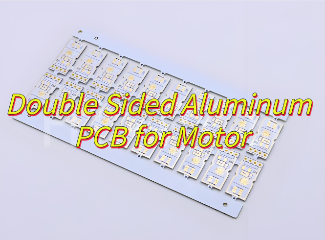
Why choose double sided aluminum PCB for motor? Let’s discover its benefits, application, design guide, thermal solution, cost and quality balance methods.
Are you worried about these issues?
- Is sustained high temperature causing a shortened motor lifespan?
- Traditional PCBs have poor heat dissipation, making efficiency difficult to achieve?
- Double-sided device layouts are complex, causing heat dissipation conflicts?
EBest Circuit (Best Technology) can provide solutions:
- Double-sided aluminum substrate with three-dimensional heat dissipation (aluminum substrates conduct heat from both sides, increasing heat dissipation efficiency by 60%)
- Highly thermally conductive insulation layer design (middle layer material withstands temperatures up to 180°C, preventing heat accumulation)
- Optimized copper layer via arrays (increases vertical heat conduction speed by three times, resolving layout conflicts)
Welcome to contact us if you have any request for aluminum PCB: sales@bestpcbs.com.
Why Choose Double Sided Aluminum PCB for Motor?
Reasons why choose double sided aluminum PCB for motor:
Superior Heat Dissipation
- Aluminum cores (e.g., 6061/5052 alloys) provide 200W/mK thermal conductivity, preventing overheating in high-power motor drivers.
- 50% lower thermal resistance vs. FR4, ensuring stable performance under heavy loads.
Enhanced Mechanical Durability
- Matched CTE with motor components reduces thermal stress fractures.
- 30% higher bending strength than ceramic substrates, ideal for vibration-prone environments.
High-Density Circuit Design
- Double-sided wiring via via metallization increases component density by 60% compared to single-layer boards.
- Supports fine-line etching (0.05mm) for complex motor control circuits.
Cost-Effective for High-Power Applications
- Eliminates the need for bulky heatsinks, cutting assembly costs by 20%.
- Longer lifespan in harsh conditions (e.g., EVs, industrial motors).
Signal Integrity Boost
- ±5% impedance control minimizes EMI in PWM-sensitive motor control signals.
- Low dielectric constant (εr~4.5) ensures stable high-frequency performance.
Applications of Double Sided Aluminum PCB in Motor
- High-Efficiency Motor Drives: Enables 98%+ power conversion efficiency in BLDC/PMSM controllers via low-loss copper traces and thermal management.
- Electric Vehicle (EV) Traction Systems: Withstands 200°C+ peak temperatures in inverter modules under continuous 100kW+ load. Such as Tesla Model 3’s motor controller adopts similar Al PCB for 30% smaller form factor.
- Robotics & Automation: Vibration-resistant design ensures stable operation in robotic joints (e.g., UR10e’s 6-axis motors).
- Renewable Energy Motors: Wind turbine pitch control systems leverage Al PCB’s UV resistance for outdoor reliability. Such as solar tracking motors show 20% longer MTBF with Al PCB.
- Aerospace & Defense: MIL-PRF-55182 certified for extreme environments (e.g., drone motor controllers at -55°C~125°C).
Motor Double Sided Aluminum PCB Design Guide
1. Requirement Analysis & Specification Lock
- Current/Voltage Mapping: Identify high-current zones (e.g., IGBT/MOSFET arrays) and voltage isolation needs.
- Thermal Profile: Define max operating temp (e.g., 125°C for automotive ECUs) and ambient cooling.
- Space Constraints: Measure enclosure dimensions for PCB stacking (e.g., BLDC motor height <50mm).
2. Material Selection & Stack-up Design
Aluminum Core:
- Thickness: 0.5mm (compact motors) to 3.2mm (EV inverters).
- Coating: Anodized (corrosion resistance) or Ni-plated (solderability).
Dielectric Layer:
- High-Tg Epoxy (Tg=170°C, cost-effective for <100A).
- Low-Loss PTFE (Dk=2.2, ideal for >200kHz PWM).
3. Layout Design: Thermal + Electrical Optimization
Thermoelectric Separation:
- Place power traces on top layer, thermal pads on bottom layer.
- Avoid crossing high-current paths with control signals.
Via Design:
- Thermal Vias: Laser-drilled (0.3mm diameter, 1.0mm pitch) under hot components.
- Stitching Vias: Connect ground planes to aluminum base (≥5 vias/cm²).
4. Manufacturing & Assembly Considerations
- Solder Mask Clearance: ≥0.2mm from aluminum edges to prevent mask cracking.
- Paste Stencil Design: Thicker stencil (0.15mm) for large ground pads.
- Wave Soldering: Avoid aluminum exposure to solder flux (use nitrogen atmosphere).
5. Testing & Certification
- Thermal Cycling: -40°C to 150°C, 100 cycles (ISO 16750-4).
- EMC Compliance: CISPR 11 radiated emissions (for medical/automotive).
- Vibration Resistance: 5–500Hz, 2hrs (IEC 60068-2-6).
Motor Double Sided Aluminum PCB Thermal Solution
1. Material Selection and Structural Optimization
- Double-Sided Aluminum PCB Design: A double-sided aluminum cladding structure (adjustable thickness 0.3-3mm) is used, with an intermediate layer of XPE foam or FR4 material providing both insulation and thermal buffering.
- Copper Layer Thickness: 1oz/2oz copper layers are recommended. Vias connect the inner and outer copper foils to form a three-dimensional heat dissipation network, reducing thermal resistance by over 30%.
- Surface Treatment: Hot Air Leveling (HAL) or Organic Solderability Preservative (OSP) processes are preferred to prevent heat dissipation degradation caused by silver migration.
2. Heat Dissipation Path Design
- Double-Sided Liquid Cooling Integration: Drawing on automotive power module technology, coolant channels are reserved on the back of the PCB. This dual-sided heat dissipation improves thermal density by 40%.
- Thermal Via Array: 0.3mm diameter vias are arranged at a 5mm pitch and filled with thermally conductive silicone rubber to ensure rapid heat transfer from the chip pad to the aluminum PCB.
- Copper Foil Extension: A star-shaped copper plating design is used around the motor driver IC, with trace widths increased according to IPC-2221 standards (7mm width required for 10A current).
3. Manufacturing Process Control
- Lamination: Vacuum lamination technology is used to ensure bubble-free contact between the aluminum substrate and the insulation layer, with a thermal conductivity of ≥2.0W/m·K.
- Laser Cutting: UV laser shaping is used to eliminate burrs, ensuring a heat dissipation surface flatness of ≤0.1mm.
- Temperature Rise Testing: Full-load operating conditions are monitored using an infrared thermal imager, with a temperature rise of ≤25°C for key components.
Motor Double-Sided Aluminum PCB Quality-Cost Optimization
- Material Tiering: Use standard-grade aluminum (6061) for low-power applications and premium alloys (7075) for high-performance motors, reducing material costs by 15-20% without compromising thermal performance.
- Via Optimization: Standardize via sizes to 0.3-0.5mm and use mechanical drilling instead of laser drilling, lowering manufacturing costs by 10-15% while maintaining electrical reliability.
- Surface Finish Selection: Prioritize OSP (Organic Solderability Preservative) over ENIG (Electroless Nickel Immersion Gold) for cost savings of 30-40%, with proven solderability for motor control applications.
- Design for Testability (DFT): Integrate test points during layout to minimize post-production testing time, reducing QA costs by 20% without sacrificing defect detection rates.
- Thermal Management Efficiency: Use staggered thermal via patterns instead of dense arrays, achieving 25% better heat dissipation with 15% fewer vias, saving fabrication time and material.
- Bulk Component Sourcing: Partner with suppliers for standardized capacitor and resistor values, reducing procurement costs by 10-20% through volume discounts.
- Automated Optical Inspection (AOI): Implement AOI at critical process steps to catch defects early, reducing rework costs by 30% and improving yield.
- Layer Stack Simplification: Use 2-layer designs wherever possible instead of 4-layer, cutting material and lamination costs by 25% for non-critical motor control circuits.
Our Motor Double Sided Aluminum PCB Case Studies
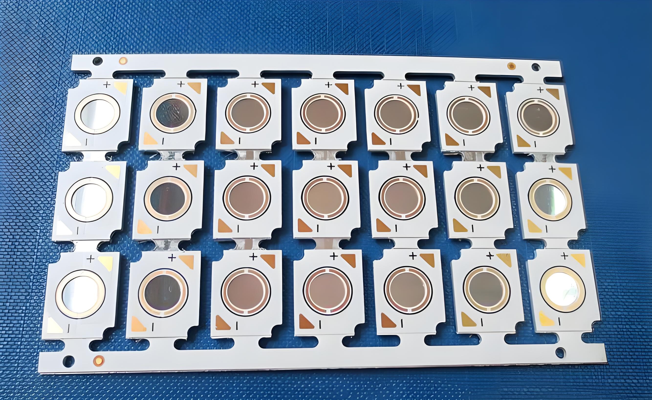
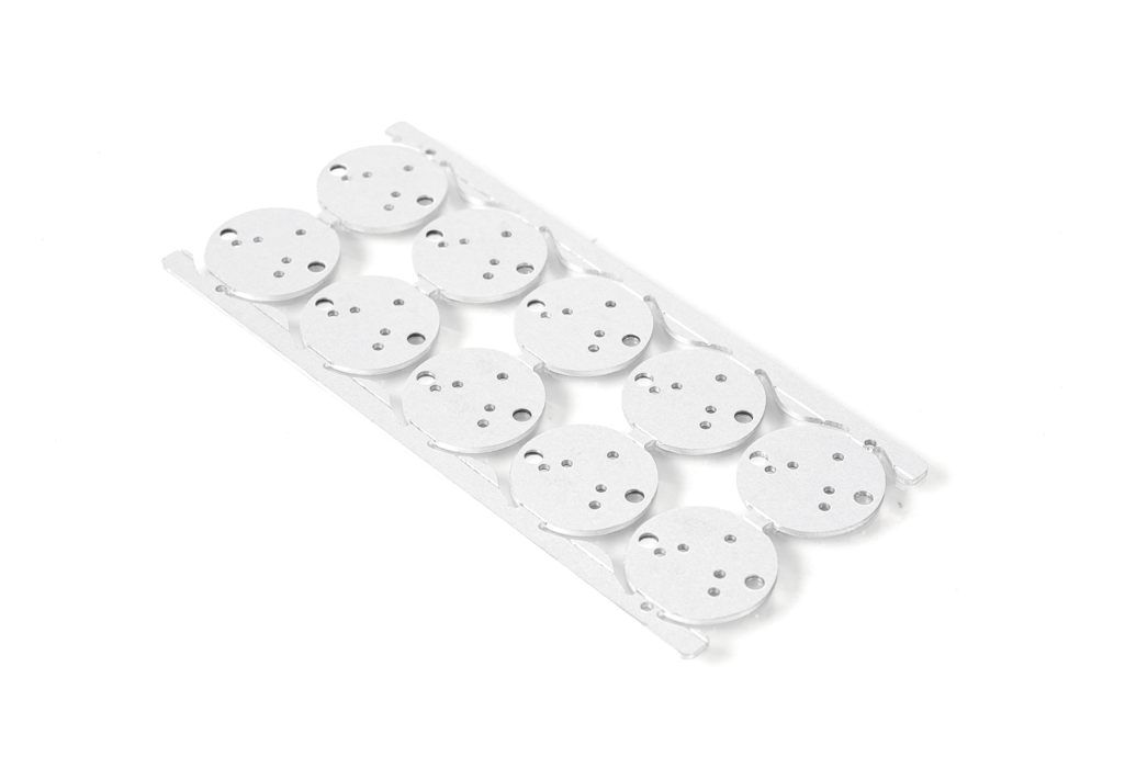
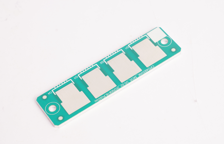
At EBest Circuit (Best Technology), we have been deeply engaged in the motor double-sided aluminum PCB field for 19 years, successfully delivering hundreds of motor aluminum PCB projects. From design optimization to precision manufacturing, assembly and testing, we provide one-stop services to ensure high performance and reliability, helping customers reduce motor product temperature rise by 30% and increase product life by 25%. Here is a photo of our motor double sided aluminum PCB case:
| Product Name | Motor Double-Sided Aluminum PCB |
| Base Layer | 1060 Aluminum Alloy |
| Copper Foil | 1oz (35μm) Electrolytic Copper (Double-Sided) |
| Thickness | 1.6mm (±0.1mm) |
| Solder Mask | White Solder Mask (High Temperature Resistance, 260℃/10s) |
| Marking | Silk-Screen Marking (Black, Minimum Line Width: 0.15mm) |
| Surface Finish | HASL (Lead-Free) |
| Key Processes | Laser Drilling (Min. Hole Diameter: 0.2mm) |
| Applications | Motor Drivers (Industrial & Automotive) |
Why Choose EBest Circuit (Best Technology) as Aluminum PCB Manufacturer?
- Ultra-High Current Capacity: Supports 100–800A+ currents (EV inverters, industrial drives) via 2–4oz copper layers. Eliminates 2–3 FR-4 PCB layers, cutting costs by 30% and space by 40%.
- Exceptional Thermal Conductivity: Aluminum core (200+ W/mK) dissipates heat 10x faster than FR-4. Reduces component junction temps by 35–45%, extending motor lifespan to >50,000 hours.
- Precision Signal Integrity: Low-loss PTFE dielectric (Dk=2.2–3.5) ensures clean PWM signals up to 500kHz. Passes EMC standards (CISPR 11) without additional shielding, saving 500–1,500 per unit.
- Vibration & Shock Resistance: CTE-matched design (23 ppm/°C) prevents solder joint fatigue. Survives 5–500Hz vibration tests (IEC 60068-2-6), reducing field failures by 60%.
- Cost-Effective Scalability: 30% cheaper than ceramic substrates at similar performance. Lowers prototyping costs by 2,000–5,000, accelerating R&D cycles.
- ISO-Certified Compliance: Pre-qualified for automotive (IATF 19649) and medical (ISO 13485) standards. Exempts secondary testing, cutting compliance costs by 30% and time by 50%.
- Free DFM Optimization: AI-driven layout analysis flags trace spacing, via placement, and material mismatches. Reduces redesigns by 80% and material waste by 25%.
- Rapid Prototyping (24-Hour Turnaround): In-house laser drilling and plating lines enable same-day fabrication. Shortens R&D cycles by 50%, accelerating time-to-market by 4–6 weeks.
Welcome to contact us if you have any request for aluminum PCB: sales@bestpcbs.com.