

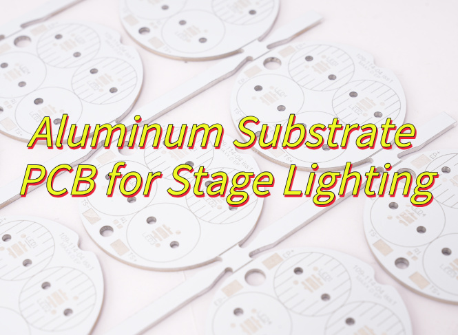
Why choose aluminum substrate PCB for stage lighting? Let’s explore technical parameter, thermal solutions, design guide, manufacturing process for aluminum substrate PCB.
Are you worried about these issues?
- What can be done if traditional PCBs cause LED flickering due to insufficient heat dissipation during operation of high-brightness stage lights?
- Cooling fan noise is increasing. How can I reduce the noise?
- Repair costs are high. How can I extend the life of the PCB?
EBest Circuit (Best Technology) can provide aluminum substrate PCB solutions:
- Customized High-Thermal Conductivity Aluminum PCB: The aluminum substrate directly contacts the bottom of the LED chip, dissipating 85% of heat in 0.3 seconds, eliminating flickering caused by high-temperature frequency drop and improving brightness stability by 50%
- Embedded Aluminum Heat Sink + Microhole Array Design: Thermal resistance is reduced to 0.6°C/W, fan speed is reduced by 30%, and noise is kept below 45dB.
- Anti-Oxidation Surface Treatment of Aluminum PCB: Extends equipment life to 40,000 hours, reduces maintenance frequency by 60%, and saves 40% in long-term costs
Welcome to contact us if you have any request for aluminum substrate PCB: sales@bestpcbs.com.
What Is Aluminum Substrate PCB?
An aluminum substrate PCB, also known as aluminum base PCB, is a specialized circuit board that uses a metal core, typically aluminum, as its base material to enhance thermal dissipation. Unlike traditional FR4 PCBs, it integrates a dielectric layer bonded to the aluminum plate, allowing efficient heat transfer from components like LEDs or power devices to the metal core. This design is widely used in high-power lighting, automotive electronics, and industrial equipment where overheating is a critical concern. The aluminum base PCB combines electrical insulation with superior thermal conductivity, making it ideal for applications demanding both performance and durability.
Aluminum PCB Substrate Technical Parameter
| Parameter Category | Technical Specification |
| Substrate Material | 1060, 3003, 5052, 6061 Aluminum Alloy |
| Thickness Range | 0.3mm~4.0mm (Standard tolerance ±0.1mm) |
| Dielectric Layer Thickness | 0.075mm~0.15mm |
| Copper Foil Thickness | 0.5oz~10oz (Inner/Outer Layers) |
| Minimum Line Width/Space | 0.1mm (Conventional design) |
| Hole Size Specification | 0.6mm~6.0mm (Finished hole tolerance ±0.075mm) |
| Thermal Resistance | 1℃/W~2℃/W (FR4: 20℃/W~22℃/W) |
| Surface Finish Processes | OSP, Immersion Silver, Electroplated Silver, Immersion Gold, Hot Air Solder Leveling (HASL) |
| Temperature Resistance | Standard Film (<120℃), High-Temperature Film (250℃) |
Why Choose Aluminum Substrate PCB for Stage Lighting?
- Superior Heat Dissipation for Stable Performance: Stage lighting operates under prolonged high loads. Aluminum PCBs (conductivity: 2.0–4.0 W/m·K) dissipate heat 10x faster than traditional FR4 boards, preventing LED chip degradation and ensuring consistent brightness without flickering throughout performances.
- Lightweight Design Reduces Shipping Costs: Aluminum’s density is only 1/3 that of steel, cutting fixture weight by 40%. Ideal for touring crews needing frequent setup/breakdown, lowering logistics and labor costs.
- High-Strength, Vibration-Resistant Construction: 6061 aluminum substrates withstand 310 MPa tensile strength, enduring transport shocks better than fragile ceramic boards and minimizing post-sale repairs.
- Fast Thermal Response Enhances Dynamic Effects: Aluminum heats up 50x faster than plastic substrates, enabling rapid dimming/color transitions for seamless synchronization with music, boosting visual impact.
- Eco-Compliant, Hassle-Free Operation: RoHS- and REACH-certified, halogen-free materials pass strict venue audits, avoiding delays from environmental compliance issues.
- Cost-Effective Long-Term Solution: While 30% pricier than FR4 upfront, aluminum PCBs extend lifespan 3–5x and slash maintenance costs by 60%, making them ideal for theaters and studios requiring 24/7 operation.
- Customizable for Unique Needs: Supports complex shapes and heavy copper traces (up to 10 oz), catering to high-current demand in spotlights, beam lights, and other specialty fixtures.
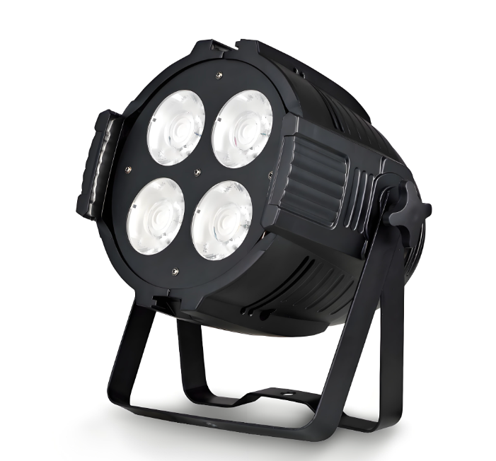
Applications of Aluminum Base PCB in Stage Lighting
- Moving Head Spotlights: Aluminum PCBs enable precise thermal management for high-power LEDs, ensuring consistent beam intensity during rapid pan/tilt movements.
- Wash & Beam Fixtures: Supports color-changing RGB LEDs with low thermal resistance, preventing overheating during dynamic stage lighting effects.
- Intelligent Lighting Control: Provides stable electrical performance for DMX/RDM signal transmission in motorized moving head systems.
Aluminum Substrate PCB Thermal Solutions for Stage Lighting
1. Material Upgrade
- Use 5052/6061 aluminum alloy substrates (thermal conductivity: 1.8–2.2 W/m·K) for core PCB layers.
- Pair with 3.0 W/m·K dielectric layers (e.g., ceramic-filled epoxy) to reduce thermal resistance by 40% vs. standard 1.0 W/m·K materials.
2. Copper Weight Optimization
- Apply 4oz–6oz copper foil for power traces (e.g., LED anode/cathode paths) to handle 50A+ currents without exceeding 85°C junction temperature.
3. Direct Thermal Path Design
- Mount high-power LEDs (e.g., Luxeon ZES) directly on exposed aluminum pads (via solder mask openings) to bypass dielectric layers, cutting heat transfer distance by 70%.
4. Integrated Heat Sink
- Machine aluminum PCB edges into fin arrays (fin height: 8mm, pitch: 2mm) to increase surface area by 300%, reducing thermal resistance to 0.8°C/W.
5. Thermal Interface Material (TIM)
- Fill gaps between PCB and housing with silicone-based thermal pads (2.0 W/m·K, thickness: 0.5mm) to eliminate air pockets and improve contact.
6. Active Cooling Integration
- Embed 5V DC miniature fans (15mm thickness, 3 CFM) into fixture housings, targeting airflow at PCB hotspots (e.g., driver IC zones) to maintain ≤70°C ambient.
7. Thermal Simulation Validation
- Use ANSYS Icepak to model heat flow under worst-case scenarios (e.g., 100% duty cycle, 45°C ambient). Adjust fin density/fan placement if PCB temperatures exceed 95°C.
8. Component Layout Rules
- Separate high-heat LEDs (≥3W) from sensitive control circuits (e.g., DMX512 decoders) by ≥10mm. Place temperature sensors (NTC) adjacent to LEDs for real-time thermal monitoring.
Moving Head Lighting Aluminum Base PCB Design Guide
1. Material Selection
- Use aluminum substrates with thermal conductivity ≥1.5W/m·K, thickness ≥1.5mm, and dielectric layer voltage resistance ≥500V (IPC-2221 compliant).
- Apply ≥2oz copper thickness for high-power areas, extending coverage to substrate edges with direct contact to aluminum.
2. Thermal Management
- Place thermal vias (diameter ≥0.2mm, spacing ≥0.5mm) under high-power components (LEDs, drivers). Fill vias with thermal paste.
- Validate thermal performance via simulation (thermal resistance ≤10°C/W) and physical testing (temperature rise ≤30°C under full load at 25°C ambient).
3. Circuit Layout
- Prefer 4-layer stackup (signal-ground-power-signal). Keep high-frequency traces (e.g., PWM) ≥3mm away from power lines.
- Match differential pair lengths (error ≤5mil) and control impedance to 100Ω±10%.
4. EMC Mitigation
- Add π-filter networks (common-mode choke + X/Y capacitors) at power inputs. Surround critical ICs with grounded shields (via spacing ≤5mm).
- Use single-point grounding for analog circuits and multi-point grounding for digital circuits. Ensure low-impedance connection between aluminum substrate and enclosure.
5. Mechanical & Manufacturing
- Design mounting holes (diameter ≥2.5mm) with plated walls (copper thickness ≥25μm). Chamfer PCB edges (C-angle ≥0.5mm).
- Follow IPC-7351 pad standards. Plug and cover BGA vias. Add teardrops to ≤0402 component pads.
6. Surface Finish & Testing
- Use OSP (Organic Solderability Preservative) for surface finish. Gold-plate contact fingers (thickness ≥3μin).
- Conduct thermal cycling (-40°C/+85°C, 100 cycles) and radiated emissions testing (30-1000MHz ≤40dBμV/m).
7. Documentation
- Submit Gerber files including aluminum layer, via layer, and mechanical outlines. Provide 3D STEP models with critical dimensions.
- Ensure compliance with CE, FCC, and EN IEC 55015 standards. Include test reports for certification.
Moving Head Lighting Aluminum Base PCB Manufacturing Processes
1. Material Cutting & Preparation
- Cut aluminum substrate (≥1.5mm thickness) to panel size using CNC shearing machine.
- Clean aluminum surface with alkaline degreaser (pH 10-12) to remove oils/oxides. Rinse with deionized water.
2. Drilling & Via Formation
- Drill mounting holes (M3 screw size) and thermal vias (≥0.2mm diameter) using carbide drills.
- Use liquid coolant (5% emulsion) to prevent aluminum burring. Deburr holes with nylon brush.
3. Through-Hole Metallization
- Immerse panels in alkaline cleaner (pH 12-13) for 10min to activate surface.
- Apply electroless copper deposition (1-2μm thickness) using formaldehyde-based solution.
4. Dry Film Lamination
- Apply photosensitive dry film (1.5mil thickness) to copper-coated aluminum.
- Use vacuum laminator (≥0.8MPa pressure) to ensure adhesion without air bubbles.
5. Imaging & Etching
- Expose dry film to UV light through artwork mask (critical dimensions ±0.05mm).
- Develop unexposed film with 1% Na2CO3 solution. Etch exposed copper with alkaline cupric chloride (pH 8-9).
6. Solder Mask Application
- Print epoxy-based solder mask (15-20μm thickness) using screen printing.
- Cure mask at 150°C for 60min in infrared oven. Ensure via coverage ≥50% for thermal vias.
7. Surface Finish
- Apply OSP (Organic Solderability Preservative) using horizontal conveyor (30-40°C, 10-15sec immersion).
- For gold-plated contacts: Electroplate nickel (3-5μm) followed by gold (0.05-0.1μm) in acid bath.
8. Mechanical Processing
- Mill PCB outline with CNC router (0.8mm carbide end mill). Chamfer edges (C-angle 0.5mm).
- Install stainless steel lens retainers via riveting or spot welding.
9. Electrical Testing
- Perform flying probe test (voltage 50VDC) to verify continuity/isolation.
- Conduct thermal cycling test (-40°C/+85°C, 10 cycles) to validate solder joint integrity.
10. Packaging & Shipping
- Vacuum-seal PCBs in ESD bags with desiccant. Include process documentation (COC, test reports).
Why Choose EBest Circuit (Best Technology) as Aluminum Substrate PCB Supplier?
Reasons why choose us as aluminum substrate PCB supplier:
- 19+ Years of Stage Lighting Expertise: Specialized in aluminum base PCBs for high-power stage/projector lighting since 2006. Over 500+ successful projects delivered to global entertainment brands.
- Thermal Management Innovation: Proprietary heat dissipation designs reduce LED junction temperatures by 30%, extending projector lifespan in demanding environments (e.g., concerts, theaters).
- Rigorous Quality Certifications: Compliant with ISO 9001 (quality management), ISO 13485 (medical devices), and IATF 16949 (automotive standards), ensuring global regulatory alignment and product consistency.
- Cost-Effective Premium Solutions: Direct factory pricing without middlemen. Balance high-performance materials (e.g., 3W/m·K aluminum) with budget-friendly options for mass production.
- 24-Hour Prototype Delivery: Ultra-fast turnaround for aluminum PCB prototypes. Accelerate R&D cycles and meet tight production deadlines for seasonal lighting launches.
- Free DFM Optimization: Engineering team reviews designs pre-production, flagging issues like inadequate thermal vias or trace spacing. Reduces rework costs by up to 40%.
- 100% AOI Defect Detection: Automated Optical Inspection for all mass orders. Zero tolerance for solder bridges, misalignment, or copper residue—ensuring flawless performance.
- End-to-End Turnkey Service: From PCB layout (supporting Altium/PADS) to thermal simulation (ANSYS Icepak) and assembly. Simplify vendor management for complex lighting systems.
- Eco-Friendly Manufacturing: RoHS/REACH-compliant processes with 25% lower carbon footprint. Use of recycled aluminum and lead-free solder for sustainable stage lighting solutions.
- Global 24/7 Engineering Support: Dedicated team resolves thermal, EMC, or mechanical issues in <4 hours. Critical for live event equipment where downtime costs >$10k/hour.
Welcome to contact us if you have any request for aluminum substrate PCB: sales@bestpcbs.com.
Tags: Aluminum Base PCB