

What is a VFD control panel? This guide comprehensively covers its components, functions, installation, wiring, design, manufacturer selection, and cost analysis.
- Does your VFD control panel have poor heat dissipation and short life due to poor PCB design?
- Is the delivery delayed due to unstable supply chain, affecting the project progress?
- Traditional solutions are costly and slow to iterate. How to balance performance and cost performance?
EBest Circuit (Best Technology) Can Provide Service:
- One-stop PCBA service – control the entire process from design to mass production, optimize the heat dissipation layout, and improve the durability of the panel by 30%+.
- Agile supply chain – own PCB factory + strategic cooperation component supplier, ensure fast delivery within 15 days, error rate <0.5%.
- Cost optimization solution – provide high compatibility circuit design, support flexible iteration, and reduce batch cost by 20%.
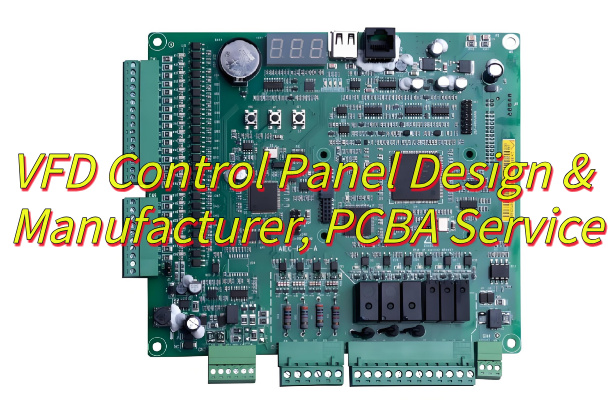
What Is VFD Control Panel?
A VFD control panel is the dedicated operator interface unit for managing variable frequency drives (VFDs), providing direct controls to start, stop, and adjust motor speed or torque through tactile buttons, digital displays, and parameter-setting menus. It enables real-time monitoring of operational status including frequency output, current levels, and fault diagnostics while supporting both manual inputs and automated external signal integration via communication terminals. The panel features protective enclosures for industrial environments, application-specific configuration options, and energy optimization capabilities through precise motor speed regulation based on load requirements.
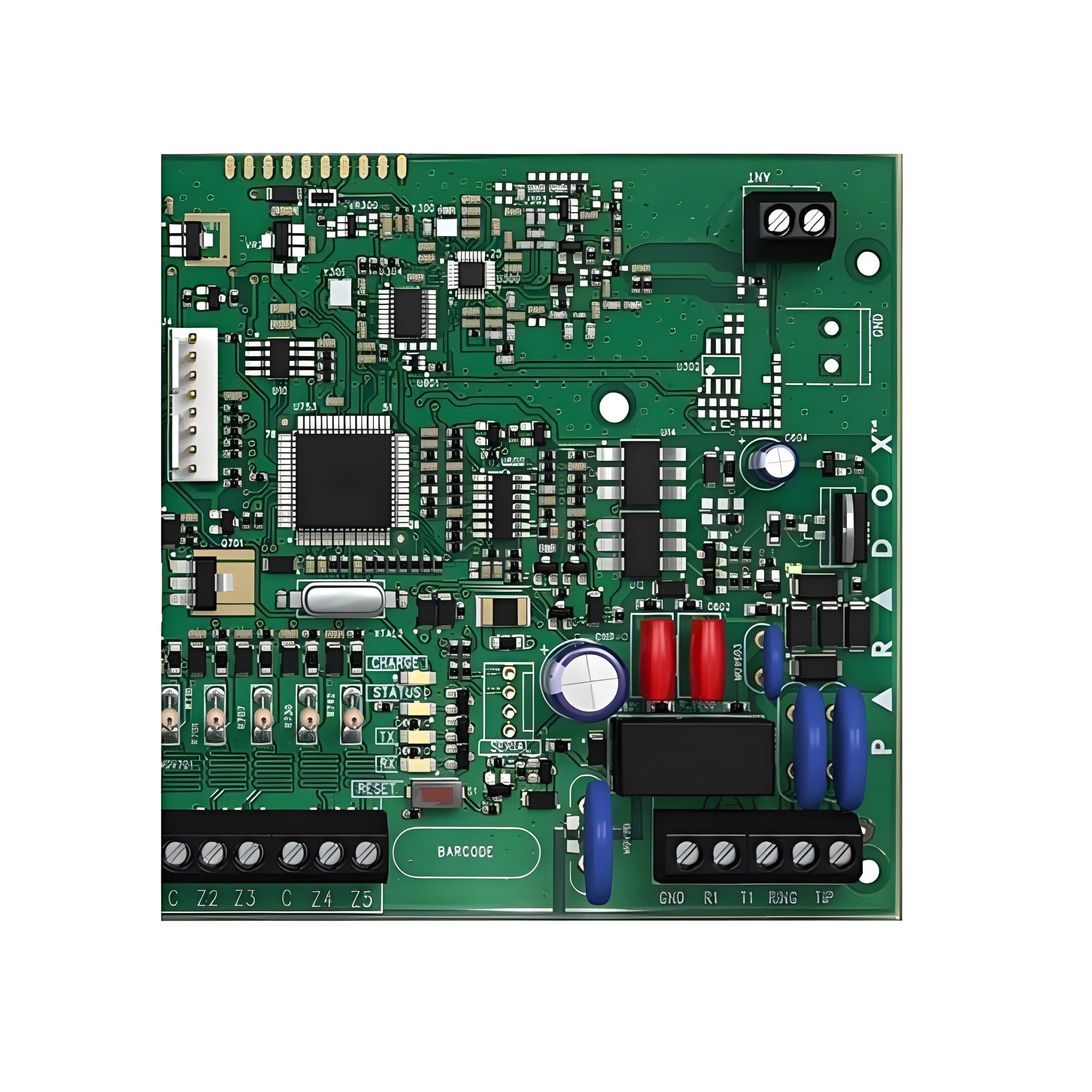
VFD Control Panel Components & Specification
| Component | Specification |
| Power Conversion | Rectifier (AC-DC), DC bus with capacitors, IGBT-based inverter (DC-AC) |
| Protection Devices | Circuit breakers, line reactors (harmonic suppression), surge suppressors |
| Operator Interface | Tactile buttons, digital displays (frequency/current/voltage), potentiometers for speed adjustment |
| Control Logic | Microcontroller with vector control (sensorless), PID, multi-speed presets, RS485/CAN bus communication |
| Terminal Connections | I/O terminals for PLCs, sensors (0-10V/4-20mA), external control signals |
| Cooling System | Fans or heat sinks (thermal management for IGBT/inverter modules) |
| Enclosure | NEMA 3R/4/4X rated (dust/water/corrosion resistance) |
| Optional Bypass | Contactor-based manual bypass for direct mains operation during maintenance |
| Motor Compatibility | 0.2–300 kW power range, configurable for induction/PMSM motors (V/f or vector control) |
| Environmental Ratings | Operating temperature: -10°C to +50°C; humidity: 10–90% non-condensing |
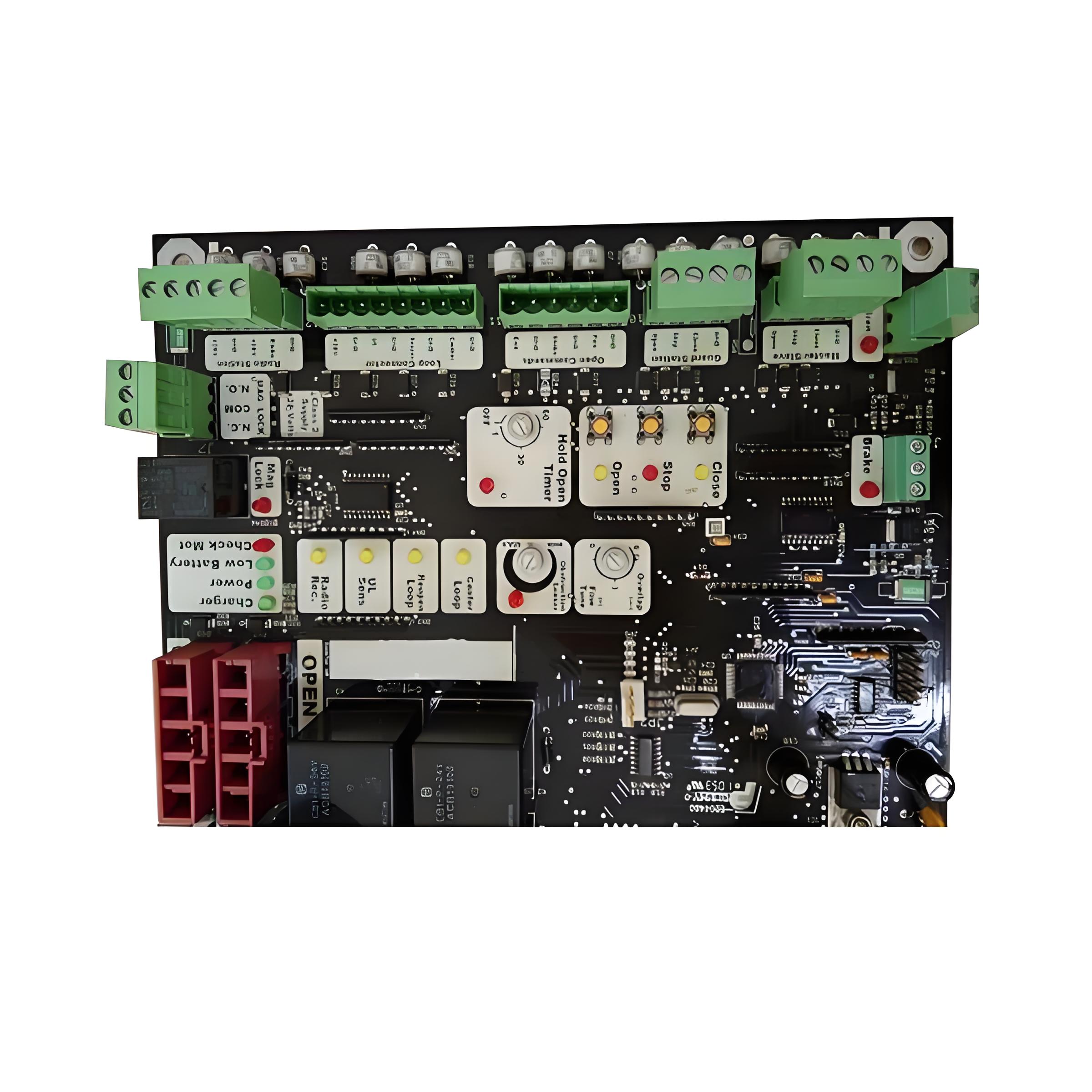
What Are Function of VFD Control Panels?
- Precise Control of Motor Speed and Torque: Adjusts output frequency and voltage to achieve accurate regulation of motor speed and torque, adapting to dynamic requirements of different loads (e.g., constant torque, variable torque).
- Energy-Saving Optimized Operation: Automatically adjusts motor speed based on actual load (e.g., for fan, pump loads), avoiding energy waste during constant-speed operation and significantly reducing energy consumption.
- Comprehensive Equipment Protection: Integrates multiple protection functions (overcurrent, overvoltage, undervoltage, overtemperature, short circuit), with real-time monitoring of abnormal operating conditions to trigger protective actions and prevent damage to the motor and VFD.
- Real-Time Status Monitoring and Fault Diagnosis: Displays key parameters (current, voltage, frequency, temperature) via HMI or communication interfaces, logs fault codes, and provides data support for maintenance and diagnostics.
- Human-Machine Interaction and Local Control: Offers an operator panel (HMI) for local parameter settings (e.g., frequency reference, acceleration time), mode switching (manual/automatic), and start/stop control, simplifying user operations.
- Industrial System Integration and Communication: Supports mainstream communication protocols (e.g., RS485, Modbus, Profinet) for data interaction with upper-level systems (PLC, DCS), enabling integration into industrial automation networks for remote monitoring and centralized management.
- Safe Handling of Regenerative Energy: During motor deceleration or braking, converts regenerative energy into heat dissipation via the braking unit and braking resistor, preventing excessive DC bus voltage and ensuring system safety.
VFD Control Panel Installation Notes
- Environmental Conditions: Install in dry, dust-free area with 0°C–40°C (32°F–104°F) ambient temp. Avoid corrosive gases, vibrations, and direct sunlight.
- Ventilation & Clearance: Maintain ≥100mm (4in) space on all sides. Avoid enclosed cabinets without forced cooling.
- Power Supply: Use dedicated circuit with correct breaker/fuse rating. Avoid sharing lines with high-interference devices.
- Grounding: Connect chassis to low-impedance ground (≤10Ω). Use independent AWG 14+ grounding wire, separate from motor/power grounds.
- Cable Routing: Separate power/control cables by ≥200mm (8in). Use shielded control cables; ground shields at one end.
- Motor Wiring: Use cables rated ≥150% of VFD current. Tighten terminals; add ferrite cores for cables >50m (164ft).
- Braking Resistor: Install away from flammables. Ensure terminals are insulated and rated for max braking current.
- Operator Panel: Mount HMI in accessible, vibration-free spot. Use IP65 enclosures for outdoor/harsh environments.
- EMC Compliance: Install EMC filters near VFD if needed. Connect filter grounds directly to chassis.
- Post-Installation Checks: Tighten all connections. Perform insulation test (>1MΩ at 500V DC). Verify parameters match motor/load. Run no-load test before full operation.
VFD Control Panel Wiring Technique
- Cable Type Selection: Use shielded twisted-pair (STP) for control/signal lines; copper power cables rated ≥150% of VFD current.
- Power/Control Separation: Route power and control cables in separate conduits with ≥200mm (8in) spacing to minimize EMI.
- Shield Grounding: Ground STP shields at one end (VFD side) only; avoid ground loops. Add ferrite cores for long control lines.
- Motor Cable Length: For cables >50m (164ft), use output reactors or VFD-rated cables to prevent voltage reflection.
- Terminal Torque Control: Tighten terminals to manufacturer torque specs (e.g., 0.6-0.8N·m for M4); re-torque after initial operation.
- Braking Resistor Wiring: Connect with cables rated for peak braking current; use a dedicated breaker rated 1.5× resistor’s continuous current.
- Grounding Priority: Use star-type grounding with dedicated busbar (≤10Ω impedance); avoid daisy-chaining PE connections.
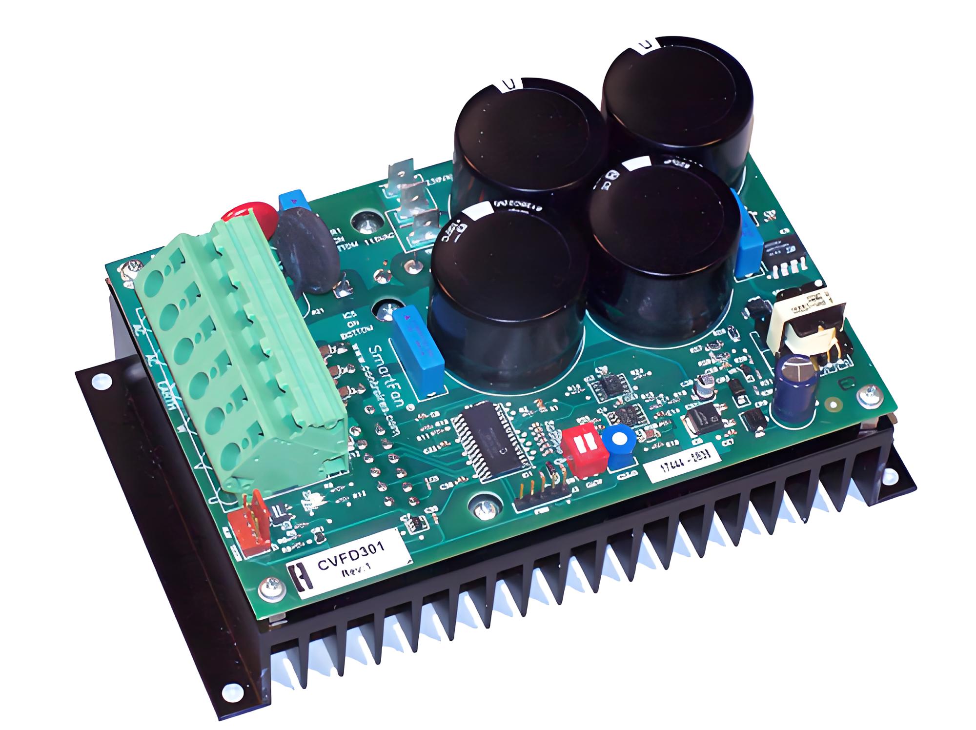
How to Design a Variable Frequency Drive Control Panel?
Below are VFD control panel design processes:
1. Power Circuit Design
Busbar Engineering:
- Material selection: Electrolytic copper (C11000) with 35μm tin plating.
- Current density: 1.2A/mm² for natural convection cooling.
- Edge spacing: 8mm/kV for 480V systems per UL 508A.
2. Thermal Management
Heat Dissipation Calculation:
- Losses = (1 – η) × Pout × duty cycle.
- Required heatsink θsa = (Tjmax – Tamb)/Pdiss – θjc – θcs.
- Example: 50HP drive requires 0.15°C/W heatsink with forced air (2m/s).
3. EMC Compliance
Filter Configuration:
- 3-stage RFI filter (X/Y capacitors + common mode choke).
- Shielding: 360° termination of cable shields using EMC glands.
- Grounding: Single-point star grounding with <2.5mΩ impedance.
4. Protection Systems
Arc Flash Prevention:
- Optical sensors with <5ms response time.
- Current-limiting fuses with I²t let-through <20% of incident energy.
- Zone-selective interlocking for cascaded protection.
5. Control Wiring Best Practices
Segregation Rules:
- 50mm separation between power (>60V) and control circuits.
- Cross at 90° when unavoidable.
- Use twisted pair (1 twist/cm) for analog signals.
6. Validation Protocol
- Hi-pot test: 2× rated voltage + 1000V for 60s
- Thermal imaging: Verify <65°C hotspot temperature
- Vibration test: 5-500Hz sweep at 1.5g (3 axes)
How to Choose a Reliable VFD Control Panel Manufacturer?
Methods about how to choose a reliable VFD control panel manufacturer:
Product Reliability & Quality
- Verify use of brand-name components (e.g., ABB, Schneider, Siemens).
- Check for third-party certifications (UL 508C, IEC 61439).
- Request test reports (insulation, short-circuit withstand).
Manufacturer Experience & Reputation
- Choose >10 years in VFD panel production.
- Review industry-specific case studies (e.g., pumps, HVAC).
- Confirm in-house engineering (not outsourced design).
Customization Capability
- Ensure layout flexibility (HMI/PLC integration, bypass contactor).
- Confirm multi-VFD/brand support (e.g., Danfoss + Allen-Bradley).
- Request prototype testing for custom designs.
Technical Support & After-Sales Service
- Prioritize <4h response time for critical issues.
- Confirm on-site engineers (available within 24–48h).
- Verify local spare parts inventory.
Cost & Delivery Time
- Compare quotes from 3+ manufacturers (avoid lowest bidder).
- Confirm lead time (standard: 2–4 weeks; custom: 6–8 weeks).
- Negotiate payment terms (e.g., 30% advance, 70% post-FAT).
Compliance & Safety Standards
- Ensure local regulations (NEC, IEC) compliance.
- Verify CE/UL/CSA markings on enclosures.
- Check IP rating (e.g., IP55 for outdoor, IP20 for indoor).
What Factors Affect the Price of VFD Control Panel?
Power Rating
- Higher kW/HP = larger VFD, breaker, and cables. Example: A 50kW panel costs 2–3× more than a 10kW unit.
Component Brand
- Premium brands (ABB, Schneider) cost 20–50% more than generic alternatives but offer longer lifespans.
Enclosure Type
- Stainless steel (IP65/NEMA 4X): +30–50% vs. standard steel.
- Explosion-proof (ATEX/IECEx): +2,000–10,000.
Customization
- HMI/PLC integration: +500–5,000.
- Multi-drive systems (2+ VFDs): +40–80% cost.
- Communication protocols (Modbus, Profinet): +1,000–3,000.
Certifications
- UL 508C/IEC 61439 compliance: +10–20%.
- Hazardous area approvals (ATEX): +15–30%.
Warranty & Support
- Extended warranty (3–5 years): +5–10%.
- On-site commissioning: +1,000–5,000.
Conclusion
In summary, VFD control panels require precise design for motor speed regulation, energy efficiency, and industrial automation applications. This guide has covered their core components (including IGBT modules and EMC filters), installation standards (per IEC 61800-5-1), and advanced wiring techniques. For optimal performance, partner with EBest Circuit (Best Technology) for professional PCBA service, our certified manufacturing processes ensure compliant, high-reliability panels with thermal management up to 60°C ambient. Contact us today for cost-effective solutions tailored to your project requirements: sales@bestpcbs.com.