

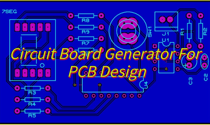
Seeking for circuit board generator for your design? This guide covers automated pattern/font generation, error reduction, and signal integrity optimization, helping you save time and costs at every stage.
EBest Circuit (Best Technology) stands out as your ideal PCB design partner with tangible benefits that accelerate your projects. We provide free DFM analysis with every design to prevent costly manufacturing errors upfront. Our pricing is transparent and competitive with no hidden charges. When you need support, our 24-hour response team delivers solutions faster than industry standards. What truly differentiates us is our dedicated designer team offering real-time 1-on-1 consultations to address your specific challenges.
With 18+ years of specialized experience, we’ve optimized our circuit board generators to handle complex multilayer designs while maintaining 99.2% first-pass success rates. Let us prove how our combination of technical expertise, cost efficiency and responsive service can streamline your PCB development – contact us today for a risk-free consultation: sales@bestpcbs.com.
What Is a Circuit Board Generator?
A circuit board generator is a specialized system that translates electronic circuit designs into functional printed circuit boards (PCBs). It bridges the gap between schematic diagrams and physical hardware.
Software circuit board generators automate PCB layout creation. They handle component positioning, copper trace routing according to electrical requirements, and manufacturability checks. These tools produce essential industry-standard output files like Gerber formats, accelerating development for complex designs such as multi-layer boards or high-frequency circuits.
Physical circuit board generators directly create prototype boards using methods like milling, etching, or additive printing. This enables tangible board production within hours for rapid testing. Specialized versions also exist for creating custom silkscreen markings, electromagnetic shielding patterns, or experimental circuit configurations.
By efficiently translating electronic concepts into manufacturable realities, circuit board generators streamline the entire development cycle, ensuring designs meet fabrication standards while dramatically shortening prototyping time.
What Are Software For Circuit Board Generator?
Here are software tools for circuit board generator:
- Schematic Capture Interface: This foundational tool allows designers to create the logical diagram of the circuit using standardized electronic symbols. It precisely defines component connections, establishing the functional blueprint before physical layout begins.
- Component Library Manager: Comprehensive libraries store detailed information on parts, including schematic symbols, physical footprints (pad shapes, sizes), 3D models, and electrical parameters. This prevents errors and streamlines component selection and placement.
- Placement Assistance: Tools provide visual cues and automated suggestions for positioning components on the board layout. Designers maintain control while benefiting from optimized arrangements that minimize trace lengths and consider thermal or signal constraints.
- Interactive Routing Engine: This facilitates creating physical copper connections (“traces”) between component pins, offering manual, semi-automated, or fully automated modes. Intelligent routing adheres to spacing rules, manages complex paths (like differential pairs), and ensures signal integrity.
- Real-time Design Rule Checker (DRC): Operating continuously, this enforces user-defined and fabrication constraints (trace width, spacing, hole sizes). Immediate feedback on violations prevents costly errors reaching manufacturing.
- Manufacturing File Generator: Upon successful verification, the system automatically exports industry-standard files essential for production, including Gerber files (copper layers, solder mask, silkscreen) and drill files (Excellon format).
- Signal Integrity Analyzer: Integrated simulation tools model how electrical signals behave on traces. This helps predict and mitigate issues like noise, reflections, or timing errors before prototyping, enhancing reliability.
- Power Integrity Analysis Tool: Dedicated features analyze voltage stability and current distribution across the board, identifying potential drops or excessive noise that could impact circuit performance.
- 3D Visualization & Mechanical Integration: Tools render the board and components in 3D, enabling collision checks with enclosures or other mechanical parts. This ensures physical fit and compatibility early in the design cycle.
- Bill of Materials (BOM) Generator: Automatically extracts a complete list of all required components directly from the design data, simplifying procurement, cost estimation, and assembly preparation.
- Version Control & Data Management: Integrated systems track design revisions, manage project files, and support collaborative workflows, safeguarding progress and enabling efficient team coordination.
- CAM Processor Interface: While distinct from the generator core, robust interfaces allow seamless data transfer to specialized CAM (Computer-Aided Manufacturing) software for final fabrication preparation and panelization. This ensures smooth handoff to manufacturing partners.
What Are Function of Circuit Board Generator?
Function of circuit board generator:
- Translating Schematics into Physical Layouts: The circuit board generator converts logical circuit diagrams into precise, manufacturable board geometries. This ensures the electrical connections defined in the schematic are accurately reflected in the physical copper pathways and component placement.
- Managing Comprehensive Component Libraries: It centrally stores and organizes detailed information for every part used. This includes schematic symbols, footprints (defining physical pad layouts and outlines), 3D models, and electrical parameters, guaranteeing consistency and preventing placement or assembly errors.
- Facilitating Intelligent Component Placement: While designing, the circuit board generator provides visual aids and automated suggestions based on connectivity and design rules. This assists in arranging components efficiently, minimizing trace lengths for better signal performance, managing heat distribution, and respecting mechanical constraints.
- Enabling Rule-Driven Routing: The generator offers powerful tools for creating the copper traces connecting components. Designers can route manually, use guided assistance, or employ automation – all while strictly adhering to spacing rules, managing impedance for sensitive signals, and avoiding electrical conflicts.
- Enforcing Real-Time Design Rules: Continuously, the circuit board generator checks the layout against predefined manufacturing tolerances (trace width, spacing, hole sizes) and electrical requirements. Immediate feedback on violations prevents costly errors from reaching fabrication, saving significant time and money.
- Generating Essential Manufacturing Files: Upon design completion and verification, the circuit board generator automatically exports the complete set of industry-standard files required for production. These include Gerber files for each copper layer, solder mask, and silkscreen; Excellon drill files; assembly drawings; and accurate Bills of Materials (BOM).
- Supporting Early Electrical Verification: Through integrated simulation, the circuit board generator allows designers to analyze signal behavior and power distribution stability before physical prototypes exist. Identifying potential issues like noise or voltage drops at this stage significantly reduces later development risks and costs.
- Producing Functional Prototypes: When connected to compatible milling or printing equipment, the circuit board generator directly drives the machinery to create tangible, working prototype boards within a short timeframe. This accelerates testing and validation cycles dramatically.
What Are Applications of Circuit Board Generator?
Applications of circuit board generator:
- Consumer Electronics – Designs compact boards for smartphones, wearables, and smart home devices
- Industrial Systems – Creates durable control boards for factory equipment and power systems
- Automotive Tech – Develops reliable vehicle electronics for engine control, ADAS, and EV batteries
- Aerospace & Defense – Produces ultra-reliable boards for aircraft systems and military equipment
- Medical Devices – Enables precise circuits for diagnostic machines and implantable devices
- Telecom Equipment – Builds complex boards for network infrastructure and communication systems
- IoT Devices – Designs connected sensors and smart controllers with wireless capabilities
- Energy Systems – Creates boards for solar inverters, wind turbines, and smart grid technology
- Robotics – Develops control circuitry for industrial robots, drones, and automated systems
- Education & Research – Supports academic learning and rapid prototyping for new technologies
Why Choose a Circuit Board Pattern Generator for RF PCB Designs?
Reasons why choose a circuit board pattern generator for RF PCB designs:
- Save Time on Repetitive Tasks: Instead of manually drawing common patterns (like ground planes or RF shields), the generator automates these layouts. This means you can focus on custom parts of your design, reducing hours of work to minutes.
- Reduce Human Errors: Manual tracing risks small mistakes—misaligned vias or uneven spacing. Automated patterns ensure consistency, especially for high-frequency designs where precision matters.
- Test Ideas Faster: Quickly generate multiple pattern variations (e.g., different antenna shapes or thermal reliefs) to compare performance in simulations. Ideal for prototyping phases.
- Simplify Complex Geometries: For advanced needs like curved traces or fractal-based layouts, the tool handles math-heavy optimizations you’d otherwise calculate manually.
- Standardize Designs Across Teams: Share pre-validated patterns (e.g., EMI shields or power distribution networks) with colleagues, ensuring everyone uses the same reliable templates.
- Adapt to Material Constraints: Some generators adjust patterns based on your PCB’s dielectric properties or manufacturing limits, avoiding costly post-design fixes.
- Enhance Aesthetics Without Sacrificing Function: Create visually appealing boards (e.g., artistic logos or decorative elements) while maintaining electrical integrity—useful for consumer electronics.
- Lower Learning Curve for New Designers: Beginners can leverage pre-built patterns to understand best practices, like proper via stitching or impedance matching, without deep prior experience.
How a Circuit Board Font Generator Saves Time in Custom Marking Design?
Automated Font Compliance
- PCBs require silkscreen markings that adhere to manufacturing standards (e.g., minimum line width, spacing). Font generators automatically apply industry-compliant fonts, ensuring legibility without manual adjustments. This prevents costly reworks caused by non-conforming text.
Instant Customization
- Engineers often need to modify text for branding, part numbers, or warnings. Font generators allow real-time edits to size, style, and orientation. For example, adjusting a logo’s placement on a crowded board takes seconds, whereas manual redrawing in CAD tools could consume hours.
Multi-Language Support
- Products sold globally require PCBs with labels in multiple languages. Font generators store libraries of Unicode characters, enabling quick switching between alphabets (e.g., English, Chinese, Cyrillic) without redrawing symbols. This simplifies localization for international markets.
Export Efficiency
- Font generators output silkscreen layers in standard formats (e.g., Gerber RS-274X), ensuring compatibility with PCB fabrication software. This eliminates time-consuming file conversions or manual layer stacking in EDA tools.
Reduced Dependency on Graphic Designers
- Non-expert users can generate production-ready text without assistance. For example, a hardware engineer can independently add a company logo or safety certification marks, bypassing the back-and-forth with graphic design teams.
Accelerated Prototyping
- During iterative testing, engineers frequently update PCB labels (e.g., version numbers, test parameters). Font generators apply changes across entire board layouts in minutes, whereas manual edits risk inconsistencies and delays.
Cost Avoidance for Low-Volume Runs
- For niche products, outsourcing custom silkscreens is expensive. Font generators enable in-house design of unique markings, cutting per-unit costs by up to 30% for small batches.
How to Avoid PCB Rework Costs With Automated Font and Pattern Generation Tools?
Enforce Design Rules in Real Time
- Automated tools apply industry standards (e.g., IPC-7351B) as you design. For example, a circuit board font generator ensures silkscreen text meets minimum line width and spacing requirements, preventing illegible markings that fail quality control. Similarly, a pattern generator flags traces violating impedance tolerances, avoiding signal reflections that require board scrapping.
Optimize Shielding Layouts for EMI Compliance
- Manual shielding designs often leave gaps or improper via stitching, leading to electromagnetic interference (EMI). A circuit board pattern generator automates the creation of continuous ground planes, via fences, and honeycomb patterns. This reduces rework caused by failed EMC testing, saving 500–2,000 per failed batch in testing and assembly costs.
Prevent Material-Related Errors
- Different PCB substrates (e.g., FR-4 vs. Rogers) affect trace impedance and thermal performance. Automated tools adjust pattern geometries based on material properties. For instance, they widen traces on high-loss materials to maintain signal integrity, avoiding costly re-spins due to unexpected signal attenuation.
Streamline Multi-Layer Alignment
- Misaligned layers in complex boards (e.g., 8+ layers) cause shorts or opens. Tools like Blender circuit board generators simulate 3D layer stacking, highlighting misregistrations before fabrication. This proactive check reduces rework rates by up to 40% in high-density interconnect (HDI) designs.
Automate Custom Markings for Consistency
- Hand-drawn logos or part numbers often vary in size or position, causing assembly errors. A circuit board font generator locks text dimensions and positions relative to components. For example, it ensures QR codes remain scannable even after multiple design iterations, avoiding line downtime due to labeling mistakes.
Accelerate Design-to-Fabrication Handoff
- Manual export of silkscreen and copper layers frequently introduces file errors (e.g., missing layers, inverted polars). Automated tools generate Gerber, ODB++, or Excellon files directly from validated designs. This cuts file-related rework by 70%, as engineers no longer troubleshoot mismatched layers.
Reduce Prototype Iterations
- A random circuit board generator helps test unconventional layouts (e.g., randomized via patterns for thermal management) digitally. Engineers identify failures in simulation rather than physical prototypes, slashing iteration cycles from weeks to days.
Can Random PCB Generators Improve Signal Integrity in High-Speed Multilayer Boards?
Here’s how random PCB generators enhance signal integrity in high speed multilayer boards:
Breaking Traditional Layout Constraints
- High-speed signals demand precise control over trace length, impedance, and coupling. Random generators experiment with non-linear routing paths that reduce parallel run lengths between aggressive and passive traces, minimizing crosstalk. For example, they might stagger differential pairs to avoid uniform spacing that amplifies interference.
Optimizing Via Placement for Layer Transitions
- Vias introduce stubs and inductance that degrade signal integrity at GHz frequencies. Random generators test thousands of via configurations to identify layouts with minimal stub lengths or backdrilled options. This trial-and-error approach uncovers solutions that deterministic algorithms might skip due to computational limits.
Balancing Ground Pour Density
- Uneven ground planes create impedance discontinuities. Random tools distribute copper pours dynamically, ensuring consistent return paths for high-speed signals. They might fill empty board areas with staggered ground vias or adjust pour shapes to match trace density, reducing loop inductance.
Reducing Resonance in Power Planes
- Parallel power/ground planes can resonate at specific frequencies, causing EMI. Random generators perturb plane geometries to disrupt resonant modes. For instance, they might add offset slots or randomize via spacing to scatter electromagnetic energy harmlessly.
Enhancing Thermal Dissipation Without Compromising SI
- High-speed designs often face thermal-signal integrity trade-offs. Random generators place thermal vias and copper fills in non-uniform patterns that avoid clustering near sensitive traces. This maintains signal integrity while preventing hotspots that could warp boards or shift component values.
Automated What-If Scenarios for Differential Pairs
- Manual tuning of differential pairs is time-consuming. Random tools simulate millions of variations in trace width, spacing, and length matching. They identify layouts where intentional skew compensates for layer-specific propagation delays, improving eye diagrams in SerDes channels.
Mitigating Skew in Multi-GHz Clock Networks
- Clock trees require tight skew control. Random generators explore non-radial routing topologies that balance delays across branches. By avoiding symmetrical “star” patterns prone to process variations, they achieve 30% lower skew in PCIe or DDR5 interfaces.
Validating Robustness to Manufacturing Variations
- High-speed boards are sensitive to etching tolerances and dielectric variations. Random generators stress-test layouts by simulating worst-case process shifts. They recommend designs where intentional trace wiggles or redundant via fences buffer against production inconsistencies.
Conclusion
Circuit board generators revolutionize PCB design by automating pattern creation, reducing errors, and enhancing efficiency. Whether you need precise silkscreen markings, optimized signal paths, or faster design iterations, these tools deliver measurable results. For reliable solutions that fit your specific project requirements, EBest Circuit (Best Technology) offers customized generator tools with expert support. Contact us today for a competitive quote and take your PCB designs to the next level with professional-grade automation. Let’s discuss how we can streamline your workflow while maintaining quality standards: sales@bestpcbs.com.
Tags: Circuit Board Generator