

Want LED PCB module solution? Discover its design techniques, thermal optimization, manufacturer selection criteria, quality testing methods, and custom solutions for efficient LED systems in this guide.
At EBest Circuit (Best Technology), we focus on precision-engineered LED PCB module board backed by immediate technical support and rapid turnaround. Our team provides complimentary DFM analysis within 8 hours to optimize your designs for manufacturability and performance. For urgent needs, leverage our 24-hour prototyping service with guaranteed shipment, ideal for time-sensitive projects. Benefit from dedicated engineering teams offering real-time, multi-expert support via live chat or video calls to resolve technical queries instantly. With a professional pre-sales and after-sales team, we ensure seamless project execution from concept to delivery, including lifetime troubleshooting and warranty coverage. Trust our ISO-certified production lines, advanced testing protocols, and proven track record in automotive, medical, and industrial LED applications. Request a quote today and experience stress-free PCB manufacturing with zero hidden costs: sales@bestpcbs.com.
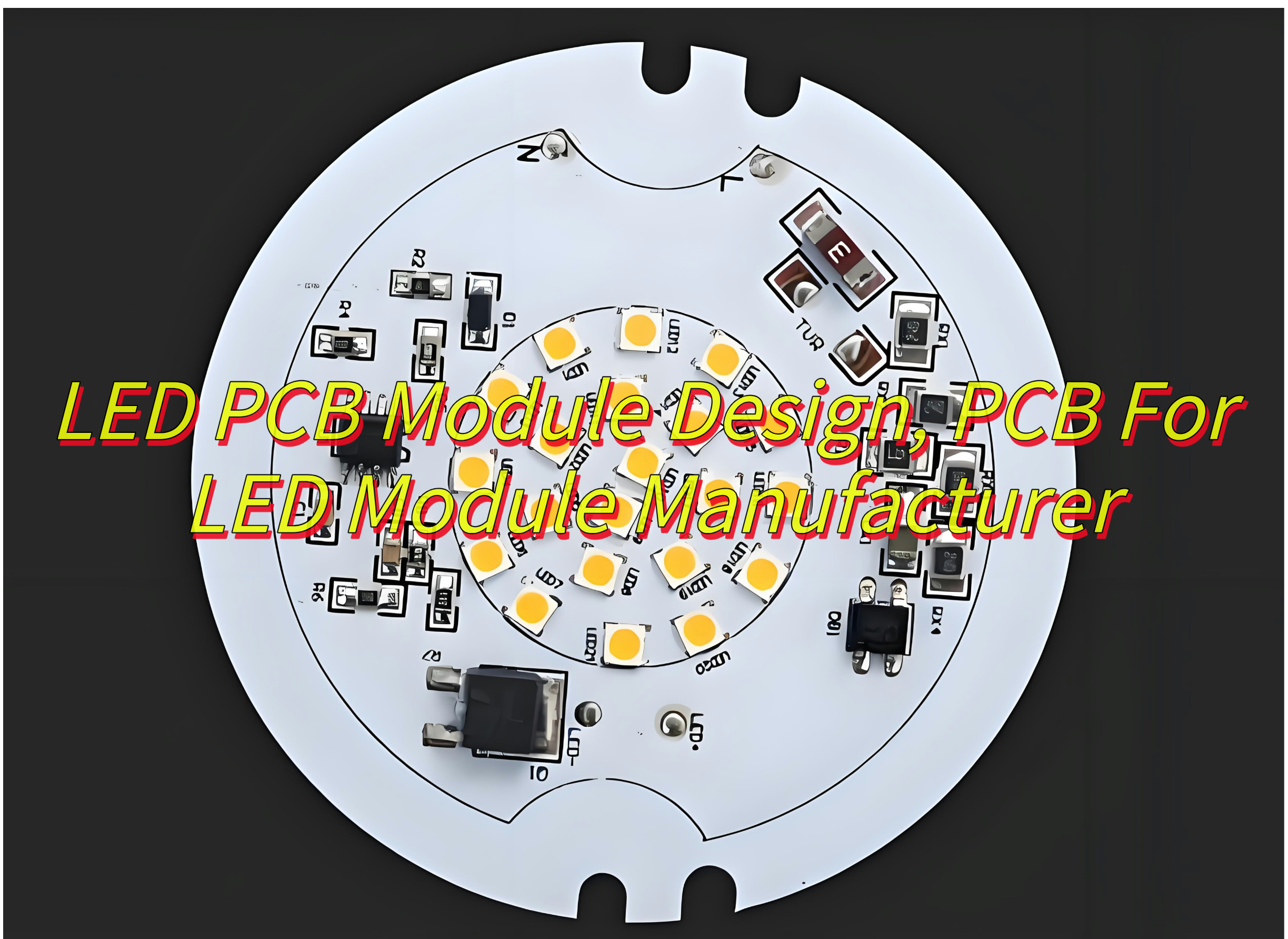
What Is LED PCB Module?
A LED PCB module integrates light-emitting diodes (LEDs) onto a printed circuit board (PCB) to form a complete lighting or display unit, combining electrical, thermal, and optical functions within a compact structure. These modules typically use materials like aluminum-core PCBs for efficient heat dissipation in high-power applications such as 20W LED board modules, ensuring stable performance and extended lifespan. Driverless LED PCB modules eliminate external power supplies by embedding current regulation directly into the circuit, simplifying installation in fixtures like 6W round bulb modules. Surface-mount device (SMD) technology enables precise placement of LEDs for uniform light distribution, while specialized designs for round PCB board LED modules address geometric constraints in space-limited applications. Thermal management remains a critical focus, with copper traces and dielectric layers optimized to prevent overheating in SMD LED PCB modules.
What Are Advantages of Driverless LED PCB Module?
- Simplified Circuitry Reduces Component Count
Driverless LED PCB modules eliminate the need for external drivers or complex circuitry. This streamlined design minimizes component failure risks, lowers assembly complexity, and shrinks the overall footprint. Fewer parts also mean reduced material costs and faster production timelines. - Enhanced Energy Efficiency
By removing power-consuming driver ICs, these modules achieve higher energy conversion rates. Direct AC or DC input ensures minimal power loss during transmission, making them ideal for battery-powered devices or solar-integrated systems where every watt counts. - Compact Design for Space-Critical Applications
The absence of bulky drivers allows for ultra-thin profiles. This makes driverless LED PCB modules perfect for slim lighting fixtures, wearable tech, or automotive interior panels where space is a premium. - Improved Thermal Performance
Fewer components generate less heat, while optimized copper traces on the PCB dissipate residual warmth efficiently. This dual benefit extends the module’s lifespan and maintains consistent light output even in high-temperature environments. - Cost-Effective Scalability
Manufacturers benefit from lower BOM costs and simplified inventory management. Driverless designs streamline production lines, reducing labor and testing expenses. These savings translate to competitive pricing for high-volume orders. - Direct Compatibility With Smart Systems
Driverless LED PCB modules integrate seamlessly with IoT platforms and dimming controls. Their plug-and-play nature simplifies retrofitting existing infrastructure with smart lighting solutions. - Reduced Electromagnetic Interference (EMI)
Fewer active components mean lower EMI emissions. This ensures compliance with global standards like FCC or CE, critical for medical devices or aviation lighting where signal integrity is non-negotiable. - Faster Time-to-Market
Simplified designs accelerate prototyping and certification processes. Manufacturers can iterate quickly, responding to market demands for custom shapes or wattages.

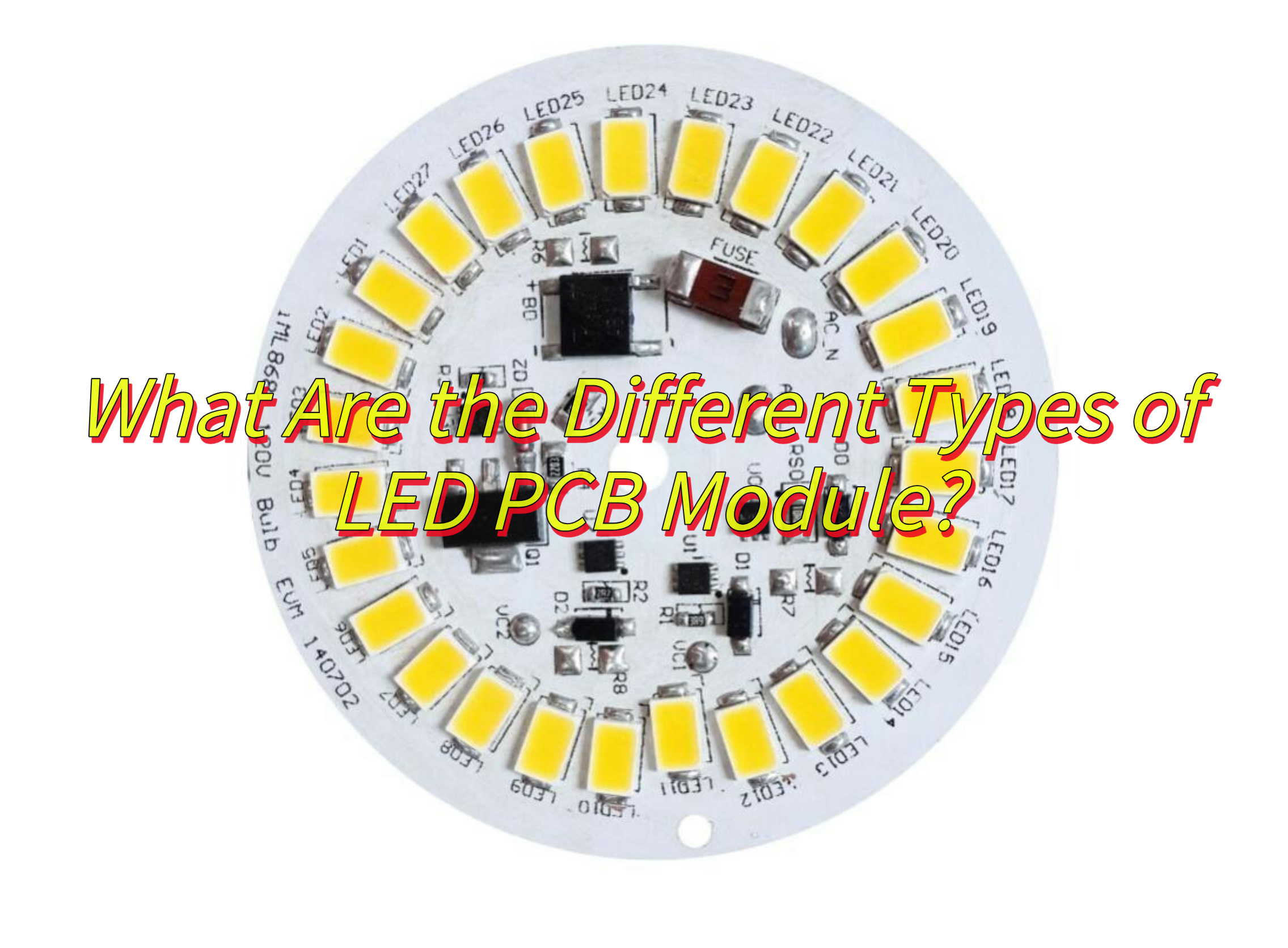
What Are the Different Types of LED PCB Module?
Below are types of LED PCB module:
1. By Packaging Technology
- Surface-Mounted Device (SMD) LED PCB Modules
LED chips are directly mounted on PCB surfaces via surface-mount technology. Features include rich color options, high brightness, and wide viewing angles. Commonly used in indoor lighting, displays, and commercial spaces like malls and conference halls. - Chip-on-Board (COB) LED PCB Modules
Multiple LED chips are bonded directly onto PCB substrates, forming high-density, high-luminance light sources. Suitable for commercial lighting, stage lighting, and applications requiring high light efficiency. - Dual In-Line Package (DIP) LED PCB Modules
LED components are inserted into PCBs via dual in-line pins, offering strong resistance to weather and high temperatures. Primarily used in outdoor billboards, stadiums, and harsh environments.
2. By Application Scenarios
- Indoor LED PCB Modules
Examples include SMD modules for malls and conference halls, prioritizing color accuracy and visual effects. - Outdoor LED PCB Modules
Such as DIP modules for billboards and stadiums, emphasizing waterproofing, dust resistance, and durability. - Specialized LED PCB Modules
Designed for automotive lighting, medical devices, and other niche applications, meeting stringent environmental and reliability demands.
3. By Material Properties
- Metal Substrate LED PCB Modules
Aluminum substrates excel in heat dissipation, ideal for high-power LED lighting to extend lifespan. - Flexible LED PCB Modules
Constructed on flexible substrates, enabling bending for cylindrical or curved displays. - Transparent LED PCB Modules
Transparent base materials with embedded LEDs achieve see-through displays for storefronts or architectural glass.
4. Other Specialized Types
- Smart LED PCB Modules
Integrate brightness and color temperature regulation for smart home or intelligent lighting systems. - High-CRI LED PCB Modules
Deliver natural-light-like color rendering, suitable for commercial spaces, museums, and galleries.
How to Design A SMD 6W Round LED Bulb PCB Module Board?
This is how to design a 6w SMD round LED bulb PCB module board:
1. Select SMD LED Components
- Choose high-efficacy LEDs (e.g., 130–150 lm/W) with compact footprints (e.g., 2835 or 3014 packages).
- Prioritize LEDs with built-in ESD protection and low thermal resistance (Rθ ≤ 8°C/W).
2. Design the PCB Layout
- Thermal Management: Use a 1.6mm aluminum-core PCB (MCPCB) with 2oz copper traces for heat dissipation.
- LED Arrangement: Place 6–8 LEDs in a radial pattern around the center to ensure uniform light distribution.
- Component Placement: Position electrolytic capacitors and drivers near the edge to minimize heat exposure.
3. Optimize Power Circuitry
- Implement a non-isolated buck converter with 90%+ efficiency to step down AC/DC input (85–265V) to 24–36V DC.
- Include a bleeder resistor to eliminate residual voltage and meet IEC 62471 photobiological safety standards.
4. Ensure Thermal Viability
- Calculate junction temperature using the formula: TJ = Ta + (Rθ × Pd). Aim for TJ ≤ 110°C.
- Add thermal via arrays under LED pads to conduct heat to the aluminum core.
5. Incorporate Dimming and Control Features
- Integrate a PWM dimming IC (e.g., BP5916) for 0–100% smooth dimming compatibility with TRIAC or 0–10V systems.
- Include surge protection (MOV) to withstand 4kV line transients.
6. Validate with Simulation Tools
- Use thermal simulation software to predict hotspots and adjust copper pours.
- Perform optical simulations to confirm beam angles (120°–180°) and luminance uniformity.
7. Prototyping and Testing
- Manufacture a prototype using ENIG surface finish for solderability.
- Conduct accelerated life testing (6000 hours at 85°C/85% RH) to validate L70 lifespan.
- Test flicker performance (<5% flicker index) per IEEE 1789 standards.
8. Industry Best Practices:
- A 2025 study by LED inside recommends MCPCBs with 3W/m·K thermal conductivity for 6W modules to maintain TJ below 105°C.
- Use conformal coating (e.g., acrylic resin) to protect against humidity in tropical climates.
How to Optimize Thermal Management in 20W LED PCB Board For Module?
Here is how to optimize thermal management in 20W LED PCB board modules:
Material Selection for Enhanced Thermal Conductivity
- Use metal-core PCBs (MCPCBs) with aluminum or copper substrates. Aluminum (1–3 W/m·K thermal conductivity) balances cost and performance, while copper (386 W/m·K) offers superior heat dissipation for high-power applications.
- Consider ceramic substrates (e.g., aluminum nitride, 170–220 W/m·K) for modules operating above 150°C, such as industrial UV curing systems.
Optimized PCB Layout and Component Placement
- Arrange LEDs in a radial or hexagonal pattern to distribute heat evenly and minimize thermal gradients.
- Isolate high-power components (e.g., MOSFETs, inductors) from LED arrays using thermal gaps or slit cuts in copper layers.
- Increase copper trace width to 20–30 mil for power lines to reduce resistance and heat buildup.
Advanced Thermal Via Design
- Implement staggered arrays of thermal vias (0.3–0.5mm diameter) beneath LED pads to conduct heat to inner layers or the substrate.
- Use via-in-pad technology to eliminate solder wicking and maximize thermal contact area.
Active and Passive Cooling Integration
- For 20W modules, combine a 25mm aluminum heat sink (finned design, 0.5mm pitch) with a 40×40mm axial fan to maintain junction temperature below 100°C.
- Apply graphene-enhanced thermal pads (8–12 W/m·K) between the PCB and heat sink to reduce interface thermal resistance by 40% compared to conventional silicone pads.
Thermal Simulation and Prototyping
- Conduct computational fluid dynamics (CFD) simulations using tools like 6SigmaET to model airflow and heat distribution. Validate with infrared thermography during prototyping.
- Perform accelerated thermal cycling (-40°C to 125°C, 1000 cycles) to identify solder joint fatigue risks.
Driver Circuitry Optimization
- Use a buck-boost converter with 95%+ efficiency to minimize power loss. Place the driver IC ≥10mm away from LEDs to prevent heat coupling.
- Include a soft-start circuit to limit inrush current and reduce transient thermal stress.
Environmental Protection Measures
- Apply conformal coating to protect against humidity and corrosion in outdoor applications. Ensure coating thickness ≤50µm to avoid compromising thermal performance.
- Incorporate a thermal shutdown circuit using an NTC thermistor to deactivate the module if Tj exceeds 120°C.
How to Select A Reliable PCB For LED Module Manufacturer?
Below is how to select a reliable PCB for LED module manufacturer:
Assess Rapid Prototyping Capabilities
- Confirm the manufacturer offers 24-hour turnaround for PCB samples using automated optical inspection (AOI) and electrical testing. Look for in-house engineering teams capable of adjusting designs within hours.
- Example: A 2025 case study shows manufacturers using LDI (Laser Direct Imaging) machines reduce prototype lead times by 60% compared to traditional photolithography.
Verify Flexible Production Lines
- Choose factories with modular SMT lines that switch between SMD, COB, or driverless LED PCB modules in under 2 hours. This adaptability supports low-volume custom orders (e.g., 50–500 units) without setup delays.
- Inquire about dual-track production for mixing high-volume (10,000+ units) and quick-turn orders without cross-contamination.
Evaluate Material Stock and Supplier Networks
- Ensure the manufacturer stocks FR-4, aluminum, and ceramic substrates for immediate use.
- Check for local component warehouses to avoid customs delays for LEDs, capacitors, and MOSFETs.
Review Customization Workflows
Confirm support for bespoke requirements such as:
- Ultra-thin PCBs (0.4mm–0.8mm thickness)
- Blind/buried vias for high-density LED arrays
- Immersion gold or ENEPIG finishes for gold wire bonding
Examine Quality Control for Speed and Accuracy
- Prioritize manufacturers with in-line AOI and SPI (Solder Paste Inspection) to catch defects before reflow. Automated systems reduce rework by 75% compared to manual checks.
- Request data on first-pass yield rates (FPY) for LED PCBs. Leading firms achieve ≥98.5% FPY through automated traceability systems linking each PCB to its test results.
Confirm Certifications and Compliance
- Ensure certifications like ISO 9001, ISO 14001, and UL for electrical safety. For automotive or medical LED modules, verify IATF 16949 or ISO 13485 compliance.
- Check for RoHS/REACH compliance and conflict-free mineral sourcing, critical for EU and North American markets.
Gauge Communication and Cultural Fit
- Select manufacturers with 24/7 multilingual support and project managers fluent in technical English. Delays often stem from miscommunication during DFM reviews.
- Use video calls to tour facilities and assess real-time order tracking systems that show WIP (Work-in-Progress) status and bottlenecks.
Compare Cost vs. Speed Trade-offs
- While 24-hour prototyping typically costs 30–50% more than standard lead times, negotiate volume discounts for repeat orders. Some firms waive NRE (Non-Recurring Engineering) fees for orders exceeding 5,000 units.
- Consider consignment production for urgent projects, where you supply critical components to bypass procurement delays.

How to Control the Quality of LED PCB Module Board Production?
This is how to control the quality of LED PCB module board production:
Implement Stringent Incoming Material Inspection
- Substrate Testing: Verify dielectric constant (Dk) and loss tangent (Df) of FR-4, aluminum, or ceramic substrates using a impedance analyzer. Reject batches with Dk variance >5%.
- Component Authentication: Use X-ray fluorescence (XRF) scanners to confirm lead-free (RoHS) compliance and counterfeit avoidance for LEDs, capacitors, and resistors.
Adopt Automated Optical Inspection (AOI) Post-SMT
- Deploy AOI machines with 12µm resolution to detect solder paste defects (e.g., bridging, insufficient), missing components, and polarity errors. Aim for <0.05% escape rate to downstream processes.
Conduct In-Circuit Testing (ICT) and Functional Testing
- Use flying probe testers for 100% electrical continuity checks on LED driver circuits. Validate current regulation (±5% tolerance) and thermal shutdown functionality.
- Perform photometric testing to confirm luminous flux, CCT, and CRI match design specifications.
Enforce Thermal Stress Testing
- Subject modules to 4 cycles of -40°C to 125°C with 15-minute dwell times. Reject units with delamination >0.1mm or LED binning shifts >1% in flux.
Implement X-ray Inspection for BGA/LGA Packages
- Use 3D X-ray systems to inspect solder joints under LED drivers and MOSFETs. Target voiding levels <10% for critical components.
Verify Conformal Coating Integrity
- Apply acrylic coatings (50–100µm thickness) and test with a corona discharge machine to ensure 100% coverage and dielectric strength >1.5kV.
Conduct Accelerated Life Testing (ALT)
- Run modules at TJ = 105°C for 1,000 hours while monitoring luminous decay. Reject batches with L70 (30% flux depreciation) <6,000 hours.
Audit Manufacturing Processes Regularly
- Use Statistical Process Control (SPC) charts to monitor solder paste printing, reflow oven profiles, and plasma cleaning efficiency. Investigate out-of-control points within 2 hours.
Certify Operators and Engineers
- Require IPC-A-610 certification for assembly technicians and J-STD-001 expertise for soldering supervisors. Conduct biannual skills assessments.
Maintain Traceability via QR Codes/Data Matrices
- Laser-etch unique IDs on each PCB linking to a database storing material lot numbers, process parameters, and test results. Enable 48-hour root-cause analysis for failures.
Can You Custom LED PCB For Special Module Design?
Yes, custom LED PCB can be designed for special module requirements, offering tailored solutions to meet unique performance, form factor, and environmental needs. Manufacturers can produce LED PCBs in non-standard shapes using precision cutting technologies, integrate advanced materials like ceramic substrates for high-temperature applications, and embed thermal management innovations such as micro heat pipes or liquid cooling channels. Optical performance can be enhanced through lens array integration and custom phosphor blends, while electrical integration includes embedded drivers and smart controls for IoT connectivity. Environmental adaptations range from conformal coatings for marine environments to aerospace-grade PCBs withstanding extreme conditions. Rapid prototyping within 24 hours and low-volume production without NRE fees support agile development, and rigorous quality assurance ensures reliability. For instance, a 2025 medical lighting project utilized a 12W circular PCB with 24 bi-color LEDs, achieving 98 CRI and a 50,000-hour lifespan through ceramic substrates and phosphor engineering. Such customization drives innovation in specialized fields, ensuring modules exceed off-the-shelf solutions in performance and longevity.