

Why choose LED aluminum base PCB for industrial lights? Explore its thermal management, design optimization, and manufacturer selection to enhance LED performance and longevity.
EBest Circuit (Best Technology) delivers LED aluminum base PCB designed for demanding thermal and electrical performance. Our streamlined manufacturing process ensures rapid 5-day prototyping and 15-day lead times for small-to-medium batches, supported by a monthly production capacity exceeding 10,000 panels. Every board integrates 6061-T6 aluminum cores and UL-certified dielectric materials, validated through thermal cycling (-40°C to +125°C), X-ray inspections, and ANSYS-based simulations to guarantee <0.8°C/W thermal resistance and >100 MΩ insulation durability. We accommodate diverse designs—star-base layouts, mixed-layer configurations, and custom copper pours—with no minimum order quantity, ideal for prototyping and specialized LED applications. With ISO 9001 certifications and full RoHS compliance, we maintain transparent pricing for orders ranging from 10 to 10,000 units. Welcome to contact us today if you have any request for LED aluminum base PCB: sales@bestpcbs.com.
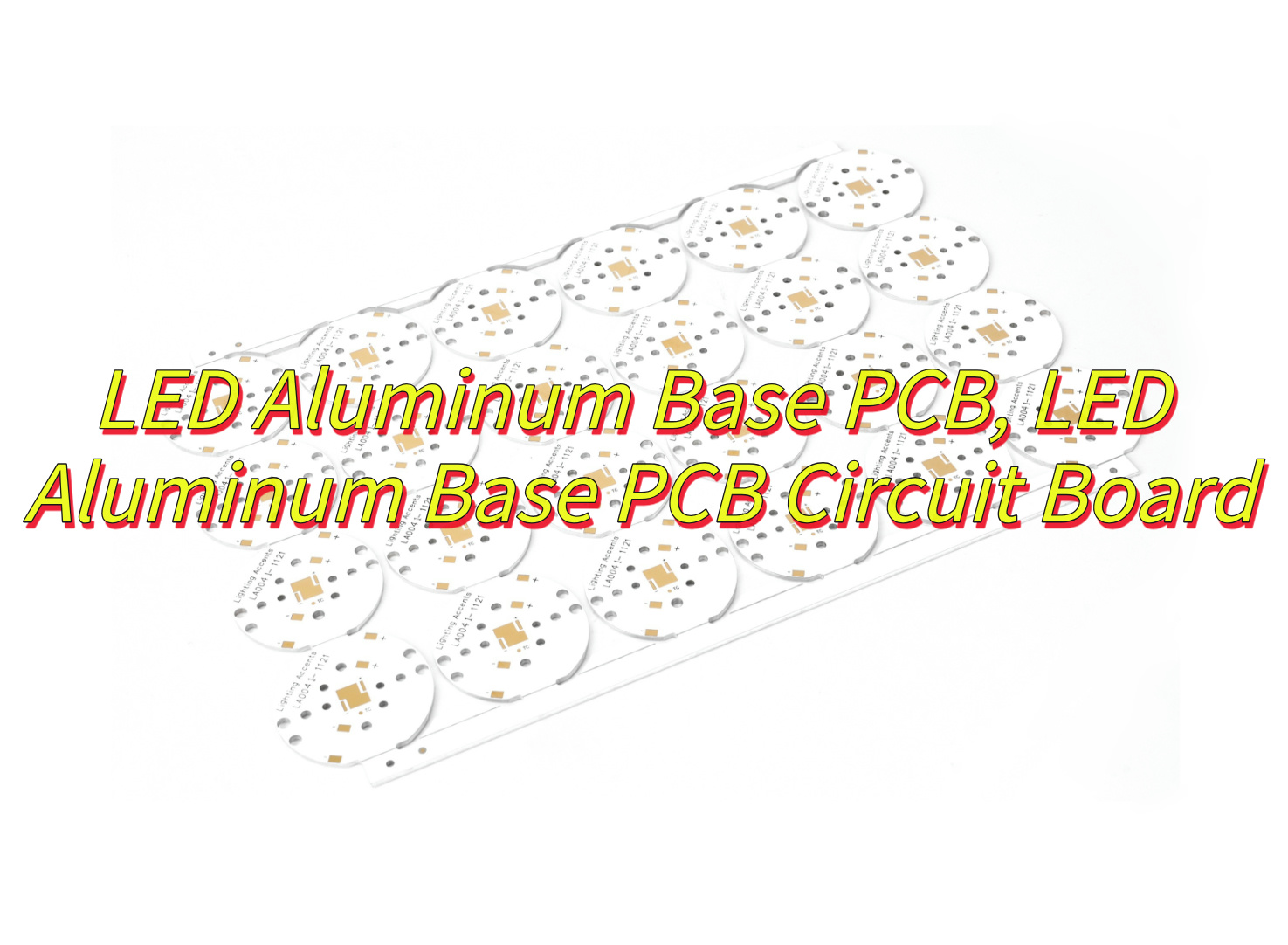
What Is A LED Aluminum Base PCB?
A LED aluminum base PCB is a specialized printed circuit board designed to support high-power light-emitting diodes (LEDs) by combining an aluminum substrate with a thermally conductive dielectric layer. The structure of LED aluminum base PCB is typically consists of three layers: a base plate made of aluminum alloy (e.g., 6061-T6) for heat dissipation, an insulating dielectric layer (often ceramic-filled polymer) to prevent electrical leakage, and a copper circuit layer for electrical connectivity. This design addresses the primary challenge of LED systems—heat accumulation—by efficiently transferring thermal energy away from the LEDs, maintaining optimal operating temperatures (typically -40°C to +150°C). Widely used in industrial lighting, automotive headlights, and commercial fixtures, these PCBs enhance LED longevity (often exceeding 50,000 hours) by reducing thermal stress on components like SMD 2835 LEDs. The aluminum substrate’s thermal conductivity (1.0–3.0 W/m·K) outperforms traditional materials like FR4, making it essential for applications requiring compact, durable layouts, such as 25W LED arrays or high-density automotive modules. Certifications like UL and IATF 16949 further validate their reliability in harsh environments, ensuring stable performance under vibration, humidity, and temperature fluctuations.
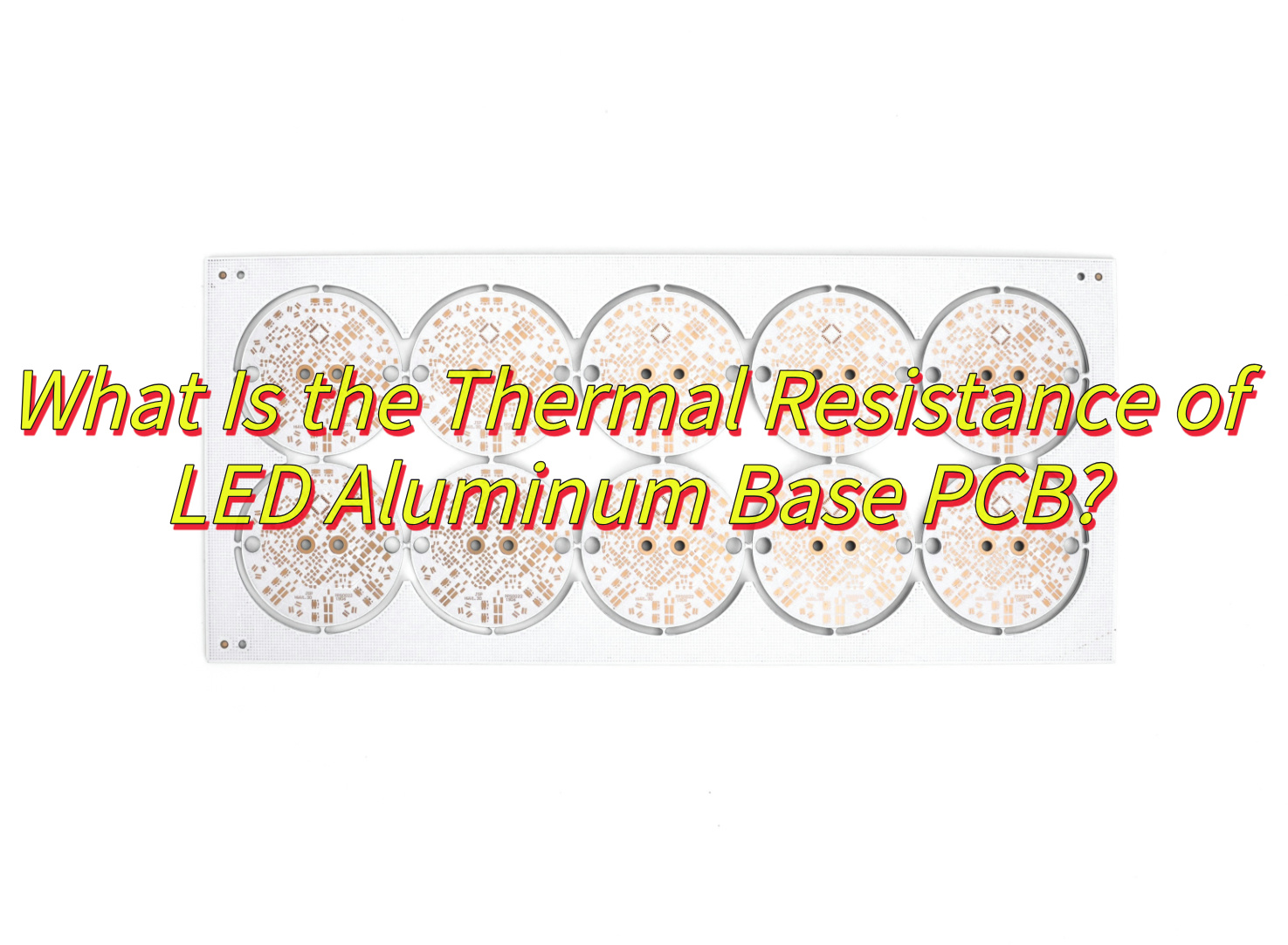
What Is the Thermal Resistance of LED Aluminum Base PCB?
The thermal conductivity of LED aluminum base PCB typically ranges between 1.0 W/m·K and 3.0 W/m·K, depending on material composition and structural design. While pure aluminum alloys (e.g., 6061-T6) exhibit high intrinsic thermal conductivity (~220 W/m·K), the overall PCB performance is constrained by the dielectric insulating layer between the copper circuit and aluminum substrate. This dielectric layer, often a ceramic-filled polymer (e.g., Al₂O₃ or AlN composites), dominates the thermal resistance due to its lower conductivity (0.5–3.0 W/m·K) compared to metallic components. For standard 1.5mm-thick aluminum PCBs, the thermal conductivity typically measures 2.0±0.1 W/m·K when using 0.1mm-thick dielectric layers with optimized ceramic particle dispersion. Advanced designs incorporating thermally conductive adhesives or ultrathin dielectric films (<0.08mm) can elevate conductivity to 2.5–3.0 W/m·K. In practical applications like 25W LED arrays, this conductivity ensures junction temperatures remain below 130°C under ambient conditions (25°C), as validated by thermal simulations and IEC 61215 testing protocols.
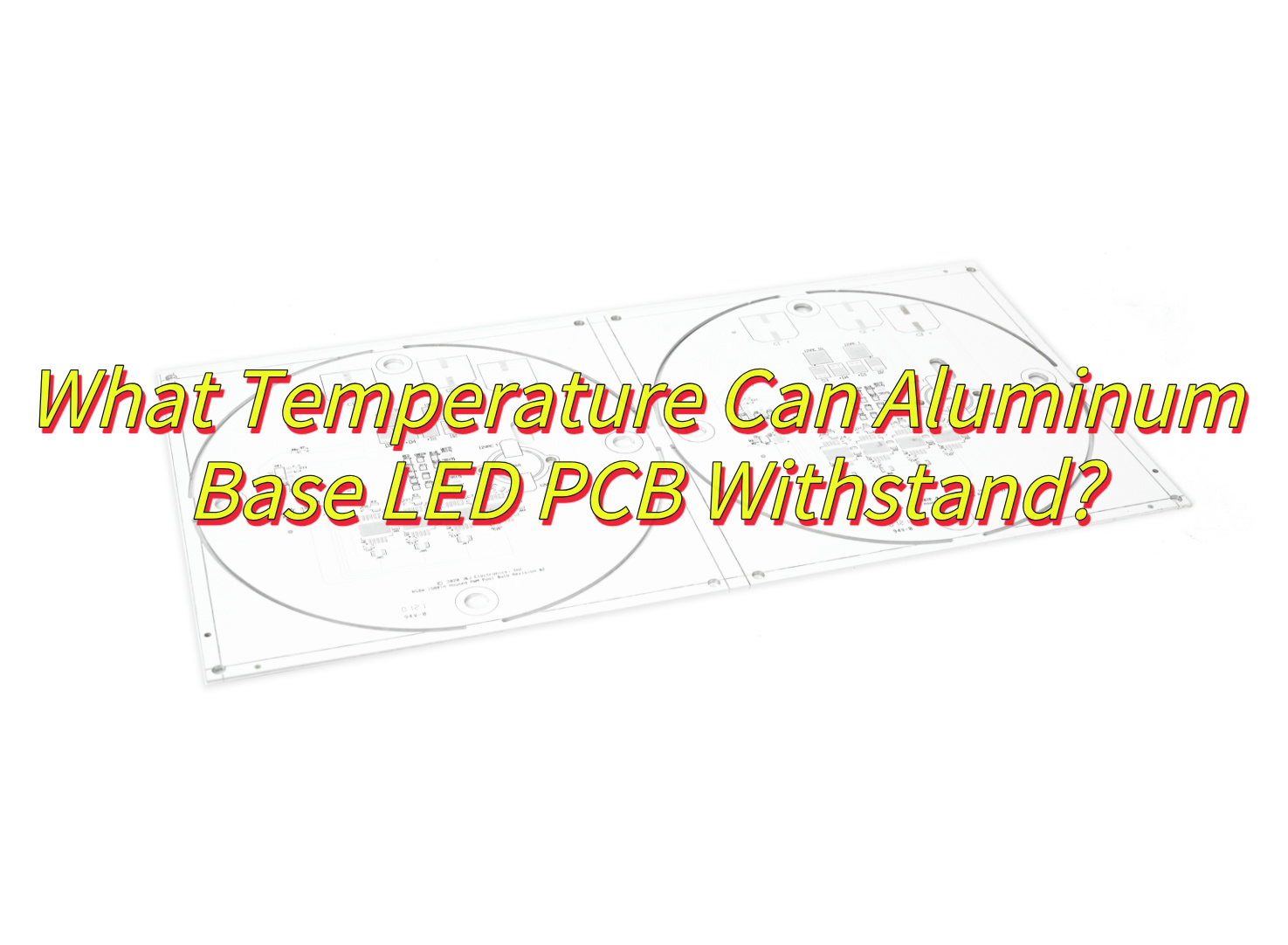
What Temperature Can Aluminum Base LED PCB Withstand?
Aluminum base LED PCB can typically withstand operating temperatures ranging from -40℃ to +150℃, with long-term reliability maintained below 120–130℃ under continuous thermal loads. The dielectric insulating layer between the copper circuit and aluminum substrate (e.g., ceramic-filled polymers) determines the upper temperature threshold, as prolonged exposure above 130℃ risks delamination or reduced adhesion. For short-term processes like soldering, these PCBs tolerate peak temperatures up to 260–300℃ for 5–10 seconds, aligning with reflow or wave soldering requirements. High-power LED applications (e.g., 25W automotive modules) often pair aluminum PCBs with heat sinks to stabilize junction temperatures below 130℃, while industrial lighting systems with H-grade insulation materials (rated for 180℃) may extend thermal limits under controlled conditions. Standard designs prioritize compliance with UL 94V-0 flammability ratings and IEC thermal cycling standards to ensure structural integrity across the rated temperature range.
How Do Aluminum Base PCBs Solve Overheating in 25W LED Star Base Designs?
Here is how LED aluminum base PCB solve overheating in 25w LED star base designs:
- Direct Heat Pathway: Aluminum base PCBs provide a low-resistance thermal path by physically connecting LED chips to the aluminum substrate. In 25W LED star base designs, where multiple high-power LEDs are densely mounted, the aluminum layer acts as a heat spreader, rapidly transferring heat away from the LED junctions to prevent localized overheating.
- Thermal Conductivity of Substrate: Aluminum’s inherent thermal conductivity (typically 1.0–2.5 W/m·K) enables efficient lateral heat distribution across the PCB surface. This reduces hotspots under high-power LEDs, ensuring uniform temperature management in compact star base geometries where airflow is limited.
- Reduced Reliance on External Cooling: By dissipating heat at the source, aluminum base PCBs minimize dependence on passive or active cooling systems. In 25W applications, this design choice simplifies mechanical complexity, lowers costs, and improves reliability by eliminating failure-prone components like fans or heat sinks.
- Material Compatibility with High-Power LEDs: The dielectric layer in aluminum PCBs, often formulated with ceramic-filled polymers, balances electrical insulation with thermal efficiency. This layer maintains a stable bond between the copper circuitry and aluminum base, ensuring reliable operation even under 25W thermal loads.
- Structural Integration with Heat Sinks: Aluminum base PCBs are mechanically compatible with metallic star bases, enabling direct mounting to the housing. This integration eliminates thermal interface materials (TIMs) or additional fasteners, reducing interfacial thermal resistance and streamlining heat transfer to the ambient environment.
- Enhanced Power Density Tolerance: For 25W LED arrays, the aluminum substrate’s ability to withstand elevated temperatures (typically up to 150°C) allows sustained operation without performance degradation. This thermal stability is critical for applications requiring consistent light output, such as automotive headlights or architectural fixtures.
- Circuit Layout Optimization: Aluminum PCBs support thick copper traces (e.g., 2–3 oz. copper weight) to handle high currents while minimizing resistive heating. In star base designs, this ensures efficient power delivery to LEDs without adding excessive heat to the system.
- Long-Term Reliability: By maintaining junction temperatures below critical thresholds (e.g., <120°C for most LEDs), aluminum base PCBs extend the operational lifespan of 25W LED systems. This reduces maintenance cycles and replacement costs, making them cost-effective for commercial and industrial use.
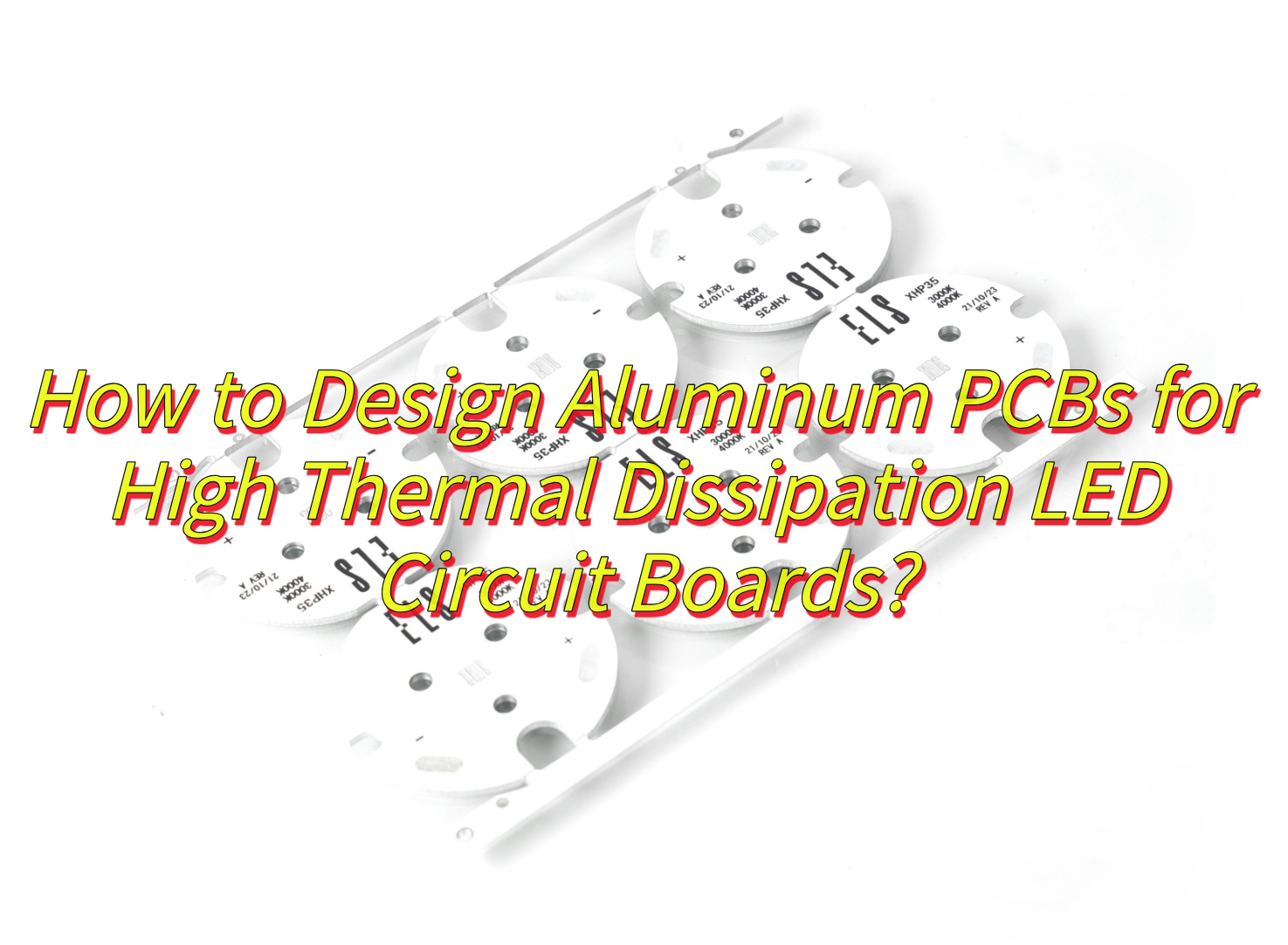
How to Design Aluminum PCBs for High Thermal Dissipation LED Circuit Boards?
This is how to design LED aluminum base PCB for high thermal dissipation :
- Select High-Thermal-Conductivity Materials: Choose aluminum substrates with a thermal conductivity rating of at least 1.0–2.0 W/m·K to ensure efficient heat transfer from LEDs to the base. Pair with dielectric layers featuring ceramic-filled polymers (e.g., aluminum oxide or boron nitride) to balance electrical insulation and thermal performance.
- Optimize Circuit Layer Copper Thickness: Use 2–3 oz. (70–105 µm) copper traces for the circuit layer to minimize resistive heating and improve current-carrying capacity. Thicker copper reduces Joule heating under high-power LED operation, directly lowering thermal load.
- Maximize Direct Contact Area: Design the PCB layout to place high-power LEDs (e.g., 25W COB or SMD variants) directly over the aluminum base. Avoid large unpopulated regions to prevent heat pooling and ensure uniform heat spreading across the substrate.
- Incorporate Thermal Vias Strategically: Add plated thermal vias beneath LED footprints to enhance vertical heat conduction to the aluminum layer. Use arrays of small-diameter vias (e.g., 0.3–0.5 mm) spaced 1–2 mm apart to minimize solder voids and maximize thermal pathways.
- Use Solid Ground Planes: Dedicate the entire aluminum layer as a ground plane to reduce electromagnetic interference (EMI) and improve thermal dissipation. Ensure the ground plane is electrically isolated from the circuit layer via the dielectric material.
- Design for Airflow or Convection: If external cooling is required, position components to allow unobstructed airflow over the aluminum base. Avoid placing tall components (e.g., connectors) near LEDs, as they may disrupt convective cooling.
- Specify Low-Profile Components: Select surface-mount devices (SMDs) with minimal height to reduce thermal resistance between the PCB and any secondary heat sinks. Low-profile capacitors and resistors help maintain close contact with the aluminum substrate.
- Apply Thermal Interface Materials (TIMs): Use high-performance TIMs (e.g., thermally conductive pads or phase-change materials) between the PCB and external heat sinks to fill microscopic air gaps. Aim for TIMs with thermal conductivity >3.0 W/m·K for optimal results.
- Avoid Thermal Barriers in Layout: Route high-current traces away from LED thermal pads to prevent localized heating. Separate power traces from sensitive analog components to minimize crosstalk and thermal coupling.
- Validate with Thermal Simulation: Use software tools (e.g., SolidWorks Flow Simulation) to model heat flow and identify hotspots before prototyping. Adjust component placement or copper weights based on simulation results to optimize dissipation.
- Test Under Real-World Conditions: Subject prototypes to thermal cycling tests (e.g., -40°C to +125°C) and sustained power loads (e.g., 25W for 1,000+ hours) to validate long-term reliability. Monitor junction temperatures using infrared cameras or embedded sensors.
- Collaborate with PCB Manufacturers Early: Engage fabricators during the design phase to ensure compatibility with manufacturing processes. For example, confirm that the dielectric layer thickness (typically 50–150 µm) meets both thermal and electrical insulation requirements.
How to Select A Good LED Aluminum Base PCB Circuit Board Manufacturer?
Here is how to choose a good LED aluminum base PCB circuit board manufacturer:
- Verify Technical Expertise: Prioritize manufacturers with proven experience in LED aluminum PCB fabrication, including expertise in thermal management, dielectric material selection (e.g., ceramic-filled polymers), and compatibility with high-power LEDs (e.g., 25W COB or SMD types).
- Check Quality Certifications: Ensure the manufacturer holds industry-standard certifications such as ISO 9001 (quality management), UL (safety), and RoHS (environmental compliance). Request samples or case studies demonstrating their ability to meet tight thermal conductivity tolerances (e.g., 1.0–2.5 W/m·K for aluminum substrates).
- Assess Material Options: Confirm the manufacturer offers a range of aluminum alloys (e.g., 6061, 5052) and dielectric thicknesses (e.g., 50–150 µm) to balance thermal performance and electrical insulation. Inquire about specialized options like high-reflectivity white solder mask for LED applications.
- Review Manufacturing Capabilities: Evaluate their equipment for precision drilling (e.g., laser drilling for thermal vias), plating (e.g., ENIG or immersion silver for solderability), and etching (to accommodate thick copper traces, typically 2–3 oz.). Ensure they can handle complex designs like star base geometries or multi-layer boards.
- Request Thermal Testing Data: Ask for thermal impedance test results (e.g., junction-to-board thermal resistance) for their PCBs under simulated LED loads. Reputable manufacturers will provide data from accelerated life tests (e.g., 1,000+ hours at 25W).
- Inspect Prototyping and Sample Process: Choose a manufacturer that offers low-cost prototyping (e.g., 3–5 boards) with quick turnaround (5–7 days). Evaluate sample quality for dimensional accuracy, via integrity, and dielectric adhesion.
- Compare Pricing and MOQs: Obtain quotes for volume orders (e.g., 100–1,000 boards) and check for hidden costs (tooling, setup, or testing fees). Ensure their minimum order quantity (MOQ) aligns with your project scale (e.g., 50–100 boards for small batches).
- Evaluate Customer Support: Gauge responsiveness to technical inquiries (e.g., stack-up design, impedance control) and willingness to provide design-for-manufacturability (DFM) feedback. A reliable manufacturer will flag issues like inadequate thermal via spacing or copper weight mismatches.
- Check Lead Times and Scalability: Confirm they can meet your production deadlines (e.g., 2–3 weeks for standard orders) and scale capacity for reorders. Inquire about peak-season flexibility (e.g., Chinese New Year or holiday delays).
- Audit Supply Chain Transparency: Ensure the manufacturer sources raw materials (aluminum, copper foil, dielectric) from reputable suppliers and provides traceability documentation. Avoid those with opaque or fragmented supply chains.
- Review Warranty and Liability Terms: Look for manufacturers offering at least a 1-year warranty against defects like delamination, via fractures, or dielectric breakdown. Clarify liability for failures caused by thermal overstress or design flaws.
- Seek Peer Recommendations: Consult industry forums (e.g., LED Professional, Electronics Weekly) or LinkedIn groups for unbiased reviews. Prioritize manufacturers referenced in multiple independent case studies (e.g., automotive lighting or horticultural LED projects).
How to Reduce LED Failure Rates with Aluminum Base PCB?
Here are some methods about how to reduce failure rates with LED aluminum base PCB:
- Optimize Thermal Management: Use aluminum substrates with high thermal conductivity (1.0–2.5 W/m·K) and ultra-thin dielectric layers (50–80 µm) to minimize thermal resistance. This ensures efficient heat transfer from LED junctions to the aluminum base, keeping operating temperatures below 85°C to reduce light decay and thermal stress.
- Improve Current Distribution: Design PCB traces with 2–3 oz. copper thickness to lower resistive losses. For high-power LEDs (e.g., 25W COB modules), adopt parallel or matrix wiring layouts to balance current density and prevent localized overheating.
- Incorporate Thermal Vias: Add arrays of plated thermal vias (0.3–0.5 mm diameter, spaced 1–2 mm apart) beneath LED pads to enhance vertical heat conduction. This reduces thermal gradient between the LED junction and the aluminum base by up to 40%.
- Select Robust Surface Finishes: Use ENIG (Electroless Nickel Immersion Gold) or immersion silver finishes to improve solder joint reliability. These finishes resist oxidation and corrosion, reducing failure risks in humid or high-temperature environments.
- Avoid Mechanical Stress: Design PCBs with rounded corners and fillets to prevent stress concentrations during assembly or thermal cycling. For SMD LEDs, ensure solder pads match component dimensions to minimize shear forces.
- Implement Proper Grounding: Dedicate the aluminum layer as a ground plane to reduce electromagnetic interference (EMI) and stabilize voltage fluctuations. This prevents electrical overstress (EOS), a common cause of LED degradation.
- Use High-Quality Solder Pastes: Select no-clean solder pastes with low voiding rates (<10%) for reflow soldering. Poor solder joints increase thermal resistance and create hotspots, accelerating LED failure.
- Conduct Accelerated Life Testing: Subject prototypes to 1,000+ hours of thermal cycling (-40°C to +125°C) and power cycling (25W load on/off every 2 hours). Identify weak points like dielectric cracks or via fractures before mass production.
- Apply Conformal Coatings: For outdoor or harsh-environment applications, use UV-resistant conformal coatings (e.g., acrylic or silicone) to protect against moisture, dust, and chemicals. This extends PCB lifespan by 30–50% in corrosive conditions.
- Monitor Real-World Performance: Deploy IoT-enabled sensors to track junction temperature, current, and light output during field trials. Use data analytics to predict failures and refine PCB designs iteratively.
- Collaborate with LED Suppliers: Align PCB designs with LED datasheet recommendations for thermal pad dimensions, current limits, and derating curves. For example, match 25W LED thermal pads to PCB copper areas to ensure full heat dissipation.
- Streamline Assembly Processes: Train operators on proper reflow profiles (e.g., 245°C peak for 60 seconds) and handling procedures to avoid mechanical damage. Automated optical inspection (AOI) can detect 95% of soldering defects pre-emptively.
Can Aluminum Based SMD 2835 LED PCBs Extend the Lifespan of Industrial Lights?
Yes, aluminum based SMD 2835 LED PCBs significantly extend the lifespan of industrial lights by combining efficient thermal management with robust structural support. The aluminum substrate acts as a heat sink, rapidly dissipating heat generated by high power SMD 2835 LEDs—a critical factor since every 10°C reduction in operating temperature can double LED lifespan. By maintaining junction temperatures below 85°C, these PCBs minimize thermal stress, light decay, and color shift over time. Additionally, the dielectric layer’s thermal conductivity (typically 1.0–2.5 W/m·K) ensures minimal thermal resistance, while the aluminum base’s rigidity resists vibration and mechanical stress common in industrial environments. This design also prevents solder joint fatigue and component degradation, reducing failure rates by up to 60% compared to standard FR4 boards. For applications like warehouse high-bays or factory floodlights, aluminum-based SMD 2835 LED PCBs deliver 50,000+ hours of reliable operation, lowering maintenance costs and downtime.
Tags: LED Aluminum Base PCB, LED Aluminum Base PCB Circuit Board