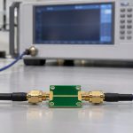
If a passive PCB coupon expected to be reciprocal gives you different S21 and S12, compare the complex transmission coefficients, not just the two dB traces. Then put a known reciprocal verification device at the same calibration planes and measure it in both directions. If the reference shows the same mismatch, fix the setup before blaming the board. If the VNA agrees but the exported file does not, inspect the file and processing chain before measuring again.
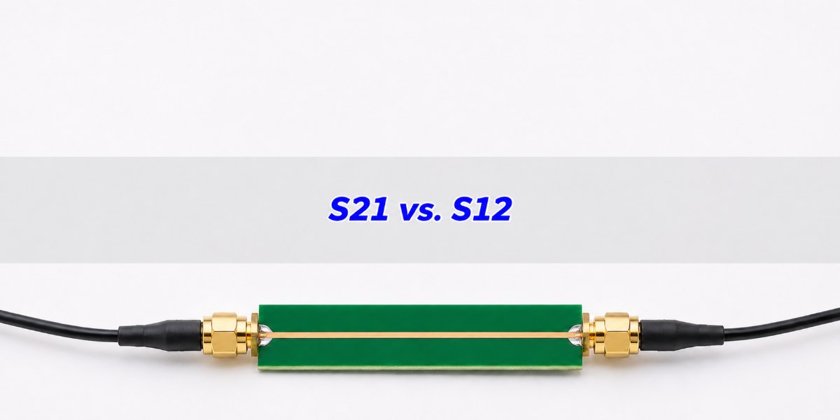
S21 vs. S12: Which Direction Is Each Trace?
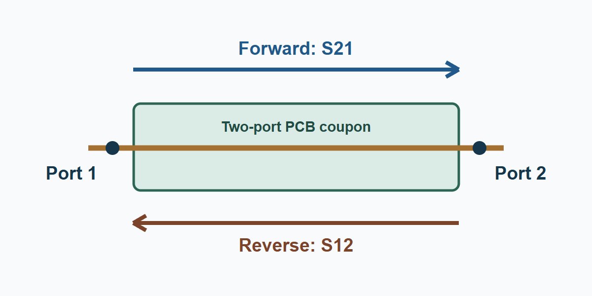
The first index is the response port; the second is the driven port. S21 is the outgoing wave at port 2 divided by the incident wave at port 1, with no incident wave from port 2. S12 reverses the drive and response with the same port numbers. The other port is terminated in the measurement reference impedance for the coefficient definition. Changing the drive direction does not mean renumbering the connectors on the board.
Both coefficients have magnitude and phase. Displaying 20 log10 of their magnitudes answers how much the signal is attenuated or amplified, not whether their complex values agree. Keep a port map showing the board end, cable and VNA port so another engineer can reproduce the setup after a reconnect.
Reciprocal Network: What Should and Should Not Match?
For an ordinary reciprocal two-port measured with equal real reference impedances and consistent power-wave normalization, S21 = S12 at the same frequency and reference planes. This is equality of the full complex values. The two reflections, S11 and S22, need not match: a board can have a different connector launch on each end and still transmit reciprocally. For a compatible multiport basis, the comparison is against the plain matrix transpose, not its complex conjugate.
Reciprocity is separate from passivity. A correctly specified ferrite isolator, for example, can be passive while intentionally attenuating reverse transmission more than forward transmission. A biased active stage can also be direction-dependent. Check the intended function, terminations, bias and power setting before applying a reciprocal-coupon release rule. Use the S-parameter passivity check separately if the model must also satisfy a passive power bound.
S21 and S12: Equal dB Can Still Hide a Phase Error
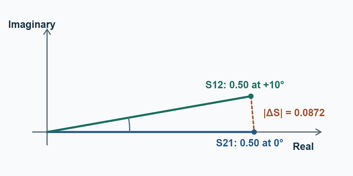
Illustrative values at 5 GHz: S21 = 0.50 at 0° and S12 = 0.50 at +10°. Both magnitude readings are −6.02 dB. In rectangular form, S21 is 0.5000 + j0 and S12 is about 0.4924 + j0.0868. Their complex difference has magnitude 0.0872. If you subtract only their dB values, you find zero and miss the disagreement.
Plot the absolute residual |S21 − S12| versus frequency using linear complex values. For two equal magnitudes A and phase difference Δφ its value is 2A × |sin(Δφ/2)|. Do not use a large phase swing at a very small signal level as stand-alone evidence; first establish that both measurements are above the usable noise and leakage limits. The residual is dimensionless, not dB.
VNA Calibration: Verify Forward and Reverse Before Reconnecting
- State the reference planes. Record cable orientation, adapters, fixture, connector condition, calibration method, sweep grid, source power and IF bandwidth. Use an applicable full two-port correction at the agreed planes, such as SOLT for appropriate coaxial standards or a qualified TRL setup for a fixture.
- Measure an independent reciprocal reference at those planes. An appropriate verification thru, line or attenuator should be independent of the solve and suit the band and loss of interest. A low-loss thru alone does not qualify a deep stopband. Record both phase and magnitude.
- Repeat the DUT without an avoidable setup change. First capture both VNA directions without physically swapping the cables. If a reversal check is needed, keep the calibrated cables and adapters fixed as far as practical, document which board end goes to which port, and recheck the reference after reconnecting. Do not interpret a reversed setup as a clean confirmation if a cable had to move substantially.
Keysight describes distinct forward and reverse terms in full two-port error correction. A good trace in one direction does not validate the other. A mismatch that appears on the reference is a reason to check the instrument path, not proof that a particular receiver or switch failed.
VNA Dynamic Range: Find Where the Comparison Stops Being Useful
In a deep stopband, the reverse trace may be dominated by instrument noise or residual leakage rather than transmission through the filter. Check a suitable terminated or isolated reference under the same sweep settings, then repeat both traces at a verified lower IF bandwidth. Noise can decrease while systematic leakage stays. If either direction remains too close to the established floor, flag the band as inconclusive rather than publishing a direction-specific isolation number.
If a stable residual remains after the noise check, use the VNA isolation calibration guide to decide whether to use the optional correction and verify it against an independent attenuator before comparing the two directions.
| Observed pattern | Next discriminating check | Decision |
|---|---|---|
| Same dB, phase split in the passband | Compare raw complex traces with an independent reciprocal reference at unchanged planes. | If the reference shows the split, requalify the setup; do not reject the PCB. |
| Difference mainly near the stopband floor | Check residual leakage and repeat both directions with verified measurement settings. | If acceptable uncertainty cannot be shown, report the band as inconclusive. |
| Raw traces agree; processed file does not | Re-import the raw export, then apply reference corrections and transforms one step at a time. | Fix the step that introduced the mismatch rather than hiding it by copying a column. |
| Difference persists with a clean reference | Check expected directionality, fixture removal, port maps and stimulus-dependent behavior; repeat independently. | Escalate before declaring nonreciprocity on an ordinary PCB coupon. |
Touchstone File: Compare Each Processing Stage
Save the instrument traces and the untouched file before renormalization, de-embedding, port extension or mixed-mode conversion. Check the frequency units, data format (RI, MA or DB), port map and real reference resistance. In conventional two-port Version 1 data the file lists S11, S21, S12, S22. Touchstone 2.1 allows an explicit [Two-Port Data Order]. Read it rather than imposing an order. Check [Matrix Format] too: a triangular file format can encode assumed symmetry and cannot independently prove that both directions were measured.
Re-import with a compatible reader and compare known complex samples against the instrument first. Then replay each processing step. A plain exchange of S21 and S12 by itself changes the sign of S21 − S12 but not its magnitude; a new nonzero residual points to another mismatch, such as a wrong column, inconsistent reference correction, grid alignment, or asymmetric processing. Never replace the reverse trace with the forward trace to make an undiagnosed problem vanish.
S-Parameter Reciprocity in Three PCB Measurement Tasks
PCB interconnect coupon
Use the raw two-direction data to qualify a passive trace and its launches. For a representative verification condition, compare trace residual over the required band and recheck the references if the ports have been disturbed. Release only if the residual meets the agreed data-quality limit and the coupon meets its own insertion-loss and reflection requirements. Different S11 and S22 can still matter to the system even if reciprocity passes.
RF filter on an assembled board
Compare the two transmission directions in the passband and establish usable measurement range in the stopband. Keep fixture terminations and any bias networks in the defined configuration. Report measurable bands separately from floor-limited bands; do not accept a stopband number simply because forward and reverse both look flat at the instrument floor.
PCB with an isolator or active RF chain
The design may intentionally have unequal transmissions. Verify the expected forward direction and reverse isolation against its specification at the specified bias, power and termination. Reversing a connectorized fixture still requires a defined port map. For a three-port device report the unused-port termination and do not infer the complete multiport behavior from a two-port subset.
VNA Measurement Uncertainty: What Goes in the Release Report?
Use this worksheet to review a new S2P file. The test plan must define frequency bands, expected network class, reporting metric, validation reference and evidence for the decision limit. A set of repeat sweeps estimates repeatability but does not by itself bound systematic errors. Have the lab include validated calibration, fixture, dynamic-range and reference-check contributions appropriate to the band.
| Required evidence | What to record | If missing |
|---|---|---|
| Comparable data | Port mapping, same planes, impedances, operating state and frequency grid; two measured directions. | Hold the comparison. A symmetrical export is not independent evidence. |
| Uncertainty and usable band | Calibration and independent checks, residual repeatability, receiver limits and decision rule. | Flag measurements outside the validated band or level as inconclusive. |
| Illustrative decision at 5 GHz | |S21 − S12| = 0.0872; assume a project-specific review trigger of 0.0200 for this example. | 0.0872 exceeds 0.0200. Hold the file and localize the cause; this alone does not establish a faulty PCB. |
The example trigger is not an IPC threshold or an instrument specification. If the report cannot show how the setup supports a limit, request the missing evidence before qualifying the file or changing the fixture.
S21 vs. S12 FAQs
Do S21 and S12 have to be the same on every passive PCB?
No. Confirm the network is expected to be reciprocal and the two measurements have comparable references. A passive isolator is a counterexample.
Can S11 and S22 differ on a reciprocal board?
Yes. Reciprocity relates exchanged transmission terms. Different launches or impedances at the two ends can give different reflections.
Why can the two traces match in dB but disagree in the file?
A dB plot omits phase. Compare the real and imaginary components, or reconstruct them from magnitude and phase before subtracting.
Does swapping the two VNA cables prove the PCB is directional?
No. You may also change cable shape, contact repeatability or calibration planes. Keep a board-end map and verify the calibrated paths.
Can a lower IF bandwidth fix S21 and S12 disagreement?
It can reduce random receiver noise. It does not undo a wrong reference plane, fixture model, or stable leakage path.
Can I use a reciprocal thru to validate reverse isolation?
A thru is a useful basic check but normally does not establish the uncertainty at the much lower transmission level of an isolation measurement.
Does a symmetric Touchstone file prove the two directions were measured?
No. A reader can fill missing entries from triangular storage. Ask for the measured full two-direction data and the export settings.
Should I average S21 and S12 to repair a file?
Keep the raw data independent. Use symmetry constraints only as a documented model decision after establishing that the network is reciprocal and understanding the original discrepancy.
Technical References
- Rohde & Schwarz: Understanding S-parameters — coefficient definitions and complex data.
- Keysight: Full 2-Port Calibration — direction-dependent correction terms.
- IBIS Open Forum: Touchstone Version 2.1 — port data order, reference resistance and matrix format.
- scikit-rf: Reciprocity residual — transpose-based implementation.
- Skyworks: Broadband ferrite isolator for interstage applications — a device with specified insertion loss and isolation.
Custom RF PCB Fabrication With Stackup and Launch Review
Send EBest Circuit your RF PCB files, required impedance, connector footprint and operating band to flag stackup and launch constraints before the prototype build. Include coupon or report requirements if they are part of acceptance. Request an RF PCB quote and DFM review to agree on the build and verification scope before ordering.
You may also like
Tags: S-parameter reciprocity, S21 vs S12, Touchstone Files, vna calibration