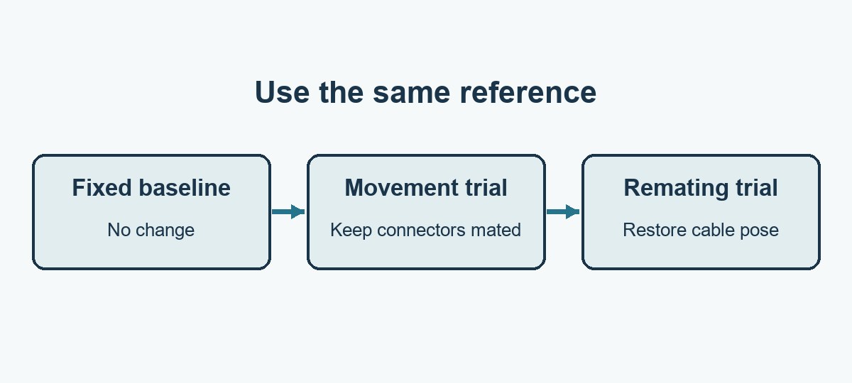
If a VNA curve changes when you move a cable, repeat the movement on a known reference before changing the PCB. Keep the connectors mated for that first experiment. Then put the cable back in its original position and run a separate remating check. If both changes happen together, the trace cannot tell you which one caused the difference.
A calibration corrects the setup as it was characterized. It does not make a bent cable, loose connector or moving antenna feed behave like the original setup. The question is whether the shift over your actual frequency band is small enough for the decision you are about to make.
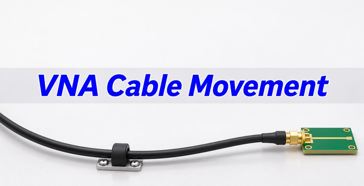
VNA Cable Testing: Change One Variable at a Time
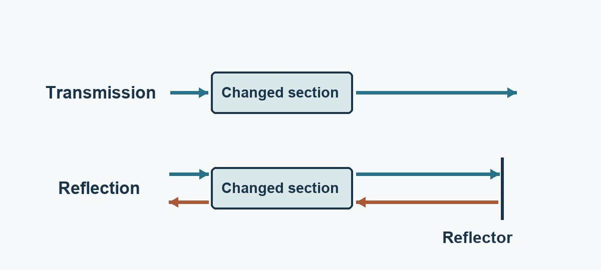
Start with a suitable verification standard at the intended reference plane. Take repeat sweeps with nothing moved, then sweep again after the approved range of cable motion without disconnecting anything. Return the cable to its starting pose and compare the trace again. For transmission use a suitable through reference; for reflection use a suitable characterized reflection reference as called for by your procedure.
Keep the device, adapter orientation, test settings and temperature stable. If a shift appears on the reference, do not attribute the equivalent shift on the product to its layout. If the reference returns to baseline only in one cable pose, clamp the cable there and reverify rather than assuming the post-calibration movement is harmless.
If the cables and reference are stable but a weak S21 trace appears to flatten, check whether receiver noise or fixture leakage limits the reading. The VNA IF bandwidth guide shows how to tell the two effects apart.
VNA Calibration: Keep the Reference Plane and Cable Pose Consistent
Identify which connectors define the calibration plane and which adapters remain outside it. Photograph the cable path, support the connector instead of loading it sideways, and use the specified mating procedure. If your verification standard is at the coax plane but the release claim is at the PCB trace plane, any intervening launch or fixture still needs its own error treatment.
Keep raw data before port extension, smoothing or gating. These options can support a valid procedure; they do not replace a stable path. For edge alignment during time-domain tests, see the differential TDR deskew guide. Its source and receive corrections solve a different problem from post-calibration VNA cable movement.
Phase Stable Cables: Compare the Flex Specification With Your Test
Choose a cable using the specified band, length, connector, bend radius and magnitude/phase stability under the documented flex condition. Phase-stable is not a universal error figure. A repeated sweep with a cable clamped in one place does not qualify a production fixture that needs to move through several positions.
| Option | Best fit | What to verify |
| Test cable held in a fixed route | Repeated boards with consistent connector location. | Stationary baseline and repeatability after normal mating. |
| Qualified phase-stable flexible cable | The test requires a defined range of movement. | Magnitude and phase at the positions and over the band used in the test. |
| Board-specific pigtail or adapter | Physical access requires a nonstandard connection. | Repeatability of the complete path; do not transfer a bench cable rating to the pigtail. |
Follow the cable manufacturer’s bend and handling limits. Do not force a tighter bend just to make a trial more sensitive, or assume an adapter has the same mechanical limits as the main test cable.
S21 Phase: Turn a Delay Shift Into Degrees
For a pure added delay Δt in one transmission path, the magnitude of phase change at frequency f is 360° × fΔt, before phase wrapping. At 10 GHz, 2 ps corresponds to 7.2°. For an ideal reflection that traverses that same changed section on both the outgoing and return path, the corresponding phase change would be 14.4°. That factor of two is not a rule for every S11 feature or a mismatched fixture.
Calculate phase differences consistently across the same frequency grid and handle wraparound. A linear phase change can be consistent with delay; ripple, an amplitude shift or a changed notch shape means delay alone does not explain everything. Inspect raw magnitude as well as phase before applying a correction.
S11 Measurement: Separate Cable Error From Antenna Interaction
For a matched load, reflection phase can be too noisy to serve as the sole stability check because very little signal returns. Check complex reflection or its magnitude as appropriate, and choose a characterized reference suitable for the phase question. Do not judge a phase jump at a deep reflection null in isolation.
For a small antenna, cable routing can also change the system being measured by interacting with its ground or field. If a reference is stable but the antenna response still moves, repeat with the use-representative feed geometry, body or enclosure. Verify the actual acceptance metric, such as the agreed S11 limit and frequency range, in that defined configuration.
VNA Measurement Uncertainty: Budget the Motion Separately
Set a setup repeatability budget tighter than the differences you need to distinguish, and separate stationary variation, motion and connector remating. The example below is a hypothetical 6–10 GHz PCB coupon test. The project allocates at most 0.10 dB and 5° to the observed change during permitted setup motion. These are example limits, not instrument specifications.
| Change from fixed reference | Worst magnitude / phase change in band | Example action |
| Nothing moved | 0.02 dB / 1.0° | Record the stationary comparison. |
| Cable moved, connectors not opened | 0.13 dB / 7.2° | Exceeds both allocations; stabilize or change cable setup before use. |
| Fixed route, reference remated | 0.04 dB / 4.8° | Inside the example limits, but phase has only 0.2° of margin; repeat under the approved rule. |
Enter separate rows for each condition, and report the frequency of each worst change. The worst magnitude and phase changes need not occur at the same point. These observed changes are repeatability evidence, not a complete uncertainty statement or values that may always be added or root-sum-squared.
VNA System Verification: Confirm the Reference After a Change
After changing the cable route, replacing an adapter or tightening a loose clamp, verify the reference again under the intended conditions. Recalibrate when the approved procedure requires it. Use the same sweep settings, plane and reference type, then repeat the motion or connection sequence that the test actually needs.
For a transmission coupon, compare phase and insertion-loss change across the full band. For an antenna, confirm the reference and then repeat the device with the controlled feed geometry. For a near-limit production result, do not release on a narrower graph scale or a new cable pose chosen after the test. Use the agreed repeatability, uncertainty and disposition rules.
VNA Test Data: Record Which Setup Produced the Result
Record cable and adapter IDs, reference plane, frequency band, sweep settings, mechanical route, reference standard, test timestamp and the raw results for fixed, moved and remated conditions. Keep the before and after traces on a common axis. One sample entry might be: “Fixture A, 6–10 GHz; fixed 0.02 dB/1.0°; flex 0.13 dB/7.2°; hold until cable restraint is verified.”
When the reference repeatability is comparable to the difference between two PCB revisions, report the comparison as inconclusive. If repeatability is validated and the result follows the board on the same setup, investigate the board construction or launch with the same controlled evidence.
VNA Cable Movement FAQs
Can flexing change the S21 phase without much loss change?
Yes. Changes in electrical delay can shift phase without a comparable change in magnitude. Measure both quantities and compare them with separate limits.
Do I need to recalibrate after every small movement?
Follow the approved procedure and validated motion envelope. If the known reference no longer reproduces, correct the setup and recalibrate or reverify as required.
Will a shorter test cable always be more stable?
No. Construction, connector support, bend radius and how the cable is moved matter. A shorter cable forced into a tight bend can be a poor choice.
Can port extension remove cable motion?
It can account for an appropriate fixed delay. It cannot restore repeatability when the cable changes shape or remove an unstable connector mismatch.
How do I separate cable movement from a loose connector?
First move the cable within the approved range without disturbing the connector. Then deliberately remate in the same supported pose under the specified procedure, and compare both results.
Why can a reference look stable while a small antenna still changes?
The cable can interact with the antenna or its ground in ways that do not occur with a coaxial reference. Verify antenna geometry separately.
Is 5° an acceptable phase change for any PCB test?
No. It is an example budget. Use the actual frequency band, test uncertainty and decision margin to set the allowed change.
Should I compare only one frequency?
Only when the acceptance requirement is at that frequency. Otherwise compare across the complete required band and record where the worst change occurs.
Technical References
- Keysight: VNA System Verification; verification configurations and cable flex contribution.
- Rohde & Schwarz: ZV-Z9x and ZV-Z19x test port cables; cable handling and flex effects.
- Rohde & Schwarz: VNA Calibration Methods and Standards; what measurement calibration corrects.
- Controlling the Effects of Feed Cable in Small Antenna Measurements; original experimental work on feed-cable interaction.
Custom RF PCBs With Stackup and Test Coupon Review
Send EBest Circuit your stackup, RF test geometry, connector-launch drawings, target band, and the quantities you need. A pre-fabrication review can help define which structures to include on a coupon and where to place the measurement reference plane in your test plan. Request a quotation at sales@bestpcbs.com.
You may also like
Tags: phase stable cables, S Parameters, vna cable movement, vna calibration