Ceramic laser drilling makes holes in substrates such as fired alumina. The issue isn’t just whether the laser can open a hole. The entrance and exit can be different sizes, and the smallest opening may be inside the bore. Start by specifying what the hole does and which dimension controls that function.
Take an alumina sensor board with a locating pin and a separate electrical through-connection. The locating hole has to fit and align; the via has to conduct after metallization. Both may look fine from above and still fail for different reasons. Here is how to specify them, compare tolerances and read a report you can actually use.
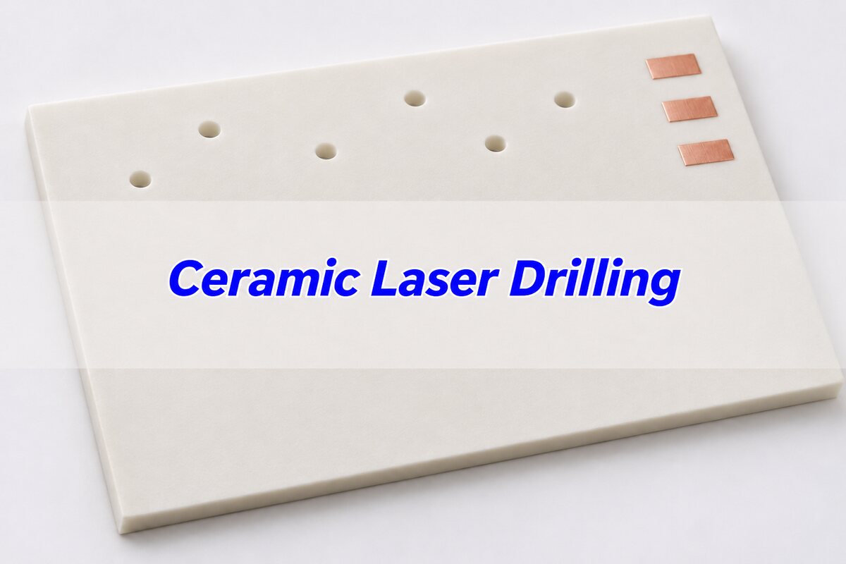
What Is Laser Drilling? Start With the Hole’s Job
A laser removes material locally until the opening reaches the far side. The hole can serve as a mechanical passage, carry a conductive connection after metallization or give access to a feature. A through-hole is not a scribe: a scribe deliberately leaves a web that later breaks. For panel separation, use the separate ceramic laser scribing guide.
Decide what is allowed to touch the bore. If the pin passes through, control the smallest usable opening through the thickness. If it only seats at one face, shoulder contact and face geometry may matter more. If the bore is meant to conduct, make the distinction between the drilled ceramic opening and the finished metal-lined feature explicit.
Laser Drilling Process: Why the Two Faces Can Differ
Material removal depends on how the beam interacts with the ceramic along the depth. The bore can taper, and the two rims can have different roundness or debris. An entrance measurement alone doesn’t tell you the exit size or wall condition. Use the material, thickness and processing sequence actually proposed; a process qualified for one alumina grade is not automatic approval for a different construction.
Ask the fabricator what is inspected after drilling, after cleaning and after any metallization. Those stages answer different questions. A published alumina drilling study evaluated entrance and exit circularity, taper and the heat-affected zone separately. Those are useful inspection categories, not a recipe or a release limit for your drawing.
Drilled Hole Diameter Tolerance: Specify the Measuring Face
Do not put “Ø0.26 mm” on the drawing without saying where and when it applies. Some suppliers define hole diameter at the laser exit. For example, LCP’s published guideline lists a standard exit-side diameter tolerance of ±0.050 mm; Accumet publishes ±0.001 in (±0.0254 mm) for its exit diameter. These are different suppliers’ guide values, not EBest Circuit’s capabilities or substitutes for a quote on your part.
| Drawing field | What to specify | Why it matters |
| Exit diameter | Minimum or nominal plus tolerance at the named face. | Prevents an entrance-only pass. |
| Through-bore requirement | Minimum clear opening or agreed functional gauge. | A restriction inside can stop a pin even if both faces look acceptable. |
| Inspection stage | As drilled, after cleaning or after metallization. | Stops unlike measurements from being compared. |
| Roundness if critical | How diameter is fitted or how clear passage is tested. | A single reported diameter may not bound a non-round opening. |
Use the supplier’s actual convention for identifying the faces. If the board is flipped during processing, the laser entrance is not necessarily the side called “top” in assembly. Add a clear face ID alongside the hole note.
Hole Taper: Calculate the Diameter Difference
For a simple taper with a larger entrance, subtract the exit diameter from the entrance diameter. If a report expresses taper as a percentage of substrate thickness, divide that difference by thickness and multiply by 100. Don’t compare this percentage directly with degrees or a one-side wall angle.
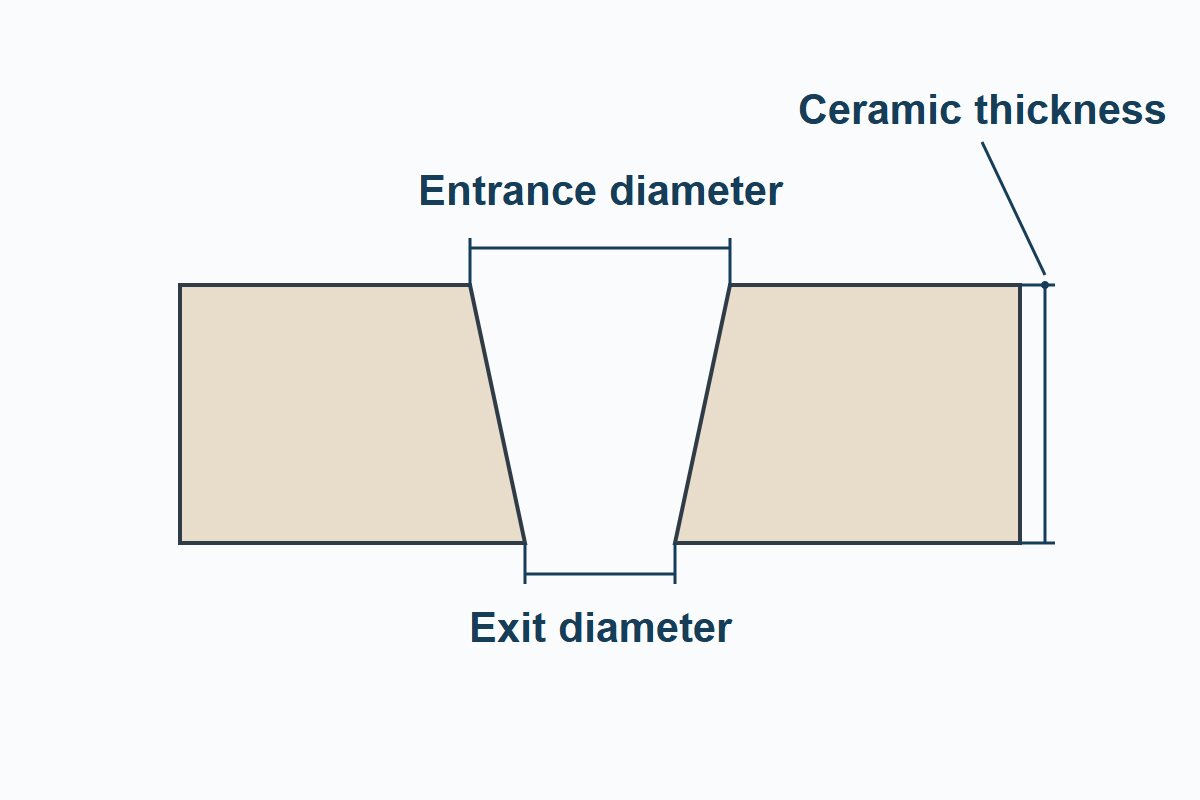
In the example, the substrate is 0.630 mm thick. The entrance is 0.300 mm and the exit is 0.260 mm. The diameter difference is 0.040 mm, or 6.35% of thickness. This is a teaching calculation, not a measured sample or a recommended tolerance.
LCP’s guide, Rev. 07, p. 9 gives a taper limit of 7% of thickness using the entrance-to-exit diameter difference. Accumet’s Figure 3 guideline gives 10% of thickness with a 0.005 in maximum. Before comparing quotes, confirm whether both suppliers are quoting the same grade, thickness, measurement definition and stage. Don’t combine one supplier’s tightest diameter value with the other’s taper rule.
Hole Position Tolerance: Measure From the Assembly Datum
Diameter does not tell you where the hole landed. A locating hole may be the correct size and still miss its pin if the hole pattern shifted relative to the mating fixture. Reference its position to the features the assembly actually uses, not a convenient panel edge that is removed later.
For the sensor board, identify the frame or features that locate the tile, the face from which position is evaluated, and whether the measurement refers to final singulated parts. For an electrical via, also check registration to the conductor on the relevant side. Ask for the measured positions against the drawing revision, rather than a bare statement that the laser stage met its own accuracy figure.
Plated Through Hole vs Non Plated Through Hole in Ceramic
| What the hole does | What to control | Evidence that matters |
| Mechanical locating hole | Usable bore, position, rim condition. | Agreed measurements or fit check on the finished tile. |
| Electrical through-connection | Finished geometry, wall metallization and land registration. | Agreed section evidence and electrical continuity or resistance, where required. |
An open ceramic bore is not an electrical connection. Ask how the wall is metallized or filled and whether the chosen sequence changes the remaining opening. A fit gauge won’t show breaks in the conductive path. Conversely, electrical continuity doesn’t prove a mounting pin will fit. Keep one acceptance criterion for each function.
Heat Affected Zone: Check the Rim and Wall Separately
Look for chips, visible cracking, debris or resolidified material at the entrance and exit. An optical image of the rim can help flag a problem, but it cannot prove the wall is free of hidden cracking or that a metallized via is continuous. If the risk is inside the bore, specify an inspection method that reaches the wall, such as a representative cross-section agreed with the fabricator.
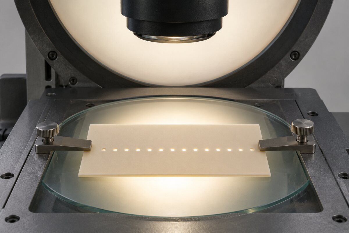
Separate what was seen from what the cause might be. A damaged rim warrants inspection and review, not an automatic conclusion about the beam or the process. Check the defined cleaning, handling and inspection stages before assigning a root cause.
Hole Diameter Measurement: Read the Report Before Release
Look for the drawing revision, sample ID, material and thickness, face IDs, measurement method, condition of the bore and the applicable limits. A report that lists one diameter but doesn’t say which face was measured is incomplete when the exit controls the fit.
| Hypothetical requirement | Example result | Decision |
| Exit ≥0.250 mm | 0.260 mm | Meets shown exit criterion. |
| Diameter difference ≤0.050 mm | 0.040 mm | Meets shown taper criterion. |
| Full passage and locating position | Not reported | Do not release solely on face diameters. |
To use the table, start with the requirement on the approved drawing, pair it with a measurement taken on the same feature and at the right stage, and apply the agreed decision rule. If readings sit close to a limit, check measurement uncertainty and repeatability with the supplier. The numeric limits above belong only to this example. No single IPC hole rule is asserted for a fired ceramic bore; apply the requirements called out for your product and process.
Ceramic Laser Drilling FAQs
Should I put the hole diameter on the laser entrance or exit?
Specify the face that controls your function. If both matter, give separate conditions. If a pin goes all the way through, also specify the usable bore requirement.
Is the exit always the smallest point?
No. It can be the controlling face in a tapered profile, but a restriction inside the wall can be smaller. Verify the bore when fit depends on it.
What is the difference between taper percent and taper angle?
Taper percent here is the diameter difference divided by thickness. An angle refers to wall geometry and must identify whether it is measured per side or included.
Can I use the alumina hole tolerance for aluminum nitride?
Don’t transfer it automatically. Confirm the grade, substrate thickness, process and measured stage for the requested material.
Does a laser-drilled hole arrive electrically conductive?
Not by drilling alone. A conducting through-connection needs the specified metallization or fill and contact to the required lands.
Will cleaning remove every laser-related defect?
No. Cleaning can remove some residue, but it doesn’t prove geometry, wall integrity or the absence of cracks.
Can I use one optical photo to approve both faces?
Only if the agreed method actually distinguishes what it claims to measure. Otherwise request separately identified views or measurements.
What should I send for a ceramic PCB quotation?
Send the artwork, outline and drill drawing with face IDs, material, thickness and quantity. Identify which holes are mechanical and which need an electrical connection.
Technical References
- LCP: design guideline for alumina and AlN, Rev. 07
- Accumet: ceramic laser processing design guideline, Figure 3
- Bharatish et al.: measuring circularity and heat effects in laser-drilled alumina
Custom Ceramic PCBs with Engineering DFM Review
Request a quote from EBest Circuit for your custom ceramic PCB. Our engineering DFM review checks the proposed ceramic construction and helps identify which drawing details need confirmation before production. We can review material and metallization options against your requirements.
Email sales@bestpcbs.com with your drawings, circuit artwork, proposed material and quantities. Flag any functional holes, dimensions, inspection requirements or assembly interfaces that the quote needs to cover.
You may also like



Tags: Alumina Substrate, Ceramic Laser Drilling, Ceramic PCB DFM, Hole Taper