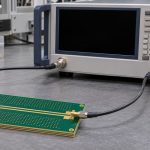
PDN antiresonance is an impedance peak caused by interacting paths in a power delivery network. Adding a capacitor can lower impedance at one frequency and raise it at another. Compare the complete impedance curve with the rail’s target band before deciding that a new part has improved decoupling.
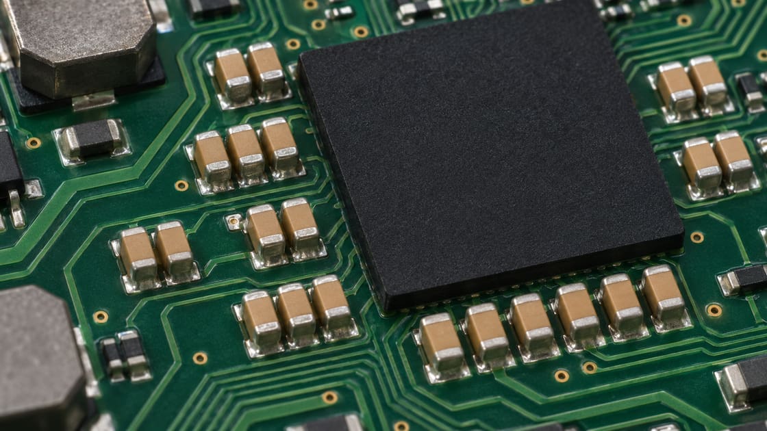
Why two capacitors can make a peak
Between the self-resonant frequencies of two capacitor branches, one branch can behave mainly inductively while the other behaves mainly capacitively. Their admittances can partly cancel, leaving less total admittance and therefore higher impedance. Losses in the branches and the rest of the network limit the height of the peak.
What parameters should go into the model?
Use a mounted model at the expected operating conditions. A nominal capacitance list is useful for BOM control but cannot predict the locations of peaks by itself.
| Input | Include | Why it matters |
| Effective capacitance | Part value under rail bias and relevant conditions | Shifts branch behavior |
| ESR | Frequency-dependent loss where available | Affects damping and peak height |
| ESL | Package plus mounting path when applicable | Moves resonance and changes high-frequency impedance |
| Common paths | Shared via, plane and regulator connections | Can dominate after adding more capacitors |
| Observation port | Load location and reference | Changes what the result represents |
Self-resonance vs antiresonance
A capacitor branch’s self-resonance often appears as an impedance minimum. An antiresonance of the combined network appears as an impedance maximum. Treat them as different diagnostic clues. Analog Devices’ decoupling guide explains the ESR and ESL effects on the individual capacitor curve.
Compare three ways to address a peak
Start by asking whether the aim is to remove a troublesome interaction, add damping, or reduce the inductance that limits the bypass path.
| Change | When to consider it | What to verify |
| Repeat an effective capacitor value | The existing value has a useful mounted response and enough sites are available | Shared inductance and remaining peaks |
| Change the value mix | A separate band still needs support | New peaks between branches and at system interfaces |
| Add controlled damping | A narrow peak remains above target | Loss, rail transients, and regulator stability |
| Improve mounting | Capacitors are isolated by long connections or shared vias | Impedance at the actual load port |
Set the target before touching the BOM
Use the rail’s allowed voltage deviation and relevant load change to form a first-pass impedance target. The ratio is an engineering starting point, not a guarantee across all frequencies or time scales. Define the relevant frequency band and keep regulator behavior and package effects in view.
A worked example: a lower dip does not mean a better rail
Imagine a preliminary target of 50 mΩ in a defined band. A new capacitor reduces an existing minimum from 25 to 15 mΩ but creates a 75 mΩ peak within that band. The change fails that illustrative check even though the minimum improved. Compare the worst relevant excursion, not the deepest dip.
Why mounting can matter more than the printed value
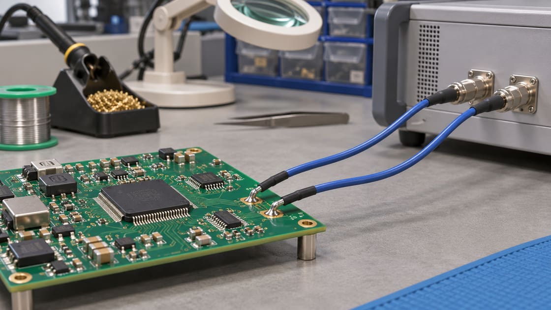
Current reaches the capacitor through the pads, vias, and return path. Inductance in that loop changes its mounted response. Moving the part or providing a shorter return can help a different band than changing the nominal capacitance. Use a model or test that represents the actual placement.
What a ferrite bead changes
A bead adds frequency-dependent impedance and can form another resonant network with nearby capacitors. Its response also changes with operating conditions. Analog Devices AN-1368 discusses peaking and damping for bead filters. Do not assume a bead automatically improves a rail that already has a narrow peak.
Compare curves at the same observation point
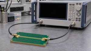
Measure or model at the same location, with the same reference and configuration, before comparing a change. A curve at the regulator output may look different from one at a device load. An uncontrolled change of port, cables, or fixture can mask the effect of the capacitor.
Confirm an apparent peak before revising the design
Check the fixture and noise floor, then compare the response after a deliberate small change such as removing one suspect branch. A predictable movement of the peak is more informative than a single sweep. Preserve the original and revised traces, model, and operating conditions together.
Check the rail in time as well as frequency
A frequency sweep exposes impedance over a range, while a load transient shows how the rail responds to a particular event. The two are complementary. Verify the response under representative loading and keep the regulator’s permitted capacitance and ESR range in the review.
What to share for a PCB design review
Send the stackup, capacitor placements, rail and return layers, and measurement reference to Best Technology at sales@bestpcbs.com. If the rail budget is not yet defined, start with the BestPCBs PDN target impedance guide, then use this article to check whether any peaks exceed it.
FAQ
Is using several capacitor values always a bad idea?
No. A deliberate value mix can help cover different frequency bands. The risk is assuming that individual impedance minima automatically combine into a smooth curve. Compare the mounted network with the target and verify how the regulator, plane paths, and device interact with the selected capacitors.
Can identical capacitors remove every antiresonance?
No. Repeating the same value may reduce a particular interaction, but other peaks can involve the bulk capacitors, regulator connection, plane inductance, or package. Common mounting inductance can also limit the benefit. Check the complete curve at the load rather than inferring the result from the BOM.
Is a higher peak always a problem?
Its impact depends on whether it falls inside the relevant current spectrum and exceeds the applicable target at the observation point. Also consider the shape and width of the peak. A design decision should include the actual rail budget and a representative load transient check.
Why does the measured peak move when I power the board?
The effective capacitance of some ceramic parts can change with applied voltage, and the regulator and load can change the network response. Verify that the measurement setup is appropriate for the energized rail. Document the bias and operating state before comparing powered and unpowered sweeps.
Does adding ESR always fix the problem?
Loss can reduce a high-Q peak, but the location and amount of damping matter. Added resistance can increase impedance elsewhere or affect regulator behavior. Compare the complete response and respect the regulator’s approved operating range, then verify that both the sweep and the load transient improve.
Can I predict the peak from the two datasheet self-resonances?
The self-resonances indicate where branch behavior changes, but they do not specify the peak of the mounted network by themselves. Layout inductance, capacitance under bias, branch losses, and other connections affect the result. Use mounted models and confirm the important features with a measurement.
Is a rail ripple reading enough to validate decoupling?
A ripple reading is useful for the specific operating condition and probe setup, but it does not reveal every impedance peak or load case. Use a suitable frequency-domain check alongside representative time-domain testing. Keep the measurement point and conditions consistent when comparing revisions.
Should I always replace a mixed network with a single value?
No. Treat a single-value layout as one candidate. Compare it with the existing network and a damped alternative across the required band. Verify the total effective capacitance, regulator stability requirements, mounting constraints, and load response before changing the production bill of materials.
You may also like


Tags: Antiresonance, PCB Decoupling, PDN, Power Integrity