On a PCB TDR reflection trace, the pulse travels to a discontinuity and back. For a uniform section, one-way distance equals propagation velocity times round-trip time divided by two. Check whether the instrument already displays one-way distance before applying the conversion, then map the result to the actual route rather than measuring across the board.
Why the reflection takes a round trip
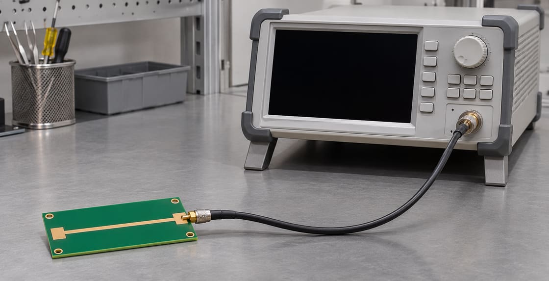
Time-domain reflectometry launches a fast change and observes the return at the measurement side. A mismatch can reflect part of that signal. The time difference from a defined reference to the reflection includes travel in both directions.
What to record with a marker
A distance is only as useful as its reference and velocity model.
| Field | Unit or definition | Example only |
| Time interval | ns, measured as round trip | 0.80 |
| Propagation velocity | mm/ns | 160 |
| Reference plane | Physical boundary | Coupon input launch |
| Computed one-way distance | mm | 64 |
| Instrument axis | Time or configured distance | Confirm before converting |
Convert the sample reflection time
Multiply 0.80 ns by 160 mm/ns and divide by two to get 64 mm. Without the divisor you would look near 128 mm. Keysight’s TDR concepts describe round-trip reflection timing and calibration with a known line.
TDR time vs displayed distance vs TDT
First identify what the instrument marker actually reports.
| Reading | Meaning | Conversion |
| Raw reflection interval | Outbound and return time | Multiply by velocity and divide by two |
| Configured TDR distance | Instrument-scaled distance | Verify settings; do not halve again |
| Through transmission delay | One-way delay for a defined transmission measurement | Do not use the reflection divisor |
Calibrate velocity on a known route
Use a known physical length with the same relevant transmission geometry when practical. If a 40 mm reference span corresponds to 0.50 ns round trip, its inferred velocity is 160 mm/ns. Use the same reference convention when applying that value to the unknown feature.
Set the reference before interpreting the event
Decide whether your origin is the instrument port, the connector plane or the PCB trace start. The cable and launch contribute delay if they remain in the measurement. Record the calibration or fixture treatment rather than quietly assuming time zero is at the board.
Map distance along the route
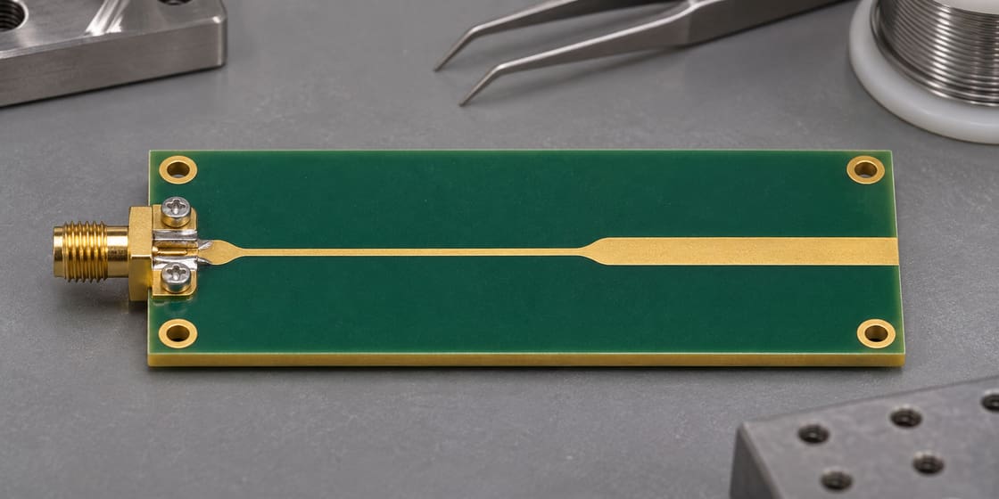
Use cumulative distance along the traced conductor. A via or a bend can make straight-line separation misleading. Note which layer and routing segment the candidate feature occupies and check the positions of known launch or termination events.
Use separate delays for mixed structures
A cable, microstrip and stripline need not share one velocity. Account for their segment delays or use a suitable calibrated reference. Applying a single factor to an entire mixed route may move the apparent feature even when the reflection time is correct.
Know how close two events can be
Finite effective rise time and bandwidth can make neighboring reflections overlap. An apparent peak may represent more than one feature. Do not infer a precise physical location from a cursor whose resolution exceeds the information in the measurement.
Check alternatives before naming the fault
An impedance change, connector transition, stub or termination can all create a reflection. Compare a good unit or controlled fixture and use the layout to narrow possibilities. The marker alone does not tell you whether the feature is an open, a defect or a normal transition.
Keep impedance and location separate
The reflection magnitude and inferred impedance describe the event under the test conditions. Its delay estimates where to look. Compare with the BestPCBs signal transmission guide for other channel verification tasks.
Save the setup with the result
Preserve raw data, axis settings, velocity basis, reference plane, route coordinates and candidate features. For a stackup or test coupon manufacturing review, share the files with Best Technology at sales@bestpcbs.com.
FAQ
Why is my calculated distance twice the expected value?
The marker may be showing round-trip time, and the calculation may have omitted the divisor of two. Confirm the axis and reference before changing the velocity setting. If the display is already calibrated in one-way distance, do not apply the divisor again.
Can I use the speed of light for a PCB trace?
Not as the actual line velocity unless the propagation medium and geometry support it. A PCB transmission line normally propagates more slowly. Use a measured or modeled velocity appropriate to the actual route, and label any screening assumption in the test record.
Can I use the same velocity factor on every layer?
Not without checking the construction. Different layers can have different dielectric materials, field distributions and reference structures. If the route crosses layers, evaluate each relevant segment or compare with a calibrated structure that represents the full path under the same conditions.
Is the distance the same as straight-line distance on the board?
No. It corresponds to travel along the electrical path. A serpentine can place a feature far along the route while it is physically close to the connector in a top view. Map against cumulative trace distance, including relevant transitions, instead of a ruler across the board.
Can a known cable remove all fixture effects?
A known cable can help establish timing, but launches and adapters can still contribute reflections or delay. Set the correct calibration reference and inspect a suitable reference fixture. Do not assume velocity calibration is equivalent to removing fixture mismatch or loss.
Why does a strong reflection not prove a broken trace?
A normal connector, impedance step or termination can also produce a strong return. Compare with the expected layout and a known good reference. Use additional evidence before assigning the reflection to a crack, open or manufacturing defect at the estimated location.
What if the instrument shows distance in free space?
Confirm whether the plotted axis already applies the medium velocity factor. A free-space-scaled distance is not the physical PCB distance. Follow the instrument documentation and verify with a known length before accepting a marker position as a measured route location.
Can I use the same formula for transmission delay?
Only after identifying the timing convention. Transmission from one end to the other is ordinarily a one-way measurement, so its distance relation lacks the reflection divisor. Keep the acquisition mode and reference planes in the report so the calculation is not misapplied.
You may also like


Tags: PCB Fault Location, Propagation Velocity, Signal Integrity, TDR