The common mode choke vs differential mode choke comparison comes down to which current the component is intended to impede. A common mode choke mainly suppresses noise flowing in the same direction along paired conductors, while a differential mode choke suppresses unwanted current variations in the outgoing-and-return circuit. Their magnetic behavior explains why two chokes with similar inductance labels may perform very differently.
EBest Circuit (Best Technology) provides PCB fabrication, component sourcing and PCB assembly for customer designs. For boards containing EMI filters, combining these services keeps the specified components and PCB build within one manufacturing workflow. Contact sales@bestpcbs.com to discuss fabrication and assembly for your approved circuit.
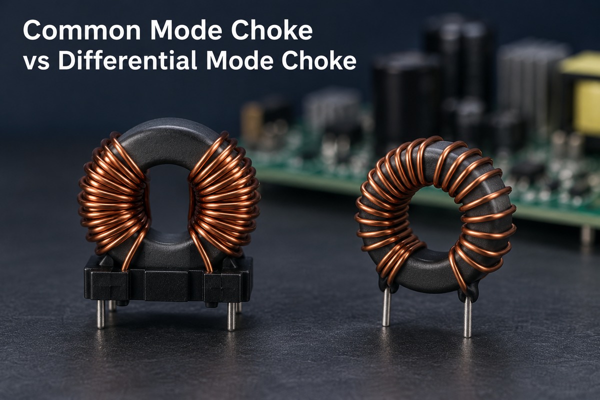
What Is the Difference Between a Common Mode Choke and a Differential Mode Choke?
The main difference is how each choke responds to the current path. Common mode noise travels along both conductors relative to another return path, such as chassis or parasitic capacitance. Differential mode noise circulates between the conductors.
| Characteristic | Common mode choke | Differential mode choke |
|---|---|---|
| Main filtering purpose | Suppress common mode noise | Suppress differential mode noise or ripple |
| Typical construction | Coupled windings sharing a core | A series inductor, or a suitable coupled arrangement |
| Normal load-current flux | Largely cancels in a balanced pair | Must be accommodated by the magnetic design |
| Useful impedance | High common mode impedance in the target band | High differential mode impedance in the target band |
| Important limitation | Leakage and parasitics affect differential transmission | Load current can reduce inductance through saturation |
The distinction is not simply “high frequency versus low frequency.” Either noise mode can occur across a range of frequencies. The current path identifies the mode; the component’s impedance curve shows where it can provide useful suppression.
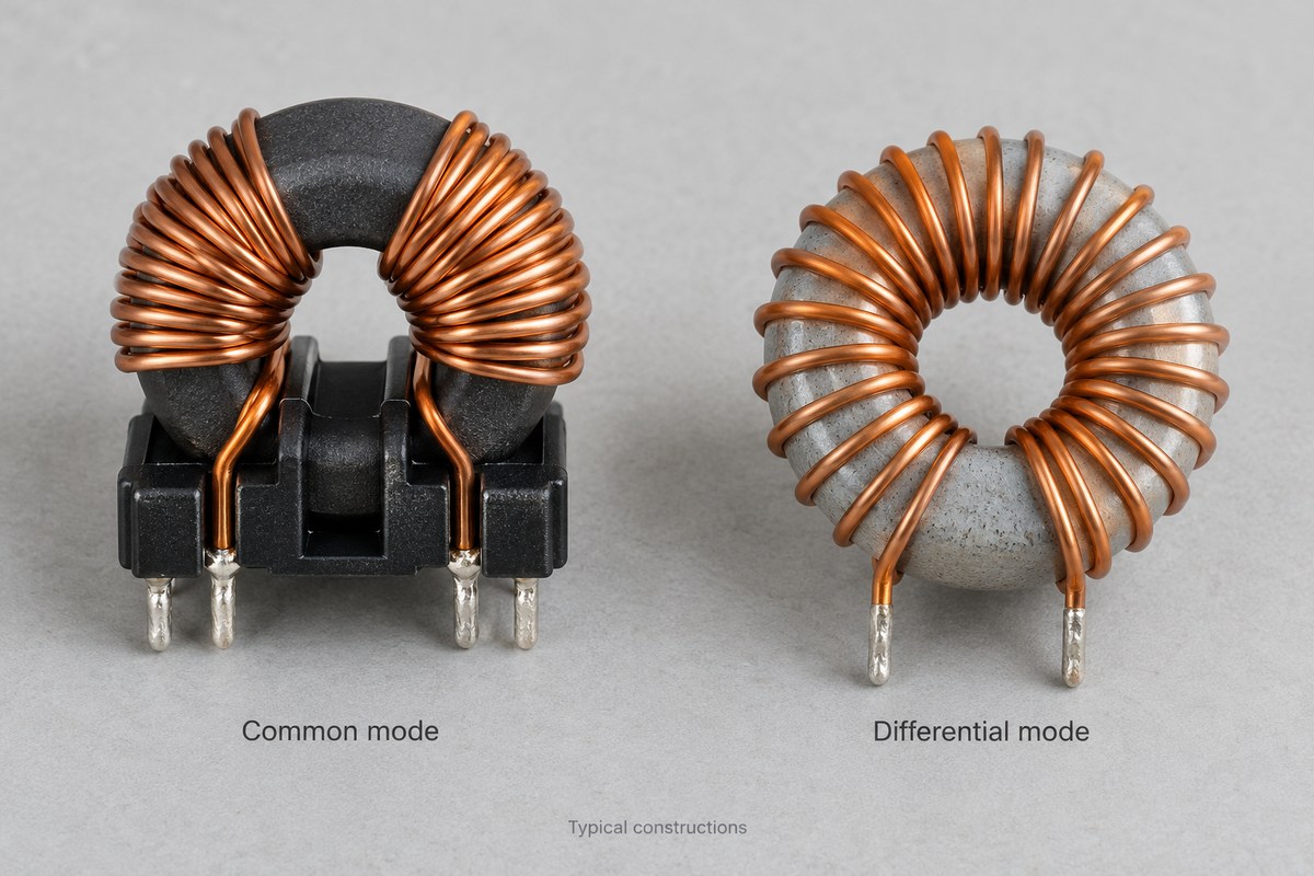
How Does a Common Mode Choke Work?
A common mode choke uses magnetic coupling to respond differently to two current patterns. In a typical two-line device, each conductor passes through a separate winding on the same core.
- During normal power delivery, current goes to the load through one winding and returns through the other. With the intended winding connections, equal and opposite currents produce opposing core flux. The cancellation allows load current to pass with little impedance from the coupled inductance.
- For common mode noise, current flows in the same direction along both conductors. The resulting core flux adds, producing an impedance that opposes this noise current.
“Same direction” uses the same reference direction for both wires. The noise still needs a return path, which may include chassis connections or stray capacitance outside the pair.
Flux cancellation does not make the component lossless. Winding resistance still causes heating, and imperfect coupling creates leakage inductance. These effects explain why a real choke does not pass every differential signal unchanged.
How Does a Differential Mode Choke Work?
A differential mode choke adds inductive impedance to the circuit carrying the outgoing and return current. A simple implementation places an inductor in series with a power conductor. Some filters use inductors in both conductors or a coupled design.
The inductor opposes changes in current. Together with the surrounding circuit and filter capacitors, it can reduce unwanted ripple or conducted noise while passing the required DC or lower-frequency power.
Unlike balanced current in a common mode choke, the load current in a simple differential inductor produces core magnetization. The component therefore needs enough inductance at the actual operating current, not only under a small-signal test.
If the core approaches saturation, inductance falls and filtering can weaken. Gapped cores and distributed-gap materials are common ways to accommodate the stored magnetic energy. The appropriate construction depends on the current, frequency and loss requirements; there is no single core material for every differential mode choke.
Can a Common Mode Choke Replace a Differential Mode Choke?
Sometimes, but only when its differential mode performance is sufficient for the circuit. A common mode choke’s leakage inductance can contribute useful differential filtering. Some dual-mode components are deliberately designed to provide both functions.
| Situation | What it means for replacement |
|---|---|
| Only common mode inductance is specified | There is insufficient information to assume equivalent differential filtering |
| Leakage inductance or differential impedance is characterized | Its contribution can be evaluated in the actual filter |
| A dual-mode component meets both filtering requirements | A separate differential choke may be unnecessary |
| Differential attenuation remains insufficient | Additional differential filtering is still needed |
A “10 mH” common mode rating does not mean the circuit receives 10 mH of differential inductance. Measurement connections and the manufacturer’s definitions matter.
There is also an application distinction. In a power filter, differential attenuation may remove unwanted noise. In a data interface, excessive differential attenuation can damage the wanted signal. More differential impedance is not automatically an improvement.
When Are Both Types of Choke Used in an EMI Filter?
Both can be used when common mode and differential mode noise each need additional attenuation. A switching power supply may generate both, so reducing one mode can leave the other as the dominant problem.
In an AC input filter, the elements can serve different roles.
- The common mode choke contributes series impedance to common mode noise on line and neutral.
- Differential inductance and an X capacitor contribute to filtering noise between line and neutral. That inductance may come from a separate choke or a characterized part of the common mode choke.
- Y capacitors, where the equipment design permits them, provide a controlled high-frequency return path for common mode noise. Their use depends on insulation and leakage-current requirements.
These functions do not prescribe one universal component order. The source, load, capacitors and parasitic paths influence the complete filter response.
An extra choke is unnecessary if the existing filter already provides sufficient attenuation under the required operating conditions. Conversely, adding inductance alone may introduce resonance rather than solve the remaining noise problem. Measurements of the assembled equipment establish whether the filter works as intended.
How Do Frequency and Current Affect Choke Performance?
A choke must provide useful impedance at the noise frequency while carrying the operating current within its limits. The inductance printed in a parts table describes only part of that behavior.
| Parameter | Effect on actual performance |
|---|---|
| Impedance versus frequency | Shows the band where the component opposes noise effectively |
| Self-resonance and parasitic capacitance | Can change the response and limit useful high-frequency filtering |
| Inductance versus current | Shows how bias affects the available differential inductance |
| DC resistance | Contributes voltage drop and winding heating |
| Rated current and temperature conditions | Define the thermal limits under the manufacturer’s stated conditions |
| Differential insertion loss | Indicates how much a data-line choke affects the wanted differential signal |
Thermal current rating and saturation current are different limits. A winding can become too hot even when magnetic flux cancellation works well. A differential inductor can lose inductance before its temperature becomes the most obvious issue.
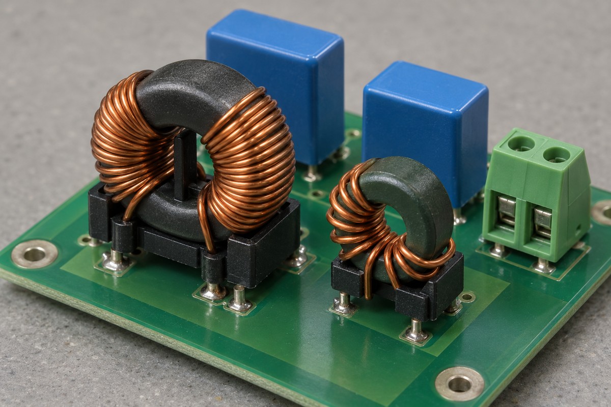
PCB implementation also affects the result. Coupling between the noisy and filtered sides can allow noise to bypass the intended filter path. Component placement, return paths and connection lengths therefore belong in the evaluation of the assembled board, alongside the choke’s data.
For a signal interface, the relevant question includes whether the wanted waveform remains acceptable. For a power input, it includes filtering across the load range and expected temperature. The same package size or nominal inductance does not establish equivalence between these applications.
FAQs About Common Mode Choke vs Differential Mode Choke
Can I identify the choke type by its appearance?
Not reliably. Two windings on one core suggest a coupled device, but the pin connections and intended operating mode determine its function. The schematic and datasheet are more useful than shape or color.
Does a common mode choke block a differential data signal?
A suitable data-line choke is designed to pass the required differential signal while attenuating common mode noise. Its differential insertion loss and bandwidth still matter; a power-line choke is not automatically suitable for a data interface.
Can common mode chokes be used on DC power lines?
Yes. The outgoing and return conductors can pass through the paired windings so their normal DC flux largely cancels. The device still needs appropriate current, temperature and insulation ratings.
Are equal inductance values enough to compare the two types?
No. Common mode inductance, differential inductance and leakage inductance describe different measurement conditions and responses. Compare the relevant impedance and current-dependent behavior for the intended circuit.
Why can a choke run hot even when it suppresses noise?
Noise attenuation does not eliminate winding resistance or magnetic losses. Load current, high-frequency excitation, ambient temperature and cooling all affect temperature rise. Heating alone does not identify whether the remaining noise is common mode or differential mode.
Understanding common mode choke vs differential mode choke helps preserve the intended filter function when a circuit moves into production. For PCB fabrication, component sourcing and assembly of your approved design, contact EBest Circuit at sales@bestpcbs.com.