A PCB thermocouple records how hot a specific point on an assembly gets during reflow and how long it stays there. Place sensors where a joint may heat too slowly or a component may get too hot, then secure them so the readings reflect the assembly rather than the attachment. The profile must show that critical joints receive enough heat without exceeding the monitored component limits.

What Is a PCB Thermocouple and What Does It Measure During Reflow?
A PCB thermocouple is a welded junction of two dissimilar conductors fixed to a defined point on a populated circuit board. It records local temperature versus time at the junction; it does not measure the oven setpoint or provide one temperature for the whole assembly.
The contact point determines what the curve represents. A junction attached to a lead heel or pad can track solder-joint heating. A package-top junction checks component-body temperature. A sensor suspended above the board measures local air and cannot prove that a hidden termination reached the required soldering window.
Keep the conductors insulated up to the welded bead. If the bare wires touch before that bead, the contact can become a second measuring junction and shift the apparent location. Record the component reference, exact contact point, attachment method, channel number, and measurement purpose before the run.
Why Does PCB Thermocouple Placement Affect Temperature Measurement Accuracy?
A temperature trace is useful only when its sensing point represents the joint or component being checked. Joints connected to large copper areas may heat slowly, while exposed edge components may reach a higher peak. A well-attached sensor at a convenient but unrelated spot can still give the wrong basis for setting the oven recipe.
- Thermal mass: Large connectors, shields, transformers, and dense component groups usually heat more slowly than small exposed devices. Place the junction on the joint or body that could limit the process.
- Copper connection: A pad tied to a plane or heavy copper can lag behind a nearby isolated pad. Check the actual copper path instead of assuming adjacent joints behave alike.
- Airflow exposure: Board edges, leading corners, and unshielded parts may heat faster than central or shadowed areas. Add separate points when orientation or panel position changes airflow.
- Attachment mass: Excess solder or thick adhesive slows sensor response. The bead should touch the target directly with only enough material to hold it.
- Measurement target: Package temperature and joint temperature are different acceptance checks. Label every channel by both location and purpose.
Where Should Thermocouples Be Placed on a PCB for Reflow Profiling?
Place thermocouples at the points most likely to narrow the reflow process window. The minimum plan covers a suspected cold joint, a suspected hot point, and any component or termination with a critical temperature requirement. Add panel positions only when copper distribution, component loading, or airflow can make them thermally different.
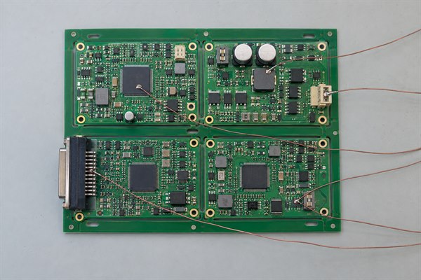
Choose candidate points from the assembly drawing, BOM, copper layout, panel orientation, and component limits. A cold-joint point matters when insufficient heat there could prevent an otherwise acceptable recipe; it need not be the lowest reading anywhere on the board.
| Profile Point | Recommended Location | Verification Target |
|---|---|---|
| Cold joint | Critical pad tied to a large plane, heavy copper, or high-mass component | Peak and time above liquidus at the slowest relevant joint |
| Hot point | Small exposed component or joint near a board edge | Maximum temperature and available upper margin |
| Critical joint | Exact lead heel, pad, or accessible hidden termination tied to reliability risk | Solder-joint thermal exposure at the required connection |
| Sensitive part | Specified package-body or lead location | Component temperature limit |
| Panel variation | Representative edge, center, leading, and trailing assemblies | Temperature spread caused by panel position |
Mark each location on an assembly drawing or photograph, including the exact contact point and why it is monitored. “TC4—U12 corner ball—cold-joint check” is more useful than “TC4” alone.
How Many Thermocouples Should Be Used for PCB Reflow Profiling?
Use enough channels to cover the thermal risks that could change the oven recipe. Roughly three to five points may cover a small, uniform assembly; a large panel or mixed-mass board may need six to twelve or more. The number depends on the actual risks, not a fixed profiling rule.
- Cover both extremes: Include at least one predicted cold location and one predicted hot or temperature-sensitive location.
- Add critical interfaces: Give separate channels to hidden terminations, high-reliability joints, or body limits that cannot be represented by the existing points.
- Sample real panel differences: Add edge, center, leading, or trailing positions only where layout and airflow make a different result plausible.
- Avoid measurement disturbance: Do not fill spare channels without a purpose. Dense wire bundles can alter airflow, pull on junctions, or interfere with the conveyor.
If the profiler lacks enough inputs, divide the plan into controlled repeat runs. Keep the oven recipe, conveyor direction, assembly state, and at least one reference channel unchanged so the groups can be compared.
Which Thermocouple Type and Wire Size Are Suitable for PCB Temperature Measurement?
Fine-wire Type K thermocouples are commonly suitable for electronics reflow profiling when they match the profiler input, connector polarity, temperature range, and insulation rating. A smaller conductor responds faster and disturbs a small joint less; a larger conductor is more durable but conducts more heat and needs more routing space.
About 0.2 mm wire is a practical choice for accessible joints; about 0.1 mm may help reach a BGA or fine-pitch target. These are examples, not required sizes. Choose a wire fine enough for the contact point but robust enough to stay attached through the planned runs.
- Profiler match: Confirm thermocouple type, connector type, polarity, and channel configuration before installation.
- Target access: Use finer wire when the junction must reach a hidden or closely spaced termination without bridging nearby conductors.
- Thermal response: Keep the welded bead and exposed conductor length small enough to follow the target rather than surrounding air.
- Mechanical life: Use insulation and strain relief that can survive the full oven cycle without softening, shorting, or contaminating the assembly.
How Should Thermocouples Be Attached and Routed on a PCB?
Fix the welded junction in direct, low-mass contact with the target and strain-relieve the wire before routing it toward the rear of conveyor travel. High-temperature solder is effective on accessible metal points; qualified high-temperature adhesive may suit package surfaces. Tape is better used for lead restraint than as the only precision contact at a solder joint.
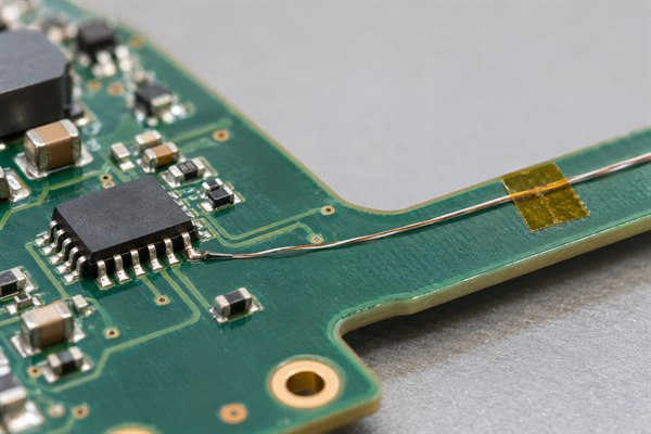
- Prepare the point: Clean and identify the exact pad, lead, joint, or package location. Confirm that the selected point matches the channel plan.
- Attach the bead: Use the smallest secure amount of high-temperature solder or approved adhesive. Under magnification, the junction should touch the target directly.
- Add strain relief: Restrain the lead a short distance from the bead. A gentle pull on the cable should not move the sensing point.
- Route the wire: Keep it close to the board, away from moving hardware and hot oven surfaces, and clear of the local airflow being measured.
- Check the channel: Verify continuity, polarity, channel label, and room-temperature response before the board enters the oven.
When high-temperature solder is used, the attachment alloy must remain solid during the measured cycle. Remove incompatible low-melting solder from a sacrificial profile point where necessary, and avoid a large solder fillet that would add thermal mass.
What Thermocouple Placement Challenges Occur with BGAs, QFNs, Large Components, PCB Panels?
Hidden joints, component bodies, and panel positions cannot all be judged from the same sensing point. When a joint cannot be instrumented directly, a nearby reading can help investigate heating, but it must not be reported as that joint’s temperature.
- BGA: A package-top sensor measures body temperature. It does not prove solder-ball temperature. Direct joint measurement may require a sacrificial assembly and controlled underside access to a selected ball.
- QFN or LGA: An exposed perimeter pad may not represent the center thermal pad. Use underside access or a purpose-built profile sample when center-joint behavior controls the decision.
- Large component: Connectors, transformers, and shields can create a slow joint while the component body has a separate maximum-temperature limit. Monitor both when either can restrict the recipe.
- PCB panel: Measure representative edge, center, leading, and trailing positions when panel layout or airflow can create a meaningful thermal gradient. Compare those positions before assuming that one assembly’s profile represents every board in the panel.
- Dense assembly: If simultaneous wiring would disturb airflow or prevent safe conveyor travel, use controlled repeat runs with a stable reference channel.
How Do You Evaluate Temperature Data from PCB Thermocouples During Reflow?
Compare each curve with the requirement for the point it actually measures. Joint traces use the selected solder-paste and alloy limits; component-body traces use the applicable component limit. Oven zone settings and conveyor speed are inputs, while the thermocouple curves show the temperature experienced by the assembly.
- Ramp rate: Calculate the heating slope where required and check whether fast and slow locations remain within the applicable process limits.
- Soak: Check the time and temperature range specified for the selected paste process, rather than applying a generic soak target.
- Time above liquidus: For each critical joint, measure the interval between the trace rising above and falling below the alloy’s liquidus temperature. Compare that interval with the selected paste’s process window.
- Peak temperature: Compare joint and package peaks with their own limits; one peak limit should not be applied to every channel.
- Cooling rate: Review the cooling slope when it is part of the product or paste requirement.
- Temperature spread: Compare decision-relevant channels in the same run. A cold joint and a hot package must both meet their respective limits; a small spread by itself does not prove either result.
Accept a recipe only when every critical joint and monitored package meets its own limit in the same run. If improving a cold joint pushes a component past its limit, change one controlled input—such as zone temperature, conveyor speed, or orientation—and profile again. Compare the new traces against the same channel locations and requirements.
What Causes Inaccurate PCB Thermocouple Temperature Measurements?
The most common causes are a moved junction, excessive attachment mass, damaged wiring, incorrect profiler setup, or a sensor placed on the wrong thermal object. Diagnose the trace together with the physical installation and channel record.
| Trace Pattern | Likely Cause | Corrective Check |
|---|---|---|
| Abrupt step or drift | Junction moved or lifted | Inspect the bead and strain relief; repair and repeat |
| Intermittent spikes | Loose connector, broken wire, or unintended conductor contact | Check continuity, insulation, polarity, and connector seating |
| Unusually slow response | Excess solder, thick adhesive, or heavy wire | Compare with a lower-mass attachment at the same target |
| Smooth curve but poor soldering result | Wrong target or surface proxy used as joint data | Match the channel record and photographs to the physical contact point |
| Poor run-to-run agreement | Attachment damage or changed loading, orientation, or board condition | Repeat under controlled conditions with one stable reference channel |
| All channels shifted | Wrong thermocouple type, logger setup, or cold-junction compensation | Verify the profiler configuration and perform a known-temperature check |
A smooth trace does not establish where the bead was attached. Reject a channel if its contact point cannot be confirmed after reflow, and repeat the measurement with a documented attachment.
How Can You Verify That PCB Thermocouple Measurements Are Reliable?
Check the sensor before and after reflow, confirm the profiler settings, and repeat the critical measurements. Compare runs only when the board revision, channel map, and oven recipe match.
- Inspect the installation: Verify bead contact, attachment size, insulation, strain relief, polarity, and connector seating. Save close-up photographs of every point.
- Test channel identity: At a stable room temperature, apply a controlled touch or heat stimulus to each junction. Only the expected channel should respond.
- Confirm the profiler: Check thermocouple type, sample interval, trigger, channel labels, and calibration status. Save the configuration with the run.
- Profile the real thermal load: Use the intended panel, component population, carrier, conveyor direction, and loading condition. Record any deviation.
- Inspect after reflow: Reject data from a junction that moved, lifted, shorted, or was damaged. Match accepted traces to the saved photographs.
- Repeat the run: Hold the recipe and assembly conditions constant, then compare peak, time above liquidus, ramp, and spread on the critical channels.
Reprofile when a change can alter heat transfer or the allowable window. Typical triggers include a new paste, a package or component-mass change, revised copper or stackup, a new panel layout, a different carrier, major oven maintenance, or transfer to another production line.
FAQs About PCB Thermocouple Placement and Reflow Profiling
Q1: Can a bare PCB be used for reflow profiling?
A1: A bare board cannot establish the final assembly profile. Components, solder deposits, shields, and connectors change thermal mass and airflow. Use a populated production-representative assembly or a documented equivalent profile vehicle for recipe approval.
Q2: Does changing solder paste require a new reflow profile?
A2: Reprofile if the required thermal window changes. Compare liquidus temperature, time above liquidus, soak guidance, peak range, and cooling requirements before using the existing recipe.
Q3: When does a design or BOM change require reprofiling?
A3: Reprofile when the change can affect heat transfer or a temperature limit. Large copper changes, board-thickness changes, added shields, heavier connectors, alternate packages, and revised sensitive components are common triggers.
Q4: Can a thermal camera replace attached thermocouples?
A4: A thermal camera can locate surface hot and cold regions, but it cannot automatically replace contact profiling. Emissivity, viewing angle, and line of sight limit the result, especially at hidden BGA and QFN joints.
Q5: Can the same profiling board be reused indefinitely?
A5: No. Set an inspection and retirement rule. Repeated heat cycles and handling can age the assembly, loosen attachments, and damage fine wires. Retire or rebuild the board when it no longer represents production.
Q6: What should be saved with a PCB reflow profile?
A6: Save enough data to reproduce the installation and oven run. Keep the raw traces, calculated metrics, channel map, attachment photographs, product and BOM revisions, paste identity, panel orientation, oven recipe, profiler settings, and calibration status.
For a PCBA quotation with reflow-profile or reporting requirements, send Gerber or ODB++, a BOM with exact part numbers, assembly and panel drawings, solder-paste requirements, quantity, target delivery date, and required profile or inspection records to sales@bestpcbs.com. Include any joints or component limits that need separate temperature measurements so the quotation can account for them.
You may also like


Tags: PCB Temperature Measurement, PCB Thermocouple, Reflow Profiling, Thermocouple Placement