





Motorcycles have evolved from largely mechanical machines into electronically controlled vehicles. Even relatively simple models may contain circuit boards for ignition, digital instruments, charging, and lighting, while modern fuel-injected motorcycles add engine management, ABS, security, connectivity, and rider-assistance electronics.
So, what kind of circuit boards are found in motorcycles? Common examples include ECU PCBs, CDI boards, instrument cluster PCBs, ABS control boards, lighting PCBs, body-control electronics, BMS boards, motor controllers, and power-conversion boards. The exact combination depends on the motorcycle’s drivetrain, age, safety systems, and electronic features.
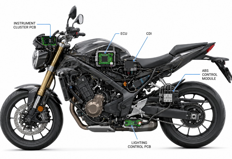
What Are the Main Circuit Boards Found in Motorcycles?
A motorcycle normally uses several specialized electronic modules rather than one PCB controlling the entire vehicle. Some systems have dedicated circuit boards, while manufacturers may combine several functions into one module to reduce wiring, connectors, weight, and installation space.
| Circuit Board | Main Function | Typical Application |
|---|---|---|
| ECU PCB | Engine management and fuel injection | Fuel-injected motorcycles |
| CDI PCB | Ignition control | CDI-equipped motorcycles |
| Instrument Cluster PCB | Speed, RPM, warnings, and display | Modern motorcycles |
| ABS Control PCB | Wheel-speed processing and brake control | ABS-equipped motorcycles |
| Lighting Control PCB | LED driving and lighting protection | LED lighting systems |
| Body Control PCB | Accessories, security, and switching | Higher-spec motorcycles |
| BMS PCB | Battery monitoring and protection | Electric motorcycles |
| Motor Controller PCB | Motor torque and speed control | Electric motorcycles |
| DC-DC Converter PCB | Voltage conversion | Electric motorcycles |
| Charger Control PCB | Battery charging | Electric motorcycles |
A simple commuter motorcycle may use only a few major electronic modules. Premium touring, sport, adventure, and electric motorcycles can use several controllers connected through a vehicle communication network.
This is why what kind of circuit boards are found in motorcycles varies significantly between motorcycle platforms. Engine type, braking technology, display features, security systems, and electric powertrain architecture all affect the final electronic configuration.
Where Are Circuit Boards Located on a Motorcycle?
Motorcycle PCBs are normally enclosed inside protective electronic modules rather than exposed directly to the environment. Mounting positions are influenced by wiring length, temperature, vibration, moisture exposure, available space, cooling, and service access.
| Location | Typical Circuit Boards |
|---|---|
| Under the seat | ECU, immobilizer, communication module |
| Behind side covers | ECU, CDI, accessory controller |
| Inside the instrument cluster | Dashboard PCB |
| Near the ABS modulator | ABS control electronics |
| Inside the headlamp | LED driver PCB |
| Near handlebar controls | Switch or interface PCB |
| Inside the battery pack | BMS PCB |
| Near the electric motor | Motor controller or inverter |
| Near the traction battery | DC-DC converter and charger electronics |
Placement involves a balance between electrical and environmental requirements. Engine-control electronics need practical connections to sensors and actuators, but they should be kept away from excessive exhaust or engine heat. Modules installed near the front or lower areas of a motorcycle may also require stronger protection from water and road contamination.
Electric motorcycles introduce additional layout constraints. High-current paths should remain reasonably short, while sensitive control circuits need suitable separation from higher-voltage power sections. Cooling also becomes more important around inverters, chargers, motor controllers, and DC-DC converters.
Location therefore helps explain what kind of circuit boards are found in motorcycles and why environmental requirements can differ even between boards on the same motorcycle.
How Do Motorcycle ECU and CDI Circuit Boards Differ?
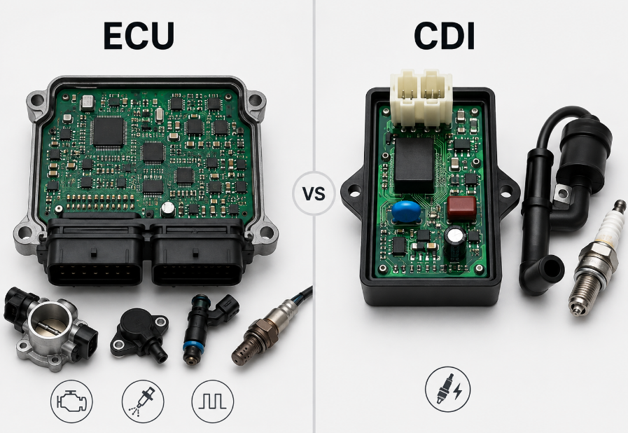
An ECU and a CDI can both influence ignition, but they perform very different roles. The ECU provides broad engine management, while a CDI is mainly responsible for ignition control.
| Feature | ECU PCB | CDI PCB |
|---|---|---|
| Primary Function | Complete engine management | Ignition control |
| Fuel Injection | Usually controlled | Normally not controlled |
| Ignition Timing | Controlled | Controlled |
| Sensor Processing | Multiple engine sensors | More limited |
| Processing Complexity | High | Lower |
| Diagnostics | Common | Usually limited |
| Communication | Often supported | Usually minimal |
| Typical Use | Modern EFI motorcycles | Simpler or older ignition systems |
An Engine Control Unit PCB receives information about engine operating conditions and uses it to manage fueling and ignition. Modern ECUs may also coordinate electronic throttle operation, cooling functions, diagnostics, and communication with other vehicle controllers.
A CDI circuit board has a narrower task. It stores electrical energy in a capacitor and releases that energy through the ignition coil at the required time, allowing the spark plug to ignite the air-fuel mixture.
Some motorcycles use transistor-controlled ignition or other electronic ignition architectures. Therefore, ECU, CDI, and ignition-control modules should not automatically be treated as interchangeable when identifying what kind of circuit boards are found in motorcycles.
Which Circuit Boards Are Used in Motorcycle Instrument Clusters and Dashboards?
Modern motorcycle dashboards are embedded electronic systems rather than simple mechanical gauges. Even a basic digital instrument cluster may contain a microcontroller, regulated power supply, signal-conditioning circuits, memory, LED drivers, display drivers, and communication interfaces.
Typical dashboard PCB functions include:
- Vehicle information: Displays speed, engine RPM, fuel level, gear position, temperature, and trip data.
- Warning information: Shows engine, ABS, battery, oil, temperature, and system-status warnings.
- Display control: Drives LCD, TFT, LED indicators, backlighting, and brightness functions.
- Data storage: Stores odometer and selected configuration information.
- Vehicle communication: Exchanges information with the ECU, ABS controller, and other modules.
- Connected functions: Supports Bluetooth, navigation, or smartphone integration on higher-spec motorcycles.
Older motorcycles may use individual wires for different instrument signals. Newer models increasingly exchange data digitally through a shared vehicle network, allowing several controllers to provide information to one display.
A basic cluster may use a conventional rigid PCB, while a full-color TFT dashboard may require multilayer routing, faster processors, external memory, communication transceivers, and multiple power rails.
Instrument electronics are therefore an important part of what kind of circuit boards are found in motorcycles, particularly as mechanical gauges continue to be replaced by digital displays.
How Do ABS and Traction Control Circuit Boards Work in Motorcycles?
ABS and traction control both rely on wheel-speed data, but they intervene in different situations. ABS works mainly during braking, while traction control works mainly during acceleration. Their control electronics continuously evaluate sensor signals and determine whether corrective action is required.
When braking, the ABS control PCB monitors how quickly each wheel slows down. If one wheel begins to decelerate unusually quickly and approaches lockup, the controller commands the hydraulic modulator to adjust brake pressure. By operating valves and the pump, the system helps the wheel continue rotating instead of remaining locked.
Traction control uses similar wheel-speed information to detect excessive driven-wheel slip during acceleration. When rear-wheel slip exceeds the control strategy, the system can work with the ECU to reduce engine torque through electronic throttle adjustment, ignition timing changes, or fuel-control intervention.
More advanced motorcycles may also use an Inertial Measurement Unit (IMU). IMU data provides additional information about motorcycle acceleration and rotational movement, allowing systems such as cornering ABS and lean-sensitive traction control to consider the motorcycle’s dynamic condition rather than relying only on wheel-speed signals.
Safety electronics therefore add another layer to what kind of circuit boards are found in motorcycles, particularly on modern performance and touring motorcycles.
What Circuit Boards Control Motorcycle Lighting and Body Electronics?
Modern motorcycle lighting frequently relies on dedicated electronic boards, especially where high-power LEDs, daytime running lights, adaptive lighting, or electronically controlled indicators are used.
A motorcycle lighting PCB may provide:
- LED current regulation: Maintains stable light output as vehicle voltage changes.
- Voltage conversion: Provides the voltage required by the LED circuit.
- Transient protection: Protects electronics from electrical spikes.
- Reverse-polarity protection: Reduces damage risk from incorrect connections.
- Thermal protection: Reduces output when LEDs or drivers become too hot.
- Fault monitoring: Detects open circuits, short circuits, and abnormal loads.
- Brightness control: Supports dimming and different lighting modes.
Other body-electronics boards may support:
- Keyless start and immobilizer systems
- Alarm and security electronics
- Heated grips and accessory control
- USB charging and power outlets
- Bluetooth and smartphone communication
- GPS and telematics
- Electronic switch modules
Some motorcycles keep these functions in separate modules, while others combine several functions into one body-control unit. Integration can reduce wiring, but it increases PCB complexity because one board may need to handle communication, switching, protection, sensing, and low-voltage logic.
These smaller modules are often overlooked when researching what kind of circuit boards are found in motorcycles, although they account for a growing share of modern motorcycle electronics.
What Circuit Boards Are Found in Electric Motorcycles?
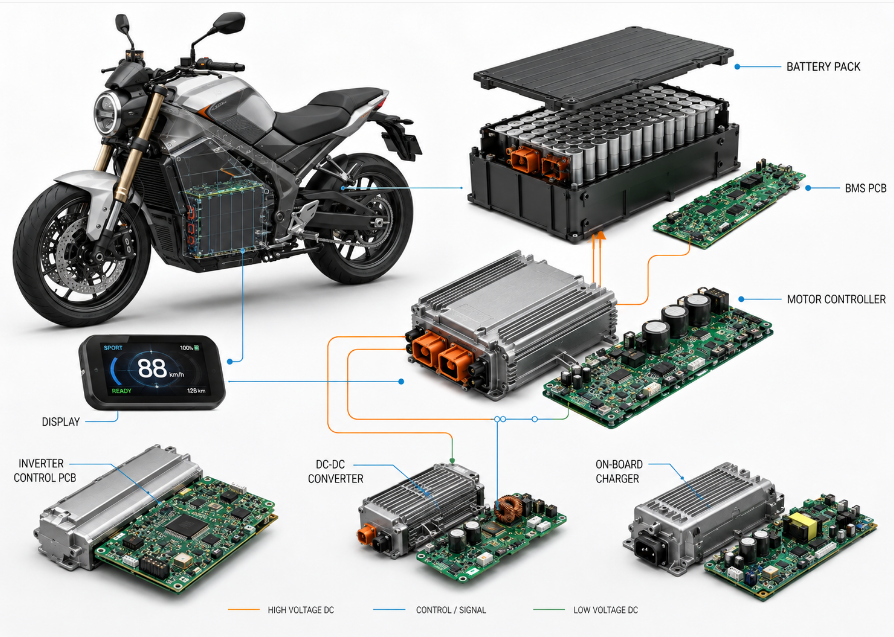
Electric motorcycles retain conventional electronics such as dashboards, ABS, lighting, security, and communication modules. However, the electric drivetrain adds several boards for battery management, motor control, charging, and power conversion.
| Circuit Board | Main Function | Design Focus |
|---|---|---|
| BMS PCB | Battery monitoring and protection | Cell measurement and protection |
| Motor Controller PCB | Motor speed and torque control | High-current switching control |
| Inverter Control PCB | Controls semiconductor switching | Gate control and isolation |
| Vehicle Control Unit PCB | Coordinates vehicle-level functions | System communication and control |
| DC-DC Converter PCB | Supplies lower-voltage electronics | Voltage conversion |
| On-Board Charger PCB | Controls battery charging | Charging and power conversion |
| Display PCB | Displays vehicle and battery information | User interface |
| Telematics PCB | Supports connected functions | GPS, Bluetooth, or cellular communication |
The main difference in an electric motorcycle is the high-voltage traction system. While control circuits typically operate at lower voltages, the battery, inverter, and motor power stage handle much higher voltage and current. The BMS monitors critical battery conditions such as cell voltage, current, temperature, and state of charge.
Motor controllers, inverters, chargers, and DC-DC converters also place stricter demands on PCB design. These circuits require careful control of creepage and clearance, electrical isolation, current sensing, high-current interconnections, thermal management, and fault protection to separate sensitive control electronics from higher-energy power sections.
Electric powertrains therefore significantly expand what kind of circuit boards are found in motorcycles compared with a basic gasoline-powered motorcycle.
Which PCB Types Are Commonly Used in Motorcycle Electronics?
Motorcycle electronics can use several PCB constructions. The appropriate technology depends on current level, routing density, available space, mechanical geometry, and thermal requirements.
| PCB Type | Typical Application | Design Purpose |
|---|---|---|
| Rigid PCB | ECU, ABS, dashboard | General electronic control |
| Multilayer PCB | ECU, TFT display, communication module | Dense routing and internal power/ground planes |
| Flexible PCB | Displays, switches, sensors | Routing through restricted or curved spaces |
| Rigid-Flex PCB | Compact integrated assemblies | Reduced cables and connectors |
| Heavy-Copper PCB | Motor control and power conversion | Higher current carrying capability |
| Metal-Core PCB | High-power LED headlights | Improved heat dissipation |
Among these technologies, rigid FR-4 PCB remains the most widely used for conventional motorcycle electronics. More specialized constructions become useful where packaging, current, or thermal requirements exceed what a standard rigid board can handle efficiently.
This gives another useful way to understand what kind of circuit boards are found in motorcycles: by electronic function, such as ECU or ABS, and by physical PCB construction, such as rigid, flexible, heavy-copper, or metal-core PCB.
What Materials and Construction Are Used for Motorcycle Circuit Boards?
Motorcycle PCB materials should be selected according to the actual electrical and environmental demands of the module. A low-current dashboard board and a high-current motor-control board may both be installed on motorcycles, but their construction requirements are very different.
Common material and construction choices include:
- FR-4 laminate: Widely used for ECU, ABS, dashboard, and body-control electronics because of its electrical insulation, strength, availability, and manufacturing maturity.
- High-Tg FR-4: Suitable where the PCB experiences elevated temperatures or repeated thermal cycling.
- Polyimide: Common in flexible and rigid-flex circuits where bending or compact packaging is required.
- Aluminum-based substrate: Used in high-power LED lighting where efficient heat transfer is important.
- Heavier copper: Supports higher current and reduces conductor resistance.
- Multilayer stackup: Provides dense routing, internal power distribution, and stable ground reference.
- Thermal vias: Transfer heat from power devices into internal copper or a thermal structure.
- Solder mask and surface finish: Protect copper and support reliable PCB assembly.
Copper thickness should match expected current. Signal and communication circuits carry relatively little current, while power-conversion and motor-control sections may require much larger conductor cross-sections.
Layer count also changes with circuit complexity. A simple switch PCB may use two layers, while an ECU or advanced display may require multiple layers for power planes, ground planes, communication interfaces, and dense SMT routing.
Material selection is therefore an important technical part of what kind of circuit boards are found in motorcycles, because application name alone does not define PCB construction.
How Are Motorcycle Circuit Boards Designed for Heat, Vibration, Moisture and EMI?
Motorcycle electronics operate in an environment that combines temperature cycling, continuous vibration, water exposure, road contamination, and electrical noise. These stresses can affect solder joints, connectors, copper traces, power components, and communication signals.
For heat control:
- Increase copper area around power components: MOSFETs, voltage regulators, LED drivers, and power ICs can generate significant heat. Larger copper areas help spread heat and reduce localized hot spots.
- Use thermal vias where heat must move between layers: Thermal vias transfer heat from hot component pads into internal or opposite-side copper.
- Add heat spreaders or metal housings: Motor controllers, chargers, converters, and high-power LED drivers may need a direct thermal path into a metal structure.
- Separate heat-sensitive components: Capacitors, sensors, oscillators, and communication devices should not be placed unnecessarily close to major heat sources.
- Select suitable materials and components: The laminate, connectors, semiconductors, and capacitors should tolerate expected operating temperatures and repeated thermal cycling.
Effective thermal design helps reduce component aging, solder fatigue, and performance drift, not only immediate overheating.
For vibration resistance:
- Support heavy components: Large capacitors, inductors, relays, and connectors can place repeated stress on solder joints.
- Secure board-mounted connectors: Harness movement should not transfer excessive mechanical force directly into PCB solder joints.
- Avoid unsupported tall components: Tall parts move more during vibration and place greater stress on their leads.
- Control PCB flexing: Standoffs and mounting points should distribute mechanical loads without concentrating stress.
- Protect mechanically sensitive components: BGAs and ceramic capacitors should be kept away from areas where the PCB bends significantly.
Vibration damage often develops gradually. A board may pass initial testing but later develop intermittent solder cracks, connector faults, or broken internal connections.
For moisture protection:
- Use sealed housings and connectors: The enclosure provides the first barrier against rain, road spray, dust, and washing water.
- Apply conformal coating where required: Suitable coating can reduce moisture-related leakage and corrosion.
- Use potting or encapsulation in severe environments: Stronger environmental protection may be needed for exposed modules.
- Maintain PCB cleanliness: Ionic residues can attract moisture and increase corrosion or leakage risk.
- Consider condensation: Even sealed housings can experience internal moisture when temperature changes repeatedly.
Moisture protection should be treated as a system-level design issue. Conformal coating cannot compensate for a poorly sealed connector or an enclosure that allows water to collect around the PCB.
For EMI and electrical-transient control:
- Maintain controlled return paths: Switching and high-current signals should have short, predictable current paths.
- Filter power and external signal lines: Ferrites, capacitors, and other filtering components help reduce conducted noise.
- Separate noisy and sensitive circuits: Motor drives, injectors, ignition circuits, and switching regulators should be kept away from low-level analog signals where possible.
- Protect exposed interfaces: Voltage transients from inductive loads or charging-system faults can damage unprotected electronics.
- Use proper grounding and decoupling: Ground structure and local decoupling improve processor, sensor, and communication stability.
Motorcycles contain many noise sources, including ignition coils, alternators, injectors, motors, solenoids, and switching converters. A PCB that works correctly on a bench can still experience communication errors or component damage if EMI and transient protection are inadequate.
Environmental reliability is therefore inseparable from what kind of circuit boards are found in motorcycles.
What Common Circuit Board Failures Occur in Motorcycles?
Motorcycle PCB failures usually result from a combination of mechanical stress, temperature, moisture, electrical overload, component aging, and environmental exposure.
Common failures include:
- Cracked solder joints: Vibration and temperature cycling can weaken joints around connectors and heavier components.
- Corrosion: Moisture and contamination can attack copper, vias, component leads, and connector contacts.
- Power-component failure: MOSFETs, regulators, and drivers can fail because of overheating, excessive current, or electrical transients.
- Damaged copper traces: Excessive current or corrosion can create open circuits and localized overheating.
- Via damage: Mechanical and thermal stress can produce intermittent internal connections.
- Connector failure: Oxidized, loose, or overheated terminals can interrupt power, signals, or communication.
- Water ingress: Moisture can produce corrosion, leakage current, and short circuits.
- Transient damage: Reverse polarity, charging-system faults, and inductive spikes can damage protection and power circuits.
Some failures are intermittent rather than permanent. A cracked solder joint may work while the motorcycle is stationary but lose contact under vibration. Corrosion can also increase electrical resistance gradually rather than causing an immediate failure.
A critical diagnostic point is that an electronic fault does not automatically prove the PCB is defective. Weak batteries, poor grounds, damaged wiring, faulty sensors, loose connectors, and unstable charging systems can create symptoms that resemble a failed control board.
Understanding failure mechanisms adds practical value to what kind of circuit boards are found in motorcycles, especially when troubleshooting electronic problems.
How Can You Identify a Faulty Circuit Board in a Motorcycle?
A suspected motorcycle PCB should not be judged from symptoms alone. Problems such as hard starting, warning lights, intermittent displays, ABS faults, communication errors, or loss of ignition can also come from external wiring, power, sensors, or actuators.
A practical diagnostic sequence is:
- Check the battery and charging voltage.
Confirm that battery voltage remains stable during key-on, cranking, and normal operation. Low voltage can cause controllers to reset, while excessive charging voltage can damage electronic components. - Verify power, fuses, and ground connections.
Confirm that the suspected module receives the correct power supply. Check grounds for corrosion, looseness, excessive resistance, or voltage drop. - Inspect connectors and the wiring harness.
Look for bent pins, loose terminals, corrosion, overheating, damaged seals, rubbed insulation, and broken conductors. - Read diagnostic trouble codes and live data.
Fault codes can narrow the problem to a sensor circuit, actuator, communication line, power supply, or specific controller. Live data can also show whether sensor readings remain plausible during operation. - Test related sensors and actuators.
Check devices associated with the fault before replacing the controller. Depending on the system, this may include crank sensors, wheel-speed sensors, throttle sensors, ignition coils, injectors, pumps, or solenoids. - Check communication between modules.
On networked motorcycles, verify whether the suspected module communicates correctly. Lost communication may result from an internal fault, but it can also come from poor power, grounding, connectors, or network wiring. - Inspect the PCB when external causes have been excluded.
Look for burned components, cracked solder joints, corrosion, damaged traces, overheated connectors, or water ingress. - Use dynamic measurements for intermittent faults.
A multimeter is suitable for basic voltage, resistance, and continuity checks, while an oscilloscope may be required for CAN signals, ignition waveforms, injector pulses, or switching circuits.
The final diagnosis should rely on several pieces of evidence rather than one fault code. Stable power, reliable wiring, correct sensor behavior, normal communication, and measurable PCB abnormalities provide much stronger evidence of an actual circuit-board failure.
Electric motorcycle battery packs, inverters, and motor controllers can contain hazardous high voltage even after the motorcycle is switched off. Internal testing should follow appropriate high-voltage isolation and safety procedures.
FAQs About Motorcycle Circuit Boards
Q1: Is a motorcycle electronic module the same as a PCB?
A1: No. A PCB is the circuit board inside the module. The complete module can also include connectors, an enclosure, seals, firmware, and thermal components. An ECU, for example, is a complete electronic assembly rather than only the bare PCB.
Q2: Can one motorcycle module contain more than one PCB?
A2: Yes. Complex modules may contain multiple interconnected PCBs to separate control, power, display, or communication circuits. Stacked boards or daughterboards are sometimes used when space is limited or different circuit sections have different design requirements.
Q3: Are motorcycle circuit boards interchangeable between different model years?
A3: Not always. Boards that look similar can use different firmware, pin assignments, calibration data, communication settings, or hardware revisions. Compatibility should be checked by part number and technical specification rather than appearance alone.
Q4: Why can a replacement motorcycle ECU require immobilizer pairing?
A4: Some motorcycles link the ECU with the coded key, immobilizer, dashboard, or security controller. A replacement ECU may therefore require pairing or programming before the motorcycle will start normally.
Q5: What communication interfaces can motorcycle electronics use?
A5: Modern motorcycles commonly use CAN bus, while other designs may use LIN, UART, proprietary communication, or dedicated analog and digital signals. The interface depends on the system architecture and the devices being connected.
Q6: Can aftermarket electronics interfere with motorcycle control boards?
A6: Yes. Poorly installed accessories can introduce voltage drops, electrical noise, excessive current draw, or network communication problems. Auxiliary electronics should therefore use suitable fusing, grounding, and transient protection.
Q7: What information is required to manufacture a custom motorcycle PCB?
A7: Useful manufacturing data includes Gerber or ODB++ files, drill files, stackup requirements, copper thickness, BOM, assembly drawings, centroid data, and test requirements. Operating voltage, current, temperature, vibration, and enclosure conditions should also be defined.
Q8: How should a prototype motorcycle PCB be validated?
A8: Validation should go beyond checking whether the PCB powers on. Testing should cover supply variation, operating load, temperature, vibration, communication, transient behavior, and relevant fault conditions before extended road testing.
Q9: Which standards can apply to motorcycle circuit boards?
A9: Applicable requirements depend on the PCB function and market. They can include PCB workmanship, electronics assembly, environmental testing, electrical compatibility, and manufacturer-specific requirements. Safety-related electronics generally require more extensive verification.
Q10: What should be confirmed before ordering motorcycle PCBs in volume?
A10: Before mass production, confirm the PCB stackup, copper requirements, components, connectors, environmental protection, assembly process, test coverage, and acceptance criteria. Prototype issues should be resolved before the design is released for volume production.
Conclusion
So, what kind of circuit boards are found in motorcycles? Depending on the motorcycle, the electronic system may include ECU PCBs, CDI boards, dashboard PCBs, ABS controllers, lighting electronics, body-control modules, BMS boards, motor controllers, charger boards, and DC-DC converters. Each application requires a PCB construction that matches its electrical load, operating temperature, vibration exposure, moisture protection, communication requirements, and available space.
For a new motorcycle electronics project, PCB selection should be based on the actual circuit requirements, mechanical environment, reliability targets, prototype validation, and production volume rather than the application name alone. If you are developing a motorcycle PCB or PCBA for prototype development, OEM/ODM production, custom manufacturing, or volume production, contact our team for technical support and a quotation.
You may also like



Tags: Motorcycle Circuit Boards, Motorcycle Electronics, Motorcycle PCB, what kind of circuit boards are found in motorcycles