





UART vs SPI is a choice between a simple asynchronous point-to-point link and a faster clocked interface for on-board peripherals. Choose UART when the design needs few signals, service access, or an external serial transceiver. Choose SPI when an MCU must exchange data quickly with converters, displays, memory, or sensors on the same assembly.
Neither interface has a universal speed, distance, or power advantage. The result depends on the selected devices, physical layer, frame format, edge rate, routing, firmware, and test method.
Logic-level UART is not the same physical layer as RS-232 or RS-485. Compare the actual transceivers, voltage thresholds, routing, timing, and test limits instead of assigning cable performance to the UART peripheral itself.
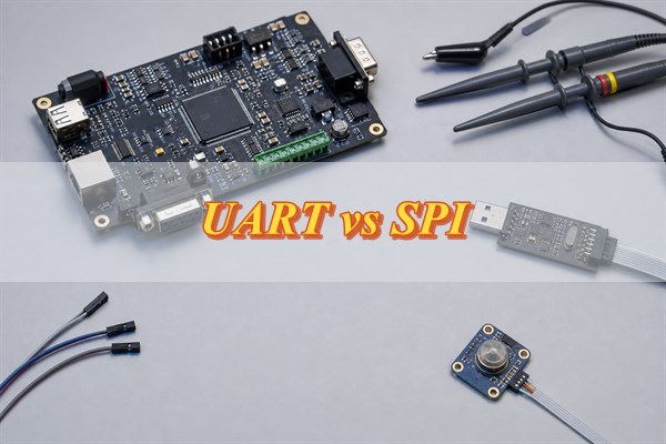
UART vs SPI at a Glance: Which Interface Fits Your Design?
Choose UART for a simple two-device link or service port; choose SPI for fast, short, controller-to-peripheral communication on one PCB. The first decision should use the required payload rate, pin budget, number of peripherals, physical distance, error-handling plan, and debug access. Nominal clock frequency alone is not enough.
| Decision Factor | UART | SPI | Engineering Decision |
| Timing method | Asynchronous; both ends agree on baud and frame format | Synchronous; controller supplies the serial clock | Use SPI when a shared clock simplifies high-rate sampling; use UART when a clock line is undesirable |
| Typical signals | TX, RX, and ground; optional RTS/CTS | SCLK, MOSI, MISO, chip select, and ground | UART saves pins for one link; SPI chip-select count grows with conventional multi-peripheral topology |
| Payload efficiency | Reduced by start, stop, and optional parity bits | Often near one payload bit per clock during an active transfer, but commands and gaps still count | Calculate complete transactions instead of comparing baud with SCLK directly |
| Distance | Logic-level UART is normally local; transceivers can support cables and harsher links | Normally short and board-level unless buffering or another physical layer is engineered | Do not assign a distance without voltage, cable, ground, edge-rate, and receiver limits |
| Error handling | Framing status and optional parity may expose some faults | No universal protocol-level error check | Add application-level checks when corrupted or missing data can create a system hazard |
| Common applications | Debug console, GNSS module, modem, bootloader, controller-to-controller link | ADC, DAC, flash, display, sensor, codec, high-rate peripheral | Confirm the exact peripheral interface and timing requirements before schematic release |
I2C may be preferable when many low-to-moderate-rate peripherals must share two signals, while CAN or RS-485 may be more suitable for robust multi-node cabling. Change the interface architecture when distance, arbitration, fault containment, or connector exposure dominates the requirement.
How Do UART and SPI Transfer Data?
UART reconstructs each frame from an agreed baud rate, while SPI shifts data against a controller-generated clock. Both are normally MCU hardware peripherals, although low-rate software implementations are possible.
UART sends a start bit, payload bits, optional parity, and one or more stop bits. An 8N1 frame carries 8 payload bits in 10 transmitted bits. Because the receiver uses its own timing reference, both endpoints must agree on the frame and baud settings.
In SPI, the controller asserts chip select, supplies SCLK, sends data on MOSI, and receives data on MISO. CPOL defines the idle clock level; CPHA defines the sampling relationship. A CPOL or CPHA mismatch can sample every bit on the wrong edge.
- UART configuration: Record baud, payload length, parity, stop bits, idle polarity, voltage threshold, and any flow-control signals.
- SPI configuration: Record SCLK limit, CPOL, CPHA, bit order, word length, chip-select behavior, command format, and turnaround timing.
- Firmware boundary: Confirm FIFO depth, DMA availability, interrupt latency, buffer ownership, timeout behavior, and recovery after incomplete transfers.
- Electrical boundary: Verify that both endpoints use compatible I/O voltage and threshold levels; a matching protocol setting does not correct an electrical mismatch.
UART vs SPI Speed: Clock Rate, Frame Overhead, and Effective Throughput
SPI generally delivers higher payload throughput, but compare completed payload per unit time rather than SCLK with baud. UART spends time on start, stop, and optional parity bits. SPI instead loses useful time to command bytes, addresses, dummy clocks, chip-select gaps, and software latency.
For UART, a practical first calculation is:
Payload efficiency = payload bits / total frame bits.
An 8N1 frame contains 8 payload bits within 10 transmitted bits, so its theoretical payload efficiency is 80%. At 115,200 baud, the ideal continuous payload rate is 115,200 × 8 / 10 = 92,160 bit/s, or 11,520 bytes/s. Buffer gaps, flow control, operating-system scheduling, error recovery, and higher-layer framing reduce the sustained result.
For SPI, calculate every clocked field and every unclocked interval:
Transaction time = total clocked bits / SCLK frequency + chip-select and inter-transfer gaps.
If a transaction needs an 8-bit command, 16-bit address, 8 dummy clocks, and 256 payload bits, it consumes 288 clock periods. At 10 MHz, clocking takes 28.8 microseconds before chip-select, firmware, and peripheral-ready delays. A 10 MHz SCLK therefore does not guarantee 10 Mbit/s of application payload.
How Do UART and SPI Differ in Pins, Wiring, and Device Topology?
UART uses fewer signals for one point-to-point link; conventional SPI shares data and clock lines but usually needs one chip select per peripheral. Include grounds, enables, interrupts, resets, level shifters, connectors, and test points in the real pin and routing count.
A full-duplex UART connection crosses TX to RX and RX to TX between two endpoints. RTS and CTS can provide hardware flow control where a receiver may be unable to accept a continuous stream. A service header may expose only TX, RX, and ground, but the header voltage and pin orientation must be documented to prevent damage from an incompatible adapter.
A four-signal SPI bus commonly shares MOSI, MISO, and SCLK while routing a separate chip select to each peripheral. This makes controller-to-many-peripheral communication convenient, but every added branch changes capacitance and stub behavior. MISO also requires special attention: nonselected peripherals must release the line, or two outputs can contend.
- Pin-budget check: Count all chip selects, interrupts, ready/busy lines, resets, enables, flow-control pins, and test access.
- Topology check: Draw the controller, every peripheral, each branch point, connector transition, and return path before routing.
- Voltage check: Place level translation according to signal direction and verify power-off behavior at both sides.
- Contention check: Confirm MISO high-impedance timing from each peripheral datasheet before sharing the line.
Which Is More Reliable Over Distance and Electrical Noise: UART or SPI?
Neither UART nor SPI has a universal distance rating. The limit comes from the physical layer, edge rate, interconnect, ground offset, receiver thresholds, and timing margin—not the protocol name.
- Logic-level UART: Keep ground offset, I/O voltage, thresholds, and noise within the endpoint limits for a board trace or short harness.
- Externally exposed UART: Use an appropriate physical-layer transceiver and protection strategy for longer cables or harsher environments.
- SPI interconnect: Treat cable delay, signal skew, capacitive loading, connector discontinuities, and ringing as sampling-margin risks.
- Clock-rate experiment: If lowering SCLK hides the failure, use that result as a timing-margin clue rather than a final correction.
- Distance limit: Set it from receiver thresholds, setup and hold margin, overshoot and undershoot limits, ground offset, return conductors, and expected noise.
UART vs SPI Power Consumption: What Changes at the System Level?
Compare energy per completed transaction, not wire count or instantaneous current alone. SPI may switch more lines but finish sooner; UART may use fewer signals yet keep the MCU and peripheral active longer.
Use the same payload and operating condition. Measure supply current before, during, and after the transfer, then integrate it over time. Include level shifters, transceivers, pull resistors, isolators, clock sources, and peripheral wake time.
- Measurement boundary: Define which rails and devices are included in the power result.
- Workload boundary: Use the same payload size, update interval, error rate, and retry policy.
- Firmware boundary: Compare polling, interrupt, FIFO, and DMA implementations because CPU awake time can dominate.
- Sleep boundary: Include wake-up latency and the time required for the interface and peripheral to become usable.
When Should You Choose UART, and When Is SPI the Better Option?
Choose UART for simplicity, service access, or a transceiver-based external link; choose SPI for short on-board links that need higher throughput and controller-driven timing. Base the choice on written requirements rather than familiarity or a headline datasheet rate.
- Choose UART: The design has two endpoints, modest sustained throughput, limited pins, a debug console, or a transceiver-based external link.
- Choose SPI: The design connects an MCU to fast on-board ADCs, DACs, flash, displays, codecs, or sensors with compatible timing.
- Reconsider UART: Multiple nodes need arbitration, the link requires a shared bus, or the receiver cannot tolerate unbounded stream loss.
- Reconsider SPI: The route crosses a long cable, chip-select count is excessive, peripherals cannot release MISO correctly, or clock skew consumes the timing budget.
- Escalate the review: Safety, machine control, field wiring, isolation, or fault containment requires a physical layer and application protocol designed for those conditions.
Before schematic approval, document payload rate, maximum latency, topology, voltage, distance, connector exposure, noise, recovery behavior, boot state, firmware ownership, and required production evidence.
How Do Trace Length, Edge Rate, Loading, and Return Paths Limit UART and SPI?
PCB routing risk follows signal rise and fall time more directly than baud or SCLK alone. Even a low-rate interface can behave as a transmission line when a CMOS output switches quickly. Review propagation delay, branches, load capacitance, reference planes, vias, connectors, and receiver thresholds.
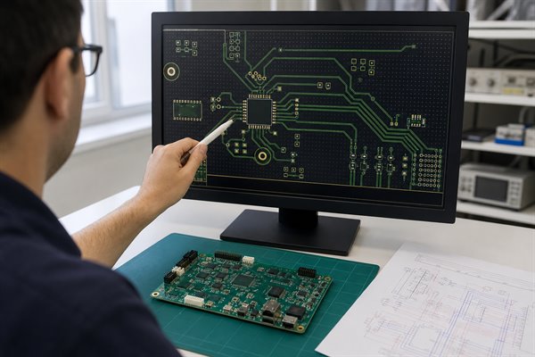
- Preserve the return path: Keep SCLK and other fast edges over an uninterrupted reference plane and away from plane splits.
- Control branches and stubs: Place the controller and fast peripherals for short, direct routes, especially on shared SPI signals.
- Support layer changes: Add a nearby return-path transition when a via changes the signal reference.
- Use damping from evidence: Add a source-series resistor near the driver only when simulation or measurement shows ringing. The value is implementation-specific.
- Model every interface element: Include level shifters, isolators, connectors, and test pads in the UART and SPI PCB layout review.
- Release measurable constraints: Trace each routing limit to a selected-device requirement and a verification method.
Which PCB Layout Errors Cause UART Framing Faults or SPI Signal Integrity Failures?
UART failures usually corrupt frames; SPI failures usually corrupt individual transactions. UART symptoms include garbled characters, framing or parity errors, and missing bytes. SPI symptoms include wrong bits, repeated commands, invalid reads, and failures that disappear at a lower clock rate.
- Check UART settings: Confirm common ground, I/O voltage, idle polarity, baud, word length, parity, and stop bits.
- Measure UART at the receiver: Compare TX at the source with RX at the destination. Look for slow edges, crosstalk, ground shift, and threshold crossings near the sampling point.
- Check SPI settings: Confirm CPOL, CPHA, word length, bit order, chip-select setup and hold, and the peripheral’s data-valid delay.
- Measure SPI at the receiver: Probe SCLK and data at the peripheral pins. Ringing can create an extra clock, while late data can violate setup or hold time.
- Check the shared MISO line: Verify that every nonselected peripheral releases MISO before another device drives it.
Do not treat a clean digital decode as proof of electrical margin. Use the following sequence to separate a configuration error from a routing, loading, or timing problem.
- Reproduce the fault: Use the target voltage, temperature, firmware load, and interface rate.
- Capture both endpoints: Measure controller-side and receiver-side signals with a defined probe and ground connection.
- Test the timing margin: Reduce baud or SCLK without changing other conditions; improvement is a clue, not a final fix.
- Check device limits: Compare the capture with datasheet thresholds, setup, hold, data-valid, and chip-select timing.
- Isolate the fault class: Separate configuration faults from electrical faults by changing one controlled variable at a time.
- Verify the correction: Fix the root cause, then repeat the test at nominal and boundary conditions.
How Can UART and SPI Interfaces Be Validated from Prototyping to Production?
Validation must connect schematic requirements to receiver-pin waveforms and a repeatable production functional test. One successful logic-analyzer decode does not prove voltage margin, boundary-condition operation, or long-term data integrity.
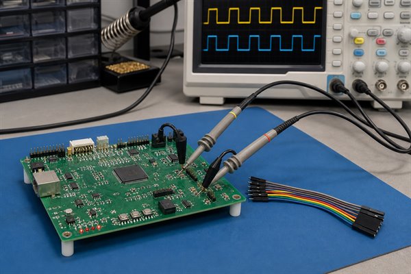
- Define the requirement: Record the payload, rate, frame or transaction format, voltage, topology, and pass/fail behavior.
- Provide test access: Add ground, TX/RX, SCLK, MOSI, MISO, and chip-select test points without creating harmful stubs.
- Control probe loading: Select probes whose input capacitance and ground connection do not materially change the waveform.
- Configure UART decode: Use the actual baud, data bits, parity, stop bits, polarity, and threshold.
- Configure SPI decode: Use the actual CPOL, CPHA, word length, bit order, chip-select framing, and threshold.
- Measure at the receiver: Check voltage levels, ringing, edge rate, setup, hold, data-valid delay, and chip-select timing at the receiving pins.
- Exercise boundary behavior: Test minimum and maximum payloads, repeated transfers, idle-to-active transitions, reset, power cycling, and fault recovery.
- Retain test evidence: Record error counters, returned data, timeouts, and waveforms under defined boundary conditions.
- Transfer checks to production: Define fixture connections, firmware commands, expected responses, limits, and traceable records.
IPC-A-610 provides visual acceptance criteria for completed electronic assemblies, while J-STD-001 covers soldering materials, methods, process control, and acceptance requirements. Neither standard proves UART baud tolerance, SPI timing margin, firmware correctness, or error-free data transfer. These require product-specific electrical and functional tests.
FAQs About UART vs SPI
Q1: Can UART and SPI run at the same time on one microcontroller?
A1: Yes, if the MCU provides separate peripherals, pins, clocks, DMA channels, and interrupt capacity. Simultaneous operation can still create bus, memory, or CPU contention, so validate buffer service time and worst-case latency under the real firmware workload.
Q2: Can a UART-to-SPI bridge replace firmware changes?
A2: A bridge can translate transfers, but it cannot automatically reconcile different command models. Buffer size, latency, flow control, SPI mode, chip-select behavior, error reporting, and reset handling must match the application before the bridge is approved.
Q3: Can SPI peripherals with different modes share one controller?
A3: Yes, if the controller can reconfigure CPOL, CPHA, clock rate, and word format before selecting each peripheral. Keep every chip select inactive during reconfiguration and verify that shared MISO devices release the line.
Q4: Do UART or SPI signals require pull-up resistors?
A4: Neither interface universally requires pull-ups. A particular device may recommend a pull resistor for chip select, reset, MISO, or an idle state. Follow the selected device datasheets and check leakage, power sequencing, and contention.
Q5: Can USART hardware communicate with SPI devices?
A5: Only when the specific USART supports a compatible synchronous mode and timing behavior. Check clock polarity, phase, bit order, chip-select generation, word length, and receive timing. The peripheral name alone does not guarantee SPI compatibility.
Q6: Can DMA improve UART or SPI performance?
A6: DMA can reduce CPU service overhead and make transfer timing more consistent. It does not correct electrical faults, insufficient bus bandwidth, buffer overruns, or an invalid peripheral transaction format.
Q7: Must chip select remain active for an entire SPI transaction?
A7: Follow the peripheral’s transaction definition. Some devices require chip select to remain active across command, address, dummy, and data phases; releasing it early may reset the command state.
Q8: Can UART or SPI pass through a digital isolator?
A8: Yes, but propagation delay, channel direction, jitter, startup state, voltage, and data rate must fit the interface. SPI return-path delay can consume a large part of the sampling budget, so use an isolator designed for the required topology.
Q9: Should unused UART or SPI pins be left floating?
A9: Do not assume floating is safe. Configure unused MCU pins to a documented state and follow peripheral recommendations for chip select, reset, clock, and data inputs. An uncontrolled pin can increase current or trigger unintended commands during startup.
Q10: What interface information should be included in a PCBA quotation package?
A10: Provide the schematic, interface voltage, pin map, programming state, test points, test command, expected response, limits, and retained evidence. Also identify any adapter, fixture, cable, firmware image, or golden unit required for functional testing.
Conclusion
Use UART for simple point-to-point communication and service access; use SPI for faster on-board peripheral transfers when clock and routing margins are controlled. Decide from payload throughput, pins, device count, distance, electrical conditions, recovery, and test access. Verify the receiver-pin waveform and complete transaction rather than relying on nominal ratings.
Contact EBest Circuit at sales@bestpcbs.com for a PCB or PCBA quotation. Please submit Gerber or ODB++ files, BOM, quantity, stackup, assembly requirements, firmware or programming files, and functional-test requirements so the engineering team can review manufacturability and quotation inputs.
You may also like








Tags: UART and SPI testing, UART vs SPI PCB layout, UART vs SPI speed, UART vs SPI wiring