





The continuity setting is usually marked by a sound-wave or buzzer icon, often beside a diode symbol. It checks for a low-resistance path between two probe points. On a bare PCB, that path may run through a trace, via, pad, or plated hole. Once components are fitted, current can find parallel routes, so a beep by itself does not prove that the board is healthy or shorted.

Before trusting a result, confirm the active mode, short the probes to prove the leads, and choose test points from known circuit data. Then compare both the tone and displayed value with the expected path. The same board can read differently in continuity, resistance, and diode modes because the meter does not test it in the same way.
What Is the Symbol for Continuity on a Multimeter?
The symbol for continuity on a multimeter is normally a sound-wave, speaker, or buzzer-shaped icon. It represents the audible tone produced when measured resistance falls below the instrument’s continuity threshold. Many meters combine this icon with the diode-test symbol on one rotary-switch position.
Continuity means that an electrical path is complete. The meter applies a small test stimulus, estimates the resistance between its probes, and sounds a tone when the result meets its programmed rule. The tone is useful on a crowded PCB because the technician can watch the probe tips instead of looking back and forth at the display.
The exact icon is not universal. A meter may show curved sound waves, a small speaker, a musical-note-like mark, or a CONT label. Match the dial icon to the function table in the meter’s manual before testing.
What Does the Symbol for Continuity on a Multimeter Look Like?
The most common continuity test symbol resembles several curved sound waves radiating from a point. It may appear alone, above a secondary-function label, or beside a diode circuit symbol. Color coding can indicate that a button is required to activate it.
| Presentation | Visual Cue | Typical Activation | Best Verification |
| Dedicated position | Sound waves or speaker icon | Turn the selector directly to the icon | Short the probes and confirm a stable tone |
| Shared with diode mode | Sound waves printed beside a diode symbol | Use SELECT, FUNC, or MODE to switch functions | Check whether the display shows continuity or diode mode |
| Secondary colored function | Icon matches a colored button label | Press the matching secondary-function button | Follow the model-specific manual |
| Text-based display | CONT, buzzer, or audible indicator | Select through an on-screen menu | Confirm the active mode before probing the PCB |
Color alone is a poor guide. Red, yellow, blue, and white labels do not carry the same meaning across brands. On a crowded dial, even a speaker-like mark can be confused with capacitance or another secondary function, so confirm the display state after turning the selector.
Why Does the Continuity Symbol Differ Between Multimeter Models?
Continuity symbols differ because manufacturers organize functions, displays, and controls differently. There is no single front-panel layout that every handheld and bench multimeter must use. A compact meter may combine several functions at one position, while a bench instrument may use a menu key.
The intended job also shapes the interface. A field electrician may value a fast, loud tone and controls that work with gloves. An electronics technician may need an adjustable threshold, a latch for brief interruptions, or a visual indication for a quiet bench. Entry-level meters often group resistance, diode, and continuity under one selector position.
The icon is only the visible difference. Response time, open-circuit voltage, test current, latching behavior, and beep threshold can also change from one model to another. That is why two meters may disagree about the same PCB path without either meter being faulty.
Where Is the Continuity Symbol Located and Why Is It Shared with Diode Mode?
The continuity symbol is usually located around the rotary dial near resistance and diode functions. Manufacturers often implement these modes with related resistance and test-current circuitry, so combining their controls saves selector positions and front-panel space. A SELECT or MODE button commonly cycles between them.
On a shared position, the first function after turning the dial may not be continuity. The display may show a diode icon, an ohm symbol, or a sound-wave indicator. Press the function button until the sound-wave indicator appears, then short the probes to verify the selected function.
Check the sockets before touching the board. On most handheld meters, the black lead goes to COM and the red lead to the voltage/resistance input. The high-current socket is not the normal continuity input. A lead left in the wrong socket can invalidate the check and become hazardous when the meter is used for a later measurement.
How Does Continuity Mode Work and What Resistance Triggers the Beep?
Continuity mode applies a small test stimulus and beeps when the measured path meets the meter’s programmed low-resistance rule. There is no universal resistance value that triggers every multimeter. The threshold, timing, and tone behavior must be confirmed in the instrument specifications.
Manufacturer examples show the range of possible behavior. Some handheld meters use a threshold around several tens of ohms; a Fluke instructional example describes a tone at approximately 40 Ω or less on a specified range. Keysight documents a bench meter with a 10 Ω default threshold that can be adjusted from 1 Ω to 1000 Ω. These are model examples, not values to apply to every meter.
A generous threshold makes broken-wire searches quicker, but it can confuse PCB diagnosis. A resistor, coil winding, protection network, or parallel route may satisfy the beeper without creating a direct copper short. The opposite problem also occurs: a damaged contact or cracked via may beep under the meter’s small test current yet fail when the circuit carries its operating load.
Response time matters when the fault is intermittent. Some meters latch a brief change, while others wait for the resistance to remain below the threshold. Flexing or tapping a board may expose a loose connection, but only do so when the assembly and diagnostic procedure allow it.
How Is Continuity Mode Different from Resistance and Diode Test Modes?
Continuity mode makes a rapid pass/fail judgment, resistance mode provides a numeric value, and diode mode evaluates a semiconductor junction in one direction. These functions may share circuitry, but they answer different diagnostic questions.
| Mode | Primary Question | Typical Output | PCB Limitation |
| Continuity | Is the path below the programmed resistance threshold? | Beep plus a resistance or status display | Parallel paths can create a tone that is not a copper short |
| Resistance | What resistance does the meter see between these points? | Numeric value in Ω, kΩ, or MΩ | The reading includes every conductive path between the probes |
| Diode test | What forward voltage appears across a junction at the meter’s test current? | Forward-voltage reading, often in volts | Polarity and surrounding components strongly affect the result |
For a bare trace, start with continuity for speed, then switch to resistance if the actual value matters. On an assembled board, diode mode can help compare semiconductor paths or power rails with a known-good board. None of these readings replaces the schematic, because the meter sees every available in-circuit path.
A marginal solder joint may pass a low-current bench check and open later under vibration, heat, or load. Continuity therefore answers a narrow electrical question at the time of measurement; it does not certify the joint’s mechanical strength or service life.
Which Safety Rules and Testing Limits Apply Before Using Continuity Mode?
Continuity testing should be performed on a de-energized circuit after stored energy has been safely discharged. Never assume that selecting the buzzer mode makes an energized system safe. Verify the absence of hazardous voltage with an appropriate method and correctly rated equipment before touching conductors.
- Remove power: Disconnect external supplies, batteries, chargers, and signal sources that could energize the board.
- Discharge stored energy: Follow the equipment procedure for capacitors, power modules, and high-voltage sections; do not create an uncontrolled short with a probe.
- Inspect the meter: Check the housing, fuse status, leads, insulation, probe guards, input sockets, and selector operation.
- Respect ratings: Use the meter, leads, and accessories only within their stated voltage, current, and measurement-category limits.
- Protect the assembly: Apply ESD controls and avoid slipping probe tips across adjacent fine-pitch pads.
- Isolate uncertain paths: Remove or lift a component only under an approved rework process when in-circuit networks prevent a conclusive result.
IEC 61010-2-033:2023 covers safety requirements for hand-held multimeters capable of measuring mains voltage. A compliance mark does not override the meter manual, accessory ratings, or the site’s electrical-safety procedure. Operator safety and PCB electrical acceptance are separate questions.
IPC-9252B describes netlist-based electrical testing concepts for unpopulated printed boards, including continuity between intended points and isolation between different nets. IPC currently lists this document as no longer maintained, although a drawing or customer contract may still reference it. Confirm the controlling revision and acceptance criteria for each order. A handheld continuity check is a diagnostic tool, not a substitute for contractual bare-board electrical testing.
How Do You Set and Verify a Multimeter for a Continuity Test?
Set up the meter by removing circuit power, connecting the leads correctly, selecting continuity mode, and proving the test path before touching the PCB. A short probe check identifies a wrong mode, damaged lead, poor socket connection, or unexpected lead resistance before it becomes a false board diagnosis.
- De-energize the circuit. Disconnect every known source and discharge stored energy using the equipment’s approved procedure.
- Inspect the work area. Stabilize the PCB, provide sufficient light and magnification, and use ESD protection where required.
- Connect the test leads. Insert the black lead into COM and the red lead into the voltage/resistance input specified by the meter.
- Select continuity mode. Turn the dial to the sound-wave position or use SELECT, FUNC, or MODE until the continuity indicator appears.
- Short the probes together. Confirm a prompt tone and observe the displayed resistance. The value includes the probes and their contacts.
- Record the lead baseline. If the meter supports a relative function, use it according to the manual; otherwise subtract the stable lead resistance only when that calculation is appropriate.
- Choose verified test points. Use the schematic, PCB data, netlist, or known connection instead of guessing from visual proximity.
- Probe without slipping. Hold both tips steadily, note the tone and numeric reading, then repeat from a different accessible point when the result is important.
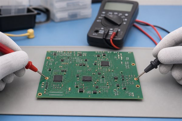
Fine insulated needle probes or micro-hooks give better control around closely spaced pads. Do not puncture solder mask unless the approved procedure permits damage to the finish. Designed test pads, connector pins, and exposed component pads usually give cleaner, repeatable contact.
What Do a Beep, No Beep, 0 Ω, OL and Unstable Readings Mean?
Each indication describes what the meter detects at that moment, not the complete health of the PCB. Interpret the tone together with the resistance value, expected net structure, probe baseline, circuit state, and meter threshold.
| Indication | Immediate Meaning | Possible PCB Explanation | Next Check |
| Steady beep | Resistance is below the programmed threshold | Intended copper connection, low-value component, coil, or unintended bridge | Compare the numeric value and netlist expectation |
| No beep | Threshold was not met or continuity mode is inactive | Open trace, high contact resistance, wrong points, or valid higher-resistance path | Check mode, short the probes, and use resistance mode |
| 0 Ω or near 0 Ω | Very low measured resistance within meter resolution | Solid copper path or short, including lead resistance | Measure the shorted-probe baseline and inspect parallel paths |
| OL or open indication | Reading exceeds the active range or no measurable path exists | Intended isolation, cracked trace, via-barrel discontinuity, or poor probe contact | Retest at intermediate points and inspect the contact surface |
| Unstable value | The measured path is changing | Intermittent joint, oxidation, moving probe, capacitor charging, or circuit noise | Stabilize the probes, wait, isolate the path, and repeat |
A displayed 0.0 Ω does not mean the path has literally zero resistance. It means the combined value is below the useful display resolution on that range. Even shorted probes may show a few tenths of an ohm from the leads and their contact points.
OL needs the same circuit context. Between two isolated nets, it may be exactly what the design requires. Across the ends of one intended trace, it points to a problem only after you have confirmed the test points and made reliable probe contact.
Why Can a Multimeter Beep When There Is No True Short Circuit?
A multimeter can beep without a true short because it detects any path below its threshold, including legitimate component and parallel-network paths. The beeper does not know whether the measured conductance comes from copper, a component, contamination, or several routes through an assembled circuit.
- Low-value components: Current-sense resistors, shunts, fuses, inductors, transformer windings, and motor windings can produce a normal tone.
- Parallel networks: Multiple resistive routes can combine into a lower equivalent resistance than any single branch.
- Protection devices: ESD diodes and semiconductor junctions can conduct under the meter’s test stimulus, sometimes depending on probe polarity.
- Capacitor charging: A capacitor may create a brief tone that stops as the measured value rises.
- Common planes: Two ground points should normally beep when they belong to the same ground net.
- Probe bridging: A slipped tip can touch two pads and create the very connection being investigated.
- Contamination: Moisture, conductive residue, carbonized material, or metallic debris can create a real but unintended resistive path.
- Threshold behavior: A high or adjustable continuity threshold can classify a moderate resistance as continuous.
To distinguish a short from a valid path, consult the schematic or netlist, reverse probe polarity when semiconductor paths are possible, and observe whether the resistance changes with time. Isolate a branch only when the approved diagnostic procedure permits it. A known-good board is useful only when measured with the same meter, probe orientation, power state, and comparable assembly revision.
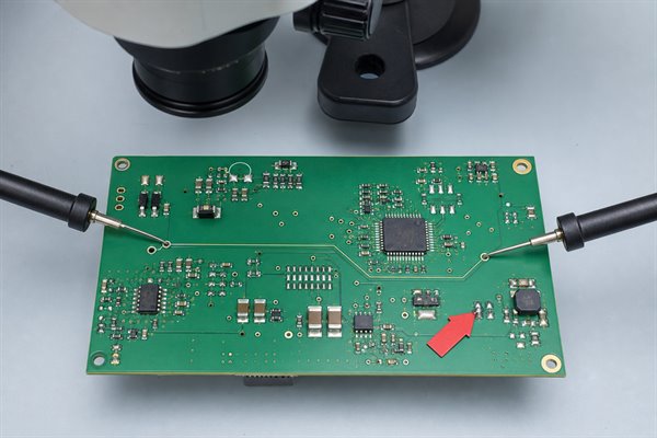
How Did Different Continuity Readings Confirm an Open PCB Trace in Practice?
A segmented continuity check can narrow an open net to the section between the last passing point and the first failing point. The sequence below is a controlled diagnostic example, not a customer case. The readings are illustrative; real limits depend on trace geometry, probe resistance, meter resolution, and the applicable acceptance criteria.
- Establish the baseline. With the probes shorted, assume the meter displays 0.3 Ω and produces a stable tone. This is the example lead-and-contact baseline.
- Test the full intended net. One probe touches the connector pad and the other touches the destination component pad. The example reading is OL with no tone, indicating that the complete route is not measurable.
- Divide the route. Move the second probe to an accessible test pad near the midpoint. A stable 0.4 Ω reading and tone show that the first segment is continuous within the example conditions.
- Test the remaining segment. Probe from the midpoint to the destination. OL repeats, narrowing the suspect region to that section rather than the connector or first trace segment.
- Inspect the localized area. Magnification may reveal a cracked trace, damaged via, incomplete pad connection, or solder-mask-covered defect. The physical finding should agree with the electrical boundary.
- Verify an approved repair. After authorized rework, retest the full net and adjacent nets. A stable low value on the intended net plus isolation from neighboring nets verifies those conditions at the meter’s test voltage, current, and resistance limits.
This divide-and-test method works wherever the net offers accessible pads, vias, connectors, or test points. It cannot pinpoint a hidden internal-layer break when there is no intermediate access. Depending on the structure and required evidence, the next step may be netlist-based testing, X-ray, microsectioning, or controlled destructive analysis.
FAQs About Symbol for Continuity on a Multimeter
Q1: Can continuity mode damage sensitive PCB components?
A1: It is usually low energy, but it is not risk-free. The meter applies a test voltage and current whose values vary by model. Sensitive semiconductor inputs, unpowered rails, and unknown circuits may respond unexpectedly. De-energize the assembly, observe ESD controls, and consult component and meter data when the test stimulus matters. If surrounding circuitry makes the result uncertain, isolate the device only through an approved rework procedure.
Q2: Why does the meter show low resistance without producing a beep?
A2: The reading may be above the meter’s audible threshold. The beeper may also be disabled, continuity mode may not be active, or the signal may not remain below the threshold long enough. Confirm the display icon, short the probes, and check the manual’s continuity specification. Use resistance mode when the numeric value matters more than an audible pass/fail response.
Q3: Can I test PCB continuity without removing components?
A3: Yes, but treat an in-circuit result as a first check. Components and parallel routes can create or block paths that would not exist on a bare PCB. Start with the schematic and expected net connections. If the measurement conflicts with the design, reverse polarity where relevant, try resistance or diode mode, and isolate a branch only when the procedure allows it.
Q4: Does probe polarity matter during a continuity test?
A4: Polarity normally does not matter for a simple copper trace. It can matter on an assembled PCB containing diodes, transistor junctions, protection devices, polarized capacitors, or active IC structures. Reverse the probes and compare both readings when semiconductor paths are possible. A directional difference is diagnostic evidence, not automatic proof of a fault.
Q5: Why does the continuity tone sound briefly and then stop?
A5: A capacitor may be charging from the meter’s test current. The initial current can appear as low resistance, followed by a rising reading and silence. Parallel circuits can create similar behavior. Remove power, discharge stored energy safely before testing, observe the direction and repeatability of the change, and compare it with the circuit diagram.
Q6: How can I check continuity with a multimeter without sound?
A6: Use the display in continuity or resistance mode. Short the probes first and note the lead baseline. Then compare the test-point value with the expected conductor resistance and the meter’s resolution. This works in a noisy shop or with a meter that has no buzzer, but the numeric reading still needs circuit context.
Q7: Can a continuity test prove that a solder joint is reliable?
A7: No, a static low-current test cannot prove long-term reliability. A cracked, poorly wetted, or mechanically weak joint may pass while stationary and fail under load, vibration, or thermal cycling. Combine electrical results with visual inspection and the applicable assembly acceptance criteria. Functional, load, thermal, or mechanical tests may be necessary when the failure risk demands them.
Q8: Which probes are best for fine-pitch PCB continuity testing?
A8: Fine insulated needle probes or suitable micro-hooks improve control. They reduce the exposed metal that can bridge neighboring pads. Stabilize the board, use magnification, and approach the test point at an angle that cannot slip into an adjacent conductor. Designed test pads are preferable to scraping solder mask or forcing a probe onto fragile component leads.
Q9: How do I distinguish normal ground continuity from a short?
A9: Confirm whether both points belong to the same intended ground net. Ground planes, shields, mounting holes, and connector grounds may legitimately show very low resistance. Use the schematic, netlist, and layout data instead of visual proximity. A short is an unintended connection between separate nets, so isolation testing between defined nets is more meaningful than testing “ground” without design context.
Q10: What production test provides stronger evidence than a manual beep?
A10: Netlist-based flying-probe or fixture testing provides traceable board-level evidence. Production electrical testing checks intended connections and isolation against defined data and limits. Agree the report format, coverage, test voltage, resistance limits, and controlling drawing before production. Functional testing may still be needed because a connected bare board is not the same as a working assembly.
For a PCB or PCBA manufacturing quotation, contact EBest Circuit at sales@bestpcbs.com. Send your Gerber or ODB++ files, BOM, quantity, stackup, assembly, programming, and test requirements so the requested scope can be reviewed before quotation.
You may also like








Tags: Continuity Beep Diagnosis, Continuity Test Mode, Multimeter Continuity Symbol, PCB Continuity Testing