





A remote control board is the electronic assembly that turns a user command into a wireless signal or converts a received signal into a physical action. Depending on the product, the board may transmit commands, receive and decode them, or combine both functions with motor, relay, lighting, audio, or power control.
Choosing the right board means matching the wireless link to the load, power source, enclosure, firmware, market requirements, and test plan. This guide follows that decision from system definition through manufacturing and sourcing.
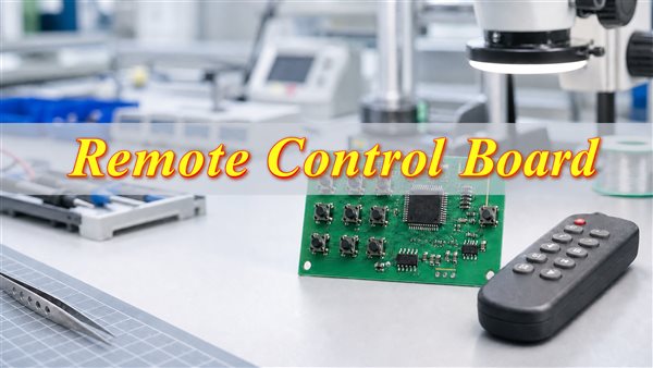
What Is a Remote Control Board?
A remote control board sends, receives, processes, or executes commands without a direct wired control connection. The term can describe the board inside a handheld remote, the receiver board inside the equipment, or an integrated control module containing wireless communication and output drivers.
A basic handheld board may contain buttons, a small microcontroller or encoder, an oscillator, a transmitter, and a battery supply. The equipment-side board usually contains a receiver, decoder or MCU, power regulation, protection components, and an output stage. That output stage may drive a relay, MOSFET, motor driver, buzzer, display, lamp, or another controller.
Because the phrase is broad, a useful specification should say whether the required product is a transmitter board, receiver board, relay board, motor-control board, or combined transmitter-and-receiver system.
How Does a Remote Control Board Work?
A remote control system converts an input into encoded data, sends it wirelessly, validates it at the receiver, and activates the intended output.
- Command input: A button, joystick, touch sensor, app, or host controller generates a command.
- Encoding: A microcontroller or dedicated encoder converts the command into a defined data frame.
- Transmission: An IR LED, RF stage, Bluetooth module, or Wi-Fi module sends the frame.
- Reception: The receiver detects the signal and passes valid data to its controller.
- Decision: Firmware checks the device address, command, timing, checksum, or pairing credentials.
- Output: A driver circuit operates the motor, relay, light, fan, sound system, or other load.
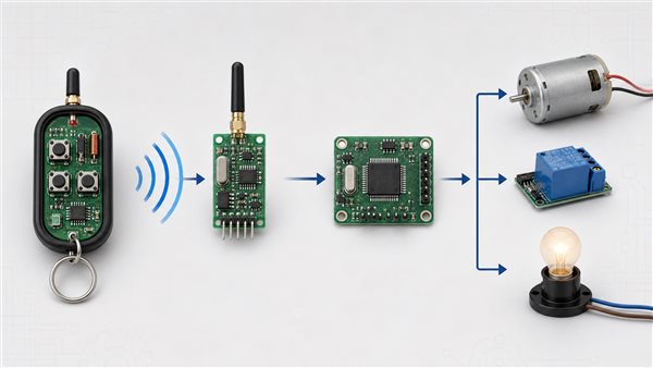
The exact signal chain depends on the product. A television remote may transmit short IR pulse sequences, while an RC vehicle may require a continuously updated, low-latency RF link. An industrial wireless switch may prioritize authentication, error checking, fail-safe behavior, and immunity to interference.
Transmitter Board vs Receiver Board vs Main Control Board
The transmitter creates commands, the receiver extracts them, and the main control board decides how the equipment responds. These functions may be placed on separate boards or integrated into one assembly.
| Board type | Primary function | Typical components | Common use |
| Transmitter board | Reads user input and sends commands | Buttons, MCU, encoder, oscillator, transmitter, antenna | Handsets, key fobs, RC controllers |
| Receiver board | Receives, validates, and forwards commands | Receiver IC, antenna, filter, MCU or decoder | Toys, gates, lighting, appliances |
| Main control board | Controls the equipment and its loads | MCU, power supply, drivers, protection, connectors | Fans, HVAC, motors, audio, automation |
Separating the boards can simplify service and allow one main controller to support different wireless options. Integration reduces connectors, enclosure volume, and assembly steps, but it can make RF layout, heat management, and repair more demanding.
What Components Are Used on a Remote Control Circuit Board?
The component set is determined by the communication method, processing load, output load, power source, and safety needs.
- Microcontroller or wireless SoC: Handles input scanning, data framing, pairing, security, timing, and output logic.
- Transmitter and receiver circuits: May be discrete devices, modules, or integrated into the MCU.
- Clock source: A crystal, resonator, or internal oscillator provides timing accuracy.
- Antenna and matching network: Transfer RF energy between the circuit and free space.
- IR devices: IR LEDs transmit optical commands, while receiver modules filter and demodulate them.
- Power regulation: LDOs, DC-DC converters, capacitors, and battery-protection devices stabilize the supply.
- Output drivers: MOSFETs, H-bridges, relays, triacs, and dedicated drivers control loads.
- Protection: ESD suppressors, reverse-polarity protection, flyback diodes, fuses, and current limiting reduce predictable damage.
- User interface: Tactile switches, membrane contacts, LEDs, displays, buzzers, and connectors support operation and service.
Review supply risk while selecting components. A wireless IC may work electrically yet remain unsuitable if its lifecycle, availability, firmware support, regulatory status, or alternate-source options do not fit the product.
What Types of Remote Control Boards Are Available?
Common designs use infrared, sub-GHz RF, 2.4 GHz RF, Bluetooth, Wi-Fi, or relay-control architectures.
| Type | Strength | Limitation | Typical application |
| Infrared remote control board | Low component cost and simple operation | Usually requires line of sight | TVs, audio equipment, air conditioners |
| Sub-GHz RF board | Good range and obstacle penetration | Regional frequency and interference constraints | Gates, relays, alarms, industrial switches |
| 2.4GHz proprietary RF board | Low latency and compact antenna options | Busy spectrum and tighter RF layout | RC cars, drones, toys, game controls |
| Bluetooth remote control board | Direct connection to phones and tablets | Pairing and software compatibility must be managed | Smart products, audio, lighting, portable devices |
| Wi-Fi remote control board | Network and internet connectivity | Higher power use and greater security responsibility | Smart home and connected equipment |
| Remote control relay board | Direct switching of isolated loads | Relay ratings and electrical clearances limit use | Lights, pumps, doors, sockets, machinery |
A universal remote control board may support several code sets or learn commands from existing handsets. “Universal” does not mean compatible with every protocol or appliance; verify the carrier frequency, modulation, command format, memory, and output interface.
IR vs Sub-GHz RF vs Bluetooth vs Wi-Fi: How Should You Choose?
Choose the wireless method by matching range, obstruction, power, latency, data, connectivity, security, and certification needs.
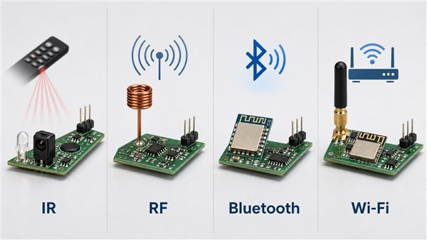
| Decision factor | IR | Sub-GHz RF | Bluetooth | Wi-Fi |
| Line of sight | Usually required | Not normally required | Not normally required | Not normally required |
| Battery demand | Low | Low to moderate | Low to moderate | Moderate to high |
| Phone control | Limited | Requires an interface | Native on many devices | Native through network software |
| Remote internet access | No | Not by itself | Usually through a gateway | Yes, with secure system design |
| Best fit | Simple room controls | Longer-range direct control | Local smart control | Connected products |
For RF products, involve PCB layout and enclosure teams early. Ground geometry, nearby parts, cables, metal, and the enclosure can detune the antenna. Even a proven radio module must be tested in the assembled product.
Remote Control Board Frequencies and Channel Counts
Frequency identifies the radio band, while channel count describes how many independent functions the system can command. Neither term alone defines compatibility.
Legacy and low-cost RC systems may use 27MHz or 40MHz. Wireless switches and relay boards often use sub-GHz bands such as 315MHz or 433MHz, subject to destination-market rules. Modern RC, Bluetooth, and Wi-Fi products frequently operate around 2.4GHz.
The permitted frequency, power, duty cycle, bandwidth, and test requirements depend on the market and application. Verify them before final hardware release.
A two-channel relay board can independently switch two outputs. An RC car described as four-channel may map its channels to forward, reverse, left, and right, but terminology varies between vendors. Specify the required commands, simultaneous operations, update rate, latency, and fail-safe state instead of relying only on the advertised channel number.
Where Are Remote Control Boards Used?
Remote control boards support equipment that must be operated without a direct wired interface.
- RC vehicles and toys: Motor direction, steering, lights, sound, and accessory control.
- Drones and robots: Low-latency commands, telemetry, safety states, and multi-axis control.
- Fans and HVAC: Speed, temperature, mode, timer, louver, and power control.
- TV and audio: Input, menu, playback, sound, and remote volume control.
- Lighting and power: Lamps, sockets, dimming circuits, and multi-channel relay outputs.
- Doors and shutters: Motor direction, limit switches, photocells, safety inputs, and access control.
- Industrial equipment: Start, stop, jog, positioning, alarms, and safe shutdown.
- Smart products: Bluetooth or Wi-Fi control through a phone, hub, or cloud-connected service.
The application sets the risk level. A toy light controller and a machine-motion controller should not share the same assumptions about interference, unintended activation, watchdogs, emergency stops, enclosure protection, or validation evidence.
Remote Control PCB Design Considerations
A reliable design treats the antenna, power supply, processor, output loads, firmware, and enclosure as one system.
- Define performance: Set range, latency, packet-loss tolerance, and fail-safe behavior before choosing the radio.
- Protect the antenna zone: Keep antennas away from ground copper, noisy converters, motors, relays, cables, and metal enclosure parts.
- Separate noisy circuits: Isolate sensitive receiver paths from high-current switching loops and fast digital edges.
- Stabilize the supply: Provide local decoupling and enough bulk capacitance for transmitter bursts, relay coils, or motor start current.
- Add circuit protection: Use suitable flyback, surge, reverse-polarity, overcurrent, and ESD protection.
- Control hazardous voltage: Check creepage and clearance where a remote control switch board handles hazardous voltage.
- Plan test access: Provide programming, debug, and production-test points without creating antenna or ESD problems.
- Calculate battery life: Use real duty cycles, sleep current, retransmissions, indicator LEDs, and regulator losses.
Many compact consumer designs can use conventional FR4 PCB construction. Products with controlled RF transmission paths, higher data rates, or demanding loss budgets may require closer laminate and impedance review; the need for a dedicated RF PCB solution should be based on the actual frequency, topology, insertion loss, antenna, and performance target.
How Is a Remote Control Board Manufactured and Tested?
Manufacturing combines PCB fabrication, assembly, firmware programming, inspection, functional testing, and radio verification.
- Engineering review: Check Gerber or ODB++, stackup, BOM, assembly data, test points, antenna constraints, and panelization.
- PCB fabrication: Produce the copper pattern, plated holes, solder mask, surface finish, routing, and electrical test according to the approved build data.
- Assembly: Print solder paste, place SMT components, reflow, install through-hole parts, and complete required cleaning or selective soldering.
- Inspection: Use visual inspection and AOI; apply X-ray when hidden solder joints or package risks justify it.
- Programming: Load controlled firmware and configuration data with revision traceability.
- Functional test: Verify input scanning, pairing, commands, outputs, indicators, standby current, and fault states.
- Wireless test: Check communication, sensitivity, output behavior, range, interference response, and antenna consistency using a defined fixture and test environment.
For production, a visual “works once” check is insufficient. Define pass limits, RF conditions, supply extremes, loads, firmware revision, pairing procedure, and failure handling.
When sourcing PCB Assembly (PCBA), include the programming and functional-test requirements in the quotation package rather than adding them after pilot production.
Common Remote Control Board Problems and Troubleshooting
Most failures can be narrowed to power, input contacts, communication, firmware, pairing, antenna, output drivers, or environmental damage.
| Symptom | Likely area | First checks |
| No response | Battery, regulator, reset, oscillator, firmware | Confirm supply voltage, current draw, reset state, and clock activity |
| Short communication range | Antenna, battery, RF matching, enclosure | Compare with a known-good unit and test outside the enclosure |
| Some buttons fail | Keypad contacts, membrane, traces, scan firmware | Inspect contamination, wear, corrosion, and matrix continuity |
| Pairing fails | Protocol, stored credentials, timing, incompatible hardware | Verify firmware versions, pairing sequence, and receiver state |
| Relay clicks but load stays off | Contacts, connector, fuse, load wiring | Measure contact continuity and inspect the load path safely |
| Motor moves one direction only | H-bridge, MOSFET, gate drive, command decoding | Compare both control signals and inspect the output stage |
Disconnect hazardous voltages before inspection. Battery leakage should be addressed quickly because alkaline residue can damage pads, vias, switches, and fine copper traces. Cleaning may restore surface contamination, but lifted pads, corroded vias, damaged ICs, or carbonized insulation normally require component-level repair or board replacement.
What Affects Remote Control Board Price?
Remote control board price is driven by hardware, PCB construction, firmware, testing, compliance work, quantity, and accessories.
- Wireless architecture: Protocol, radio chipset, antenna, and module versus chip-down implementation
- PCB construction: Board dimensions, layer count, laminate, copper weight, finish, and impedance requirements
- Electronic content: MCU, display, sensors, relays, connectors, motor drivers, and power components
- Software scope: Firmware development, mobile-app integration, security, and update requirements
- Production testing: Programming fixtures, functional-test fixtures, radio tests, and traceability
- Mechanical package: Enclosure, keypad, membrane, labels, cables, batteries, and paired receiver or transmitter
- Production volume: Prototype quantity, pilot build, forecast, component lifecycle, and alternate sourcing
- Market requirements: Destination-market compliance and any application-specific validation
A useful quotation separates engineering and tooling charges from recurring unit cost. It should state what firmware, testing, packaging, accessories, and components are included. A low board-only price can be misleading when programming, pairing, fixtures, cables, or the matched remote are excluded.
How to Choose a Remote Control Board and Evaluate a Supplier
Define the control problem first, then evaluate boards and suppliers against engineering, testing, documentation, and lifecycle needs.
- Controlled equipment: What equipment and loads will the board control?
- Link performance: What range, latency, update rate, and fail-safe behavior are required?
- Wireless method: Which protocol and destination-market frequency rules apply?
- Channel count: How many commands or channels are needed, including future expansion?
- Power budget: What are the input voltage, peak current, standby current, and battery-life targets?
- Mechanical limits: What are the board outline, enclosure, antenna, connector, and mounting limits?
- Firmware ownership: Who owns the source code, programming files, and security credentials?
- Quality evidence: Which inspections, functional tests, wireless tests, and records are required?
- Volume plan: What are the prototype, pilot, and forecast production quantities?
- Change control: How will substitutions, firmware changes, and end-of-life risks be controlled?
Ask the supplier to identify manufacturing, RF, component, and test risks before quotation. Confirm how it controls BOM revisions, firmware programming, functional testing, and engineering changes. EBest Circuit supports prototype, sample-development, volume-production, and custom-engineering discussions; confirm project-specific requirements during quotation.
Frequently Asked Questions
These supplemental questions address coding, pairing, security, production records, coating, relay contacts, and lifecycle planning.
Q1: What is the difference between fixed-code and rolling-code remote control systems?
A1: A fixed-code system repeats the same identifier, while a rolling-code system changes the accepted code after each valid command. Rolling codes can reduce replay risk, but transmitter and receiver synchronization must be designed and tested carefully.
Q2: Can several remotes be paired with one receiver board?
A2: Yes, if the receiver firmware and memory support multiple authorized transmitters. The product specification should define the maximum number of remotes, enrollment procedure, deletion method, and behavior when memory is full.
Q3: Can one remote control several receiver boards?
A3: It can when the protocol supports group addressing, broadcast commands, or selectable device addresses. Designers should prevent unintended simultaneous operation and provide a clear method for assigning or changing groups.
Q4: What should happen when a paired remote is lost?
A4: The receiver should provide a controlled way to revoke the missing remote and enroll a replacement. Security-sensitive products may also need an audit record, credential reset, or full re-pairing procedure.
Q5: Should wireless firmware support field updates?
A5: Field updates are useful when security fixes, protocol changes, or product improvements are expected. The update path should authenticate firmware, survive interrupted power, protect rollback behavior, and preserve pairing data when required.
Q6: Can conformal coating change wireless performance?
A6: Yes, coating material and thickness can detune antennas or add loss around RF structures. Keep-out rules should be defined on the assembly drawing, and coated production-intent units should be included in wireless validation.
Q7: What pairing data should be recorded during production?
A7: Record the product serial number, firmware revision, paired-device identifier, test result, and rework status when traceability is required. Avoid storing secret keys in exposed production reports.
Q8: What do normally open and normally closed relay contacts mean?
A8: Normally open contacts are disconnected when the relay is idle; normally closed contacts are connected when it is idle. The selected state should support the required power-off and fault behavior.
Q9: How should unused remote control channels be handled?
A9: Unused commands should be ignored safely and documented rather than left with undefined behavior. Firmware should prevent them from activating test modes, reserved outputs, or future functions unintentionally.
Q10: When should a radio module be preferred over a chip-down RF design?
A10: A module can reduce RF layout effort and speed development when its size, cost, interfaces, availability, and approvals fit the product. A chip-down design may offer more integration and cost control at volume but requires deeper RF engineering and validation.
Plan the board around the complete control system.
Specify the complete remote control board system before ordering: commands, wireless link, loads, power, enclosure, firmware, fail-safe behavior, tests, and destination market. This exposes integration risks before pilot production.
For a manufacturing review and quotation, send your Gerber or ODB++, NC drill files, BOM, quantities, stackup, assembly requirements, firmware or programming files, paired-device details, communication range, functional-test requirements, and required quality documentation to sales@bestpcbs.com.
You may also like



Tags: remote control board, remote control circuit board, remote control PCB, wireless control board