

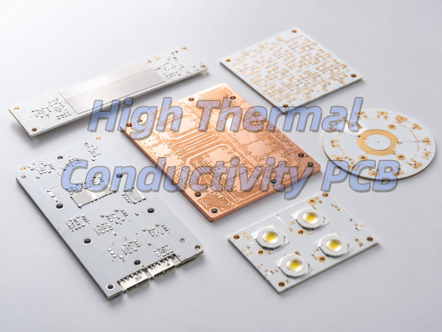
What Is a High Thermal Conductivity PCB?
High thermal conductivity PCBs are special circuit boards that move heat away from electronic parts quickly. Regular FR-4 boards only conduct 0.3-0.5 W/m·K of heat, but these boards use metal or ceramic cores to do 2-100 times better. They work as both a circuit board and a heat spreader, so you often don’t need big separate heatsinks.
Aluminum PCBs are the most popular type, making up over 85% of the market. They are cheap and work well for most power products. Other types include copper core, IMS, and ceramic PCBs for more demanding uses.
Why Is High Thermal Conductivity Important in PCB Design?
Good heat conduction makes electronics last longer and work better. A 10°C drop in component temperature can double the life of semiconductors. Bad heat dissipation makes LEDs lose 70% of their brightness in 3 years and causes power parts to fail suddenly.
In cars, thermal stability keeps safety systems working from -40°C to 125°C. Without high thermal conductivity PCBs, modern small, high-power devices like EV chargers and 5G phones would overheat and break.
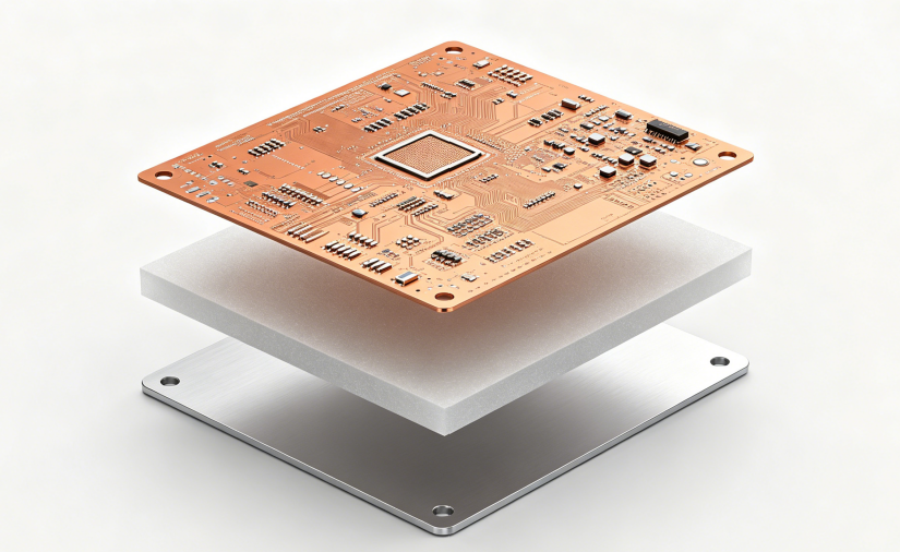
What Materials Are Used in High Thermal Conductivity PCBs?
High thermal conductivity PCBs use three main layers: a copper circuit layer, a thermally conductive dielectric layer, and a core base. The dielectric layer is the most important because it causes 70-90% of the total heat resistance
Core Material Performance Comparison
| Material Type | Thermal Conductivity (W/m·K) | Max Temperature (°C) | Cost Index | Best For |
|---|---|---|---|---|
| Aluminum 6061 | 150-205 | 130 | 1.0 | General power products |
| Pure Copper | 385-400 | 150 | 3.5 | High-current modules |
| Alumina Ceramic | 18-36 | 1000+ | 2.5 | Sensors and industrial parts |
| Aluminum Nitride | 150-230 | 1000+ | 8.0 | Medical and aerospace |
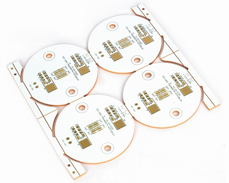
Aluminum PCB, Copper Core PCB, IMS PCB, and Ceramic PCB: What Is the Difference?
Each type has its own strengths for different jobs. Aluminum PCBs are the cheapest and most common. Copper core PCBs conduct heat better for high-power uses. IMS PCBs have better insulation, and ceramic PCBs work in extreme temperatures.
PCB Type Comparison
| PCB Type | Overall Heat Conductivity (W/m·K) | Insulation Voltage | Cost | Best Use |
|---|---|---|---|---|
| Aluminum PCB | 1-5 | 1-3 kV | Low | LED lights, small power supplies |
| Copper Core PCB | 3-10 | 1-3 kV | Medium | Motor controls, EV chargers |
| IMS PCB | 1-9 | Up to 5 kV | Medium | Power converters, car electronics |
| Ceramic PCB | 18-230 | >15 kV/mm | High | RF devices, medical lasers |
How to Choose the Right Thermal Conductivity Rating?
The right rating depends on how much power your device uses. Too low and it overheats; too high and you waste money. A simple rule: add 0.5 W/m·K for every extra 10W of power.
For small LED bulbs under 50W, 1.0-1.5 W/m·K works fine. For street lights (50-150W), use 2.0-3.0 W/m·K. For industrial converters over 300W, you need 5.0+ W/m·K or a copper core PCB.
Thermal Conductivity vs Thermal Resistance: What Should Designers Know?
Thermal conductivity is how well a material moves heat. Thermal resistance is how hard it is for heat to pass through a whole structure. Many people mix these up, which leads to bad designs.
The formula is simple: Thermal Resistance = Thickness ÷ (Conductivity × Area). This means a thin, high-conductivity layer with a big area works best. For example, a 100μm thick 3 W/m·K dielectric is the same as a 200μm thick 6 W/m·K one.
How Does Copper Thickness Affect Thermal Performance?
Thicker copper carries more current and spreads heat better. It reduces resistive heating and moves heat away from hot parts faster. Increasing copper from 1 oz to 2 oz can lower component temperature by 5-10°C.
Copper Thickness Guide
| Copper Weight | Thickness (μm) | Current per 1mm Width | Typical Use |
|---|---|---|---|
| 1 oz | 35 | 3-5 A | General circuits |
| 2 oz | 70 | 6-10 A | Power supplies, LED drivers |
| 3 oz | 105 | 10-15 A | High-current boards |
| 4 oz+ | 140+ | 15-25 A+ | Heavy power modules |
How to Improve Heat Dissipation in PCB Layout?
Layout choices often matter more than material selection. Even the best material won’t work if heat can’t flow to the cooling system. Follow these simple rules for better results.
First, put high-power parts near the board edges or mounting holes. Use big copper pads under hot components and add copper pours around them. Use thermal vias (0.3mm diameter, 1mm apart) under exposed pads. Also, keep heat-sensitive parts at least 10mm away from hot areas.
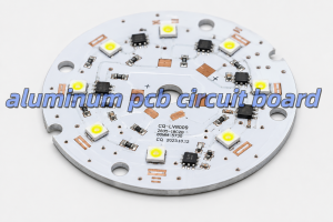
What Applications Use High Thermal Conductivity PCBs?
High thermal conductivity PCBs are used everywhere heat is a problem. The biggest use is LED lighting, where they make bulbs last 3-5 times longer. They are also common in car electronics, power supplies, and 5G communication devices.
Other uses include motor controls, medical equipment, and aerospace parts. Any device that is small but uses a lot of power will benefit from a high thermal conductivity PCB.
How to Choose a Reliable High Thermal Conductivity PCB Manufacturer?
A good manufacturer has experience with all types of high thermal conductivity PCBs and can help with design. Look for one that uses high-quality materials and has strict quality control.
Key things to check: experience with aluminum, copper, and ceramic PCBs; ability to do thermal analysis; stable material supply; and compliance with IPC, RoHS, and REACH standards. Also, make sure they can support both prototypes and mass production.
Why Choose EBest Circuit for High Thermal Conductivity PCB Projects?
EBest Circuit offers complete high thermal conductivity PCB services, from design review to mass production. We have over 10 years of experience with all types of thermal PCBs and work with top material suppliers.
Our team can help you optimize your stackup, select the right materials, and fix thermal issues before production. We support fast prototypes and reliable mass production, so you can get your products to market quickly.
FAQs About High Thermal Conductivity PCB
Q1: Can high thermal conductivity PCBs be multilayer?
A1: Yes, but they are more expensive than single-layer ones. Most designs use 1-2 layers, with 4+ layers only for special high-density needs.
Q2: How much more do they cost than FR-4?
A2: They usually cost 2-3 times more than FR-4. But they often eliminate the need for separate heatsinks, saving total system cost.
Q3: What is the maximum voltage they can handle?
A3: Standard aluminum PCBs handle 1-3kV. Special high-voltage designs can go up to 5kV, and ceramic PCBs offer even higher insulation.
Q4: Can aluminum PCBs be bent?
A4: Yes, 5052 aluminum alloy bends well. This is useful for curved LED lights and other custom shapes.
Q5: How do I test the actual thermal conductivity?
A5: Ask your manufacturer for laser flash analysis (LFA) test data. Datasheet values are often higher than real-world performance.
You may also like


Tags: aluminium pcb thermal conductivity, aluminum pcb, ceramic PCB, high thermal conductivity materials, thermal conductivity