

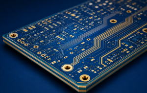
Rogers 5880 is a premium PTFE-based high frequency laminate developed for low-loss RF and microwave circuits. If you are building antennas, power dividers, couplers, radar boards, or broadband RF structures, RT5880 is one of the most trusted materials on the market because it combines a very low dielectric constant, very low loss, low moisture absorption, and stable electrical behavior over a wide frequency range.
At EBest, we manufacture rogers 5880 pcb solutions for customers who need dependable RF performance, controlled impedance, and production support from prototype to volume. Whether you are searching for the rogers 5880 datasheet, comparing rogers 5880 thickness options, or checking the rogers 5880 dielectric constant for your next layout.
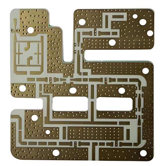
Rogers 5880 PCB Material
Why Choose Rogers 5880 PCB for RF Design?
When frequency increases, the limitations of standard materials become very clear. Signal attenuation rises quickly, impedance becomes harder to control, and performance starts to drift with temperature and environment.
Rogers 5880 solves these issues from the material level:
- Ultra-low loss (Df ~0.0009)
Helps maintain signal strength over long RF transmission paths
- Low dielectric constant (Dk 2.20)
Enables stable impedance and easier transmission line design
- Uniform dielectric structure
Eliminates fiber weave effect and improves signal consistency
- Low moisture absorption (0.02%)
Keeps performance stable in humid or outdoor environments
- High-frequency capability
Suitable for applications above 10 GHz and even millimeter-wave
Compared with FR4, this is not a small improvement. It is a shift from “usable” to “reliable” in RF design.
What Is Rogers 5880 Material?
Rogers 5880, also called rogers duroid 5880 or RT5880, is part of the RT/duroid laminate family. It is a high frequency substrate made from PTFE reinforced with randomly oriented glass microfibers. That reinforcement helps maintain dielectric constant uniformity from panel to panel and across frequency, which is one reason this material is widely used in precision RF designs.
This material is especially suitable for:
- RF antennas
- microwave circuits
- microstrip and stripline designs
- point-to-point digital radio antennas
- millimeter-wave structures
- military radar related circuitry
- commercial airline broadband antenna systems
Rogers 5880 Datasheet Overview
| Parameter | Value | Test Condition / Notes |
| Dielectric Constant (Dk) | 2.20 ± 0.02 | Process value, @10 GHz |
| Design Dielectric Constant | 2.20 | Typical design value |
| Dissipation Factor (Df) | 0.0009 | @10 GHz |
| Dissipation Factor | 0.0004 | @1 MHz |
| Thermal Coefficient of Dielectric Constant | -125 ppm/°C | Typical |
| Volume Resistivity | 2 × 10⁷ MΩ·cm | Typical |
| Surface Resistivity | 3 × 10⁷ MΩ | Typical |
| Moisture Absorption | 0.02% | Very low moisture uptake |
| Specific Heat | 0.96 J/g/K | Typical |
| Density | 2.2 g/cm³ | Nominal |
| Thermal Conductivity | 0.20 W/m/K | Typical |
| Coefficient of Thermal Expansion, X-axis | 31 ppm/°C | Typical |
| Coefficient of Thermal Expansion, Y-axis | 48 ppm/°C | Typical |
| Coefficient of Thermal Expansion, Z-axis | 237 ppm/°C | Typical |
| Tensile Modulus | 1070 MPa | Machine direction |
| Tensile Modulus | 860 MPa | Cross direction |
| Dimensional Stability | < 0.5 mm/m | After etch + E2/150°C |
| Peel Strength | 8.5 pli (1.5 N/mm) | 1 oz ED copper, after solder float |
| Flammability | V-0 | UL 94 |
| Operating Temperature | Up to high-temperature RF use | Commonly used in demanding RF/microwave environments |
Rogers 5880 Thickness & Stack-Up Options
rogers 5880 thickness is not just a mechanical choice. It directly affects impedance, signal confinement, and manufacturability.
Common thickness options:
- 5 mil (0.127 mm)
- 10 mil (0.254 mm)
- 20 mil (0.508 mm)
- 31 mil (0.787 mm)
- 62 mil (1.575 mm)
Typical design approach:
- Thin cores → RF signal layers
- Thicker cores → structural support
- Hybrid stack-up → Rogers + FR4 for cost optimization
In real projects, engineers rarely use Rogers 5880 across the entire board. Instead, it is applied strategically where RF performance matters most.
Typical Applications of RT5880
RT5880 is used in products where the electrical performance of the PCB material directly affects signal quality, range, or accuracy. These are usually applications operating at high frequency, high data integrity requirements, or both.
Common applications include:
- RF antennas
Used in antenna boards where dielectric stability affects resonance, matching, and radiation efficiency.
- 5G communication equipment
Suitable for high frequency transmission paths where FR4 loss becomes too high.
- Satellite communication systems
Chosen for low loss and dependable signal behavior across demanding environments.
- Automotive radar
Often used in radar modules where stable dielectric properties support accurate detection.
- Aerospace and defense electronics
Applied in systems that require both electrical consistency and long-term reliability.
- Microwave circuits
Used in couplers, filters, amplifiers, and other circuits where signal loss must stay low.
This is why RT5880 appears so often in advanced RF products. Once the circuit becomes sensitive to loss, dielectric variation, or transmission precision, this material moves from optional to highly practical.
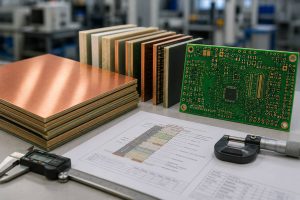
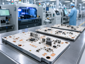
Rogers 5880 PCB Manufacturing at EBest Circuit
Even the best laminate cannot compensate for poor manufacturing control. In RF PCB production, the final performance depends not only on the material itself, but also on drilling accuracy, etching control, lamination quality, and impedance management.
At EBest Circuit, we support rogers 5880 pcb manufacturing for both prototypes and volume production. We also help customers evaluate whether a full Rogers build or a hybrid Rogers + FR4 structure makes more sense for the project.
Our manufacturing capability includes:
- 1–32 layer PCB fabrication
- Rogers + FR4 hybrid stack-up support
- Controlled impedance production
- Fine trace processing
- RF-oriented DFM review
- Prototype and mass production support
What customers usually need from us:
- Material selection suggestions
- Stack-up optimization
- Cost-performance balancing
- Better manufacturability for RF structures
- Faster transition from design to production
For high frequency boards, engineering support before fabrication often matters as much as the fabrication itself.
Get a Fast Quote for Rogers 5880 PCB
If your project involves RF, antenna, microwave, or other high frequency circuits, choosing the right laminate is only part of the solution. The other part is working with a manufacturer that understands how material choice, stack-up, and process control affect real electrical results.
To get a quotation faster, you can send:
- Gerber files
- Stack-up requirements
- Impedance targets
- Board thickness request
- BOM list if PCBA is needed
What you can expect from us:
- Fast quotation response
- DFM feedback
- Stack-up suggestions
- Cost-performance optimization
- Support from prototype to production
📩 Email: sales@bestpcbs.com
📞 Phone: +86-755-2909-1601
EBest Circuit – One-stop PCB and PCBA solution for high frequency and RF projects.
FAQs About Rogers 5880 PCB
1. What is Rogers 5880 used for?
Rogers 5880 is mainly used in RF and microwave PCB applications where low signal loss and stable dielectric properties are important. Typical examples include antennas, radar modules, satellite communication boards, and other circuits operating at high frequency.
2. Is Rogers 5880 better than FR4?
It is better for high frequency applications, but not in every situation. FR4 remains a good choice for many low-frequency and cost-sensitive designs, while Rogers 5880 is chosen when signal loss, dielectric stability, and impedance precision become more important than raw material cost.
3. Can Rogers 5880 be used in multilayer PCB?
Yes, and it often is. In many practical projects, Rogers 5880 is used as part of a hybrid multilayer stack-up together with FR4. This allows designers to place the premium RF material only where it adds real value, while keeping the overall board structure more economical.
4. What thickness options are available for Rogers 5880?
Common options include 5 mil, 10 mil, 20 mil, 31 mil, and 62 mil, though availability can vary by project needs. Thickness is usually selected based on impedance targets, transmission line geometry, and mechanical requirements rather than personal preference.
You may also like
Tags: rogers 5880, rogers 5880 datasheet, rogers 5880 dielectric constant, rogers 5880 pcb, rogers 5880 thickness, rogers duroid 5880, RT5880