

A PCB socket is a critical electromechanical component that provides a removable interface between a printed circuit board (PCB) and another device, such as an integrated circuit (IC), module, or cable. This guide will comprehensively explore the types, functions, selection criteria, and correct installation methods for reliable PCB sockets to ensure your electronic assemblies are both robust and serviceable.
Do you struggle with selecting the right PCB socket connector for your project? Many engineers and procurement specialists face common challenges that can lead to project delays, increased costs, and field failures. The key difficulties often include:
- Unreliable Connections: Choosing the wrong type can result in intermittent signals or complete failure.
- Mechanical Fit Issues: Sockets that don’t mate correctly can cause misalignment and damage.
- Incorrect Orientation: Improper installation of polarized sockets leads to reverse-polarity and short circuits.
- Complex Installation: Some sockets, like collet socket types, require specific pressing tools and techniques.
- Difficulty in Verification: After soldering, it’s challenging to check if the socket is properly seated and functional.
Fortunately, these challenges can be overcome through careful selection and proper handling.
- Prioritize Quality Materials: Select sockets with high-quality phosphor bronze or beryllium copper contacts for superior conductivity and spring tension.
- Verify Mechanical Specifications: Meticulously check datasheets for footprint dimensions, pin spacing, and mating height before procurement.
- Understand Polarization Keying: Always identify the polarization mark (beveled edge, dot, pin-1 indicator) on the socket and PCB silkscreen.
- Use Appropriate Tooling: Employ dedicated press fit tools or alignment jigs for installing pcb pin sockets to avoid damage.
- Implement Electrical Testing: Use continuity testers and custom test fixtures to verify each pin after assembly.
At BEST Technology, we are a leading manufacturer specializing in high-quality PCB fabrication and PCBA assembly services. While we are not a connector manufacturer, our expertise lies in providing a robust foundation for all your electronic components, including various PCB sockets. We ensure that the boards we produce meet the precise specifications and stringent quality standards required for reliable socket mounting and soldering. By offering a complete solution from board fabrication to component assembly, we help our clients achieve optimal performance and reliability in their final products. For inquiries, pls feel free to contact us at sales@bestpcbs.com.
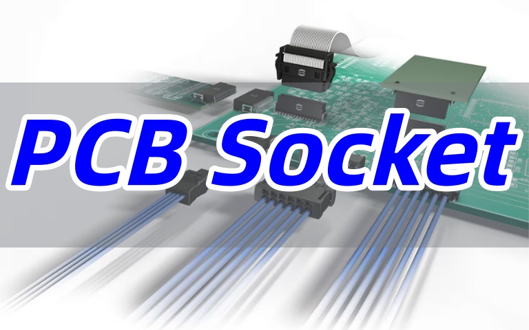
What is a PCB Socket?
A PCB socket, also known as a PC board connector or PC board sockets, is a device mounted on a circuit board that allows for the plugging and unplugging of components without soldering them directly. This facilitates easier testing, upgrades, and repairs. Essentially, it acts as an intermediary, providing both an electrical path and mechanical support.
These sockets come in various forms, from simple pin sockets for PCB used for microcontrollers to complex PCB edge connector sockets for expansion cards. The primary advantage is serviceability; for instance, a costly processor can be easily replaced if it fails, without subjecting the main PCB to heat stress from desoldering.
In summary, a socket PCB is a fundamental component for creating modular and maintainable electronic designs.
What are the Different Types of PCB Sockets?
The world of PCB socket types is diverse, catering to different applications, signals, and power requirements. Understanding these types is the first step in choosing a reliable option.
- IC and Chip Sockets: These include standard PCB pin sockets (or headers) and PCB transistor sockets.
They are designed for integrated circuits and discrete components, often arranged in strips (PCB socket strip) or dual-in-line (DIP) packages.
PCB hot swap sockets are a popular subtype for mechanical keyboards.
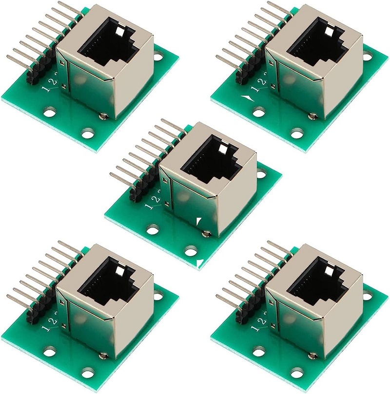
- I/O Connector Sockets: This category includes sockets for external interfaces, such as USB PCB socket (including USB C PCB socket, micro USB PCB socket), rj45 PCB socket, HDMI PCB socket, and RCA PCB socket.
They are typically PCB mount types.
- Power Connector Sockets: Sockets like the 2mm banana socket PCB mount and PCB mount banana socket are used for test points and power input.
PCB power sockets and PCB relay sockets (including automotive relay PCB socket) also fall into this group.
- Audio/Video Sockets: Examples are the 3.5 mm PCB mount stereo socket and PCB mount RCA socket (phono socket PCB mount).
- Specialty Sockets: This includes PCB tube sockets (like a 9 pin tube socket PCB), mill connector styles, and castellated PCB socket for module-to-board attachment.
In conclusion, selecting the correct type—whether it’s a PCB header socket for internal connections or a USB socket PCB mount for external ports—is crucial for the functionality and reliability of the end product.
What does Socket Mean on a Motherboard?
On a motherboard, a “socket” specifically refers to a PCB mount socket designed to house the central processing unit (CPU). It is one of the most critical PCB connectors on the board. This socket provides the physical and electrical interface between the motherboard’s circuitry and the CPU.
These sockets are highly specialized. They have a specific pin count (e.g., LGA 1700, AM5) and a sophisticated locking mechanism to secure the CPU. The contacts inside the socket must maintain perfect electrical continuity under thermal cycling and mechanical stress. The design of the socket, including the type (LGA, PGA), determines CPU compatibility.
Therefore, the motherboard socket is a key factor in a system’s upgrade path and performance.
Is LGA 1851 Dead?
The question of whether a socket is “dead” refers to if it has been abandoned by the manufacturer for future CPU generations. As of now, Intel’s LGA 1851 socket is a new platform, not a dead one. It was introduced with Intel’s Arrow Lake processors and is expected to be supported for future generations, following Intel’s typical tick-tock cycle.
When evaluating a socket like LGA 1851 for a new design, it’s a strategic decision. Choosing a new socket often ensures longer-term CPU availability and upgrade options. However, for a project with a fixed, long-life requirement, a more mature, stable socket might sometimes be a better choice to avoid future platform changes.
Pls always consult the latest roadmaps from CPU manufacturers for the most current information.
Does the Direction of Sockets Matter PCB?
Absolutely, the direction of sockets matters critically on a PCB. Incorrect orientation can lead to catastrophic failures, including reverse polarity, short circuits, and mechanical incompatibility. Here’s a breakdown for common sockets:
- RJ45 PCB Socket: These sockets have a specific orientation.
The locking tab must face the correct direction to allow an Ethernet cable to snap in and out properly.
Furthermore, the pin-1 assignment for the twisted pairs must align with the PCB layout according to T568A or T568B wiring standards. - USB PCB Socket: All USB PCB sockets (A, B, C, Micro, Mini) are polarized.
The USB socket PCB mount has a blocked plastic section inside that prevents a cable from being inserted upside down.
The PCB footprint is asymmetrical to enforce correct placement during assembly. - 3.5 mm PCB Mount Stereo Socket: This audio jack is typically polarized by the arrangement of its solder lugs (Tip, Ring, Sleeve).
The footprint on the PCB is not symmetrical, preventing a 180-degree rotation that would swap the audio channels. - Relay PCB Socket: PCB mount relay sockets have a keyed shape that matches the relay’s base.
Plugging a relay in the wrong way is physically impossible if the socket is correctly oriented on the PCB.
The coil and contact assignments are fixed by this orientation. - RCA Socket PCB Mount: While a single RCA plug can be rotated, the PCB mount RCA sockets are often designed with a grounding tab or a specific shape for mechanical stability.
On the PCB, they must be placed so the signal pin connects correctly.
Mistakes in orientation can render a board unusable. A reversed USB socket PCB can short the 5V power rail to the data lines, potentially damaging both the host and the peripheral. Therefore, always double-check the manufacturer’s datasheet and the PCB’s silkscreen for polarization marks.
What are the Functions of 2mm Banana Socket PCB Mount?
The primary function of a 2mm banana socket PCB mount is to provide a safe and convenient test point or power connection point on a circuit board. Its specific functions include:
- Test and Measurement: It allows engineers to easily connect multimeter probes, oscilloscope leads, or other test equipment without needing to touch sensitive solder points directly.
- Power Input/Output: These sockets can serve as a durable connection for supplying power to a board or for routing power to another module.
- Modular Connections: They enable quick-connect/disconnect capabilities for internal wiring within a system, such as connecting a front panel display to a main board.
- High Current Handling: Compared to standard pin headers, banana socket PCB types are designed to handle higher currents, making them suitable for power supplies and amplifiers.
In essence, the PCB banana socket offers a robust, reusable interface that simplifies debugging, testing, and configuration.
How do a 3-Pin PCB Mount Socket Work?
A 3-pin PCB mount socket works by providing three distinct electrical contacts housed within an insulating body. A common example is a socket for a 3-pin sensor or a transistor.
- Physical Interface: The socket is soldered onto the PCB, with its three pins (or solder lugs) connecting to three separate traces on the board.
- Component Insertion: The component with three matching pins is inserted into the socket’s receptacles. The receptacles, often made of springy metal (spring leaf socket PCB terminals), grip the component’s pins firmly to ensure a reliable electrical connection.
- Electrical Pathway: Each pin of the component makes contact with a corresponding metal receptacle inside the socket, which is connected to the PCB. This completes the circuit between the component and the board.
- Removability: The component can be easily removed for replacement or upgrade without any soldering, protecting the PCB from heat damage.
This mechanism is fundamental to many circuit board sockets, providing flexibility and serviceability.
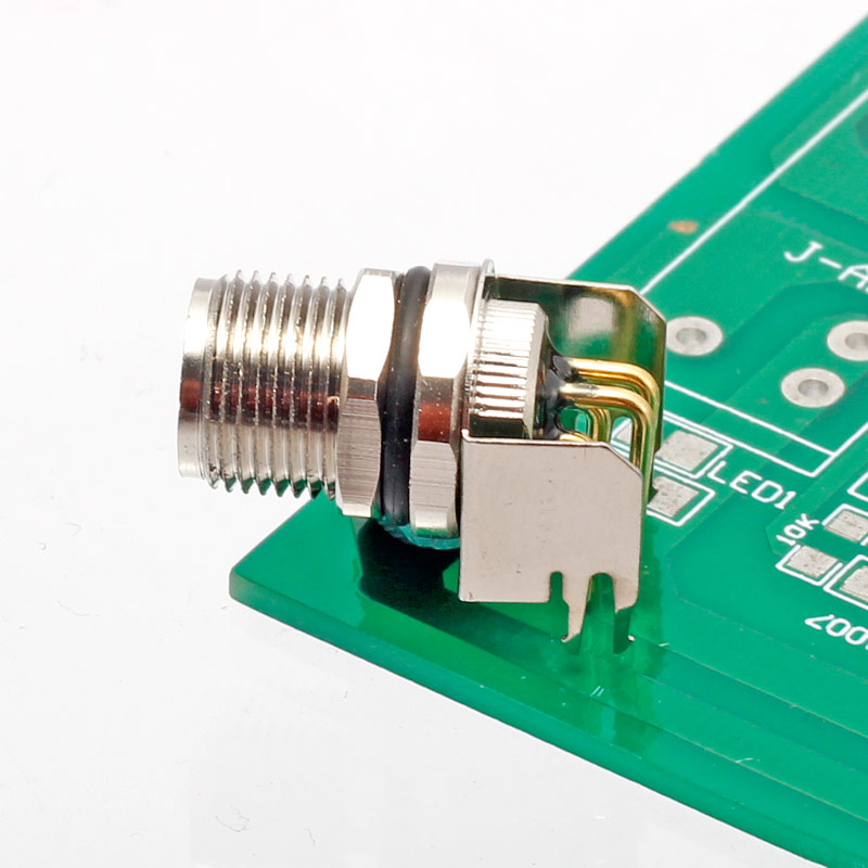
How to Press Collet Socket Component PCB?
Pressing a collet socket component onto a PCB requires care to avoid damaging the socket or the board. Collet sockets use a cylindrical, slotted collet that expands to grip a component pin.
- Tool Selection: Use a dedicated pressing tool or a hand press with a flat, non-marring tip. The correct tool ensures even force distribution.
- Alignment: Carefully place the collet socket over the target via or hole on the PCB. Ensure it is perfectly perpendicular to the board surface.
- Application of Force: Apply steady, vertical pressure to the top of the socket. Avoid rocking or applying angled force, which can bend the collet or damage the PCB pads.
- Seating Check: Press until the socket is fully seated against the PCB. You should feel a distinct stop. A visual inspection should show no gap between the socket’s base and the board.
- Post-Installation: After pressing, it is good practice to solder the retention tabs (if present) to the PCB for additional mechanical strength.
How to Add Sockets to Fabricated PCB?
Adding sockets to an already fabricated PCB is a common rework or modification technique.
- Preparation: Gather the correct PCB socket, soldering iron, solder, flux, and desoldering braid (if replacing an existing component).
- Site Preparation: If replacing a soldered component with a socket, first desolder and remove the original component. Clean the pads with desoldering braid to ensure they are flat and clear of old solder.
- Socket Placement: Insert the PCB pin socket into the holes. For small sockets, you can hold them in place by hand. For larger ones, use a piece of tape on the top to temporarily secure them.
- Soldering: Apply a small amount of flux to the pins. Solder one corner pin first to fix the socket’s position. Then, solder all the remaining pins, ensuring the solder flows smoothly and creates a clean fillet.
- Inspection and Cleaning: Visually inspect for bridges or cold solder joints. Use isopropyl alcohol to clean off any residual flux.
This process allows for upgrades, such as adding an arduino nano PCB socket for easy microcontroller replacement.
How to Check PCB Socket?
Knowing how to check PCB socket is vital for quality assurance. Here is a systematic approach:
- Visual Inspection: Check for physical damage like cracked body or bent pins. Verify correct orientation and full seating on the board.
- Continuity Test: Use a multimeter in continuity mode. Place one probe on the socket’s contact point and the other on the corresponding solder joint on the bottom of the PCB. A beep confirms a good connection through the socket to the board.
- Insertion/Extraction Test: Insert a known-good mating pin or plug into the socket. It should insert smoothly with a positive “click” or firm resistance and require a deliberate force to remove. This tests the mechanical grip of the PCB socket pins.
- Contact Resistance Test: For critical power or signal applications, use a multimeter to measure the resistance between the mating pin (inserted into the socket) and the PCB solder joint. A very low resistance (typically well below 1 ohm) indicates a good connection.
- Functional Test: The final check is to plug in the intended component (e.g., a chip, relay, or USB device) and verify that the system operates correctly.
All in all, a PCB socket is an indispensable component that bridges the gap between permanent soldering and the need for modularity and serviceability in electronics. This guide has detailed how to select, install, and verify various PCB socket connector types to ensure a reliable final product.
When sourcing these critical components, partnering with a trusted PCB and PCBA manufacturer is key for successful integration. BEST Technology specializes in high-precision PCB fabrication and assembly services, providing the essential foundation for reliably mounting all types of PCB sockets. Our expertise ensures that your board designs feature accurate footprints, proper solder mask definitions, and controlled soldering processes—all critical for the mechanical stability and electrical performance of every PCB socket connector you use. For a partner who ensures your sockets are mounted correctly from the start, rely on our manufacturing expertise. Pls feel free to contact us today at sales@bestpcbs.com to discuss your PCB and PCBA requirements.
You may also like


Tags: 2mm banana socket pcb mount, pc board connector, PCB Socket