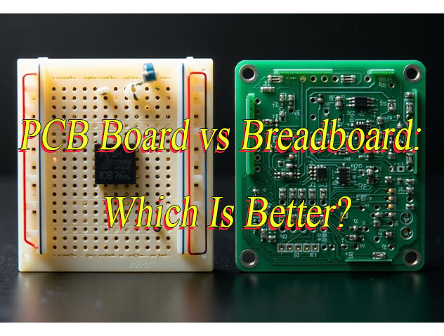
How to choose finished copper thickness PCB? Let’s discover finished copper thickness PCB’s definition, IPC standard, selection guide, measure methods and steps, difference between standard copper thickness.
Are you troubled with these issues?
- How to address PCB burnout due to insufficient copper thickness in high-current scenarios?
- How to resolve signal loss caused by copper thickness fluctuations during high-frequency signal transmission?
- How to tackle uneven heat dissipation and shortened lifespan due to localized thin copper thickness?
As a professional PCB manufacturer, EBest Circuit (Best Technology) can provide you service and solution:
- Precision Plating Process Optimization: Achieve ±5% uniformity in finished copper thickness, enhancing current-carrying capacity by 30% for high-current applications.
- Full-Process Copper Thickness Monitoring: Visualize per-batch copper thickness data via X-ray measurement, ensuring signal transmission loss stays below 3% for reliable high-frequency performance.
- Customized Thermal Management Design: Optimize copper thickness distribution and heat dissipation paths to boost thermal efficiency by 20% and extend product lifespan by 50%.
Welcome to contact us if you have any request for PCB manufacturing: sales@bestpcbs.com.
What is Finished Copper Thickness PCB?
Finished Copper Thickness PCB refers to the final measurable thickness of copper layers on a completed printed circuit board (PCB) after all manufacturing processes, including copper plating, etching, and surface finishing (like ENIG or HASL) are fully executed. This critical parameter determines the PCB’s current carrying capacity, signal integrity, and thermal performance, directly impacting the board’s electrical reliability and compliance with industry standards like IPC-6012. Unlike initial copper foil thickness, the finished value accounts for material added during plating or lost during etching, making it the true functional thickness for design validation.
IPC Standards for PCB Finished Copper Thickness
| IPC Standard | Finished Copper Thickness (Typical) |
| IPC-6012 Class 1 | 0.5 oz (17 µm) minimum for external layers; internal layers as specified by design but generally thinner |
| IPC-6012 Class 2 | 1.0 oz (35 µm) minimum for external layers; internal layers as specified by design but generally thinner |
| IPC-6012 Class 3 | 2.0 oz (70 µm) minimum for external layers; internal layers as specified by design but generally thinner |
| IPC-4562 | Specifies copper foil thickness ranges from 0.25 oz (9 µm) up to 4.0 oz (140 µm) and more for specific applications within the standard’s scope |
How to Choose the Right Finished Copper Thickness PCB?
Below is PCB finished copper thickness selection guide:
1. Define Application Scenarios and Current Requirements
- High-Current Applications: Power modules, motor drives, high-power LEDs, and other circuits carrying large currents require thicker copper layers (e.g., 2oz or higher).
- Example: For a 10A current, a 1oz copper thickness (35μm) needs a trace width of ~3mm, while 2oz (70μm) reduces it to just 1.5mm, saving space.
- Low-Current/Signal Transmission: Consumer electronics, sensors, and other signal-based circuits typically suffice with 1oz copper, balancing cost and manufacturing flexibility.
2. Evaluate Thermal Management Needs
- High-Heat Components: Power devices (e.g., MOSFETs, IGBTs) require thick copper for rapid heat dissipation to prevent localized overheating.
- Recommendation: Use 2oz or 3oz copper paired with thermal vias to enhance heat conduction.
- Low-Heat Scenarios: Standard digital or low-power analog circuits can function well with 1oz copper for thermal management.
3. Consider Signal Integrity (for High-Frequency Applications)
- High-Frequency Signal Transmission: Increased copper thickness may introduce parasitic inductance, degrading signal quality.
- Suggestion: Prioritize 1oz copper for frequencies >1GHz or high-speed digital circuits, combined with impedance-controlled designs.
- Low-Frequency Analog Circuits: Copper thickness has minimal impact, so select based on current requirements.
4. Balance Cost and Manufacturability
Cost Differences: Each additional 1oz of copper increases costs by ~10–20% (varies by manufacturer and volume).
Cost-Effective Choices:
- 1oz: Lowest cost, ideal for high-volume consumer electronics.
- 2oz: Good balance of cost and performance for industrial controls and automotive electronics.
- 3oz+: High cost, reserved for specialized applications (e.g., aerospace).
Process Limitations:
- Ultra-thick copper (>4oz) requires specialized lamination processes, potentially increasing lead times and reducing yield rates.
- Fine-pitch components (e.g., 0.4mm BGA) on thick copper boards may risk short circuits due to uneven etching.
5. Verify Mechanical Strength and Reliability
- Vibration/Shock Environments: Thick copper boards (≥2oz) offer greater rigidity, suitable for automotive, industrial equipment, or other vibrating environments.
- Repeated Connector Insertions: Thicker copper reduces the risk of copper foil delamination during plugging/unplugging.
- Testing Recommendation: Validate reliability under extreme conditions via HALT (Highly Accelerated Life Testing).
6. Assess Adaptability to Harsh Environments
- High-Temperature Settings: Thick copper’s lower CTE (Coefficient of Thermal Expansion) reduces solder joint stress, making it ideal for automotive engine compartments or outdoor equipment.
- Corrosive Environments: Thicker copper slows chemical corrosion but should be paired with surface finishes (e.g., ENIG, OSP) for enhanced protection.
7. Refer to Industry Standards and Case Studies
- Automotive Electronics: Typically require 2oz copper to meet AEC-Q100 reliability standards.
- Industrial Controls: 1.5oz–2oz copper balances cost and performance.
- Consumer Electronics: Prioritize 1oz for thinness and cost efficiency.
- Case Study: A power module overheated with 1oz copper but reduced temperature rise by 40% after switching to 2oz.
8. Consult Manufacturers and Use Simulation Tools
- Manufacturer Recommendations: Provide parameters like current, temperature rise, and space constraints to get tailored advice.
- Simulation Tools: Use PCB design software (e.g., Altium, Eagle) for current density and thermal simulations to optimize copper thickness.

How to Measure Finished Copper Thickness PCB?
Methods about how to measure PCB finished copper thickness:
1. Microsection Analysis Method
- Use precision cutting machine to extract PCB sample perpendicular to copper foil direction, ensuring smooth and damage-free cross-section.
- Embed sample in thermosetting resin, then grind sequentially with coarse-to-fine abrasive papers until surface is scratch-free.
- Perform mechanical polishing with diamond paste to eliminate surface stress, followed by slight chemical etching to enhance layer contrast.
- Measure copper thickness via metallurgical microscope or scanning electron microscope (SEM) using software scales or energy-dispersive spectroscopy, averaging multiple points for precision.
- Suitable for laboratory validation, standard establishment, and critical product certification, though destructive and time-consuming, requiring skilled operators.
2. Eddy Current Thickness Gauge Method
- Position probe vertically against copper surface after device activation, ensuring no air gaps or debris disrupt electromagnetic field.
- Calibrate zero point using standard thickness shims, adjusting gain to match measurement environment.
- Move probe slowly across target area; instrument displays thickness via impedance changes from eddy currents induced in copper layer.
- Avoid PCB edges, pad perimeters, and via surroundings to prevent geometric effects; regular calibration with shims maintains stability.
- Ideal for production line rapid testing of large copper areas, though sensitive to substrate properties, surface roughness, and temperature.
3. X-Ray Fluorescence Spectrometry (XRF) Method
- Configure XRF device with copper-specific X-ray excitation parameters, ensuring no spectral interference from other metals.
- Place sample under measurement window, adjusting focus to fully cover target area without exceeding copper foil boundaries.
- Device excites copper atoms to emit fluorescence, which is detected and quantified for thickness calculation.
- Requires pre-calibration using standard curves or certified reference samples, accounting for substrate density variations.
- Applicable for non-destructive testing of multilayer boards, surface finishes, and complex plating stacks, though equipment is costly and requires training.
4. Gravimetric Method
- Measure mass difference of defined copper area before/after etching using precision balance, ensuring no contamination or oxidation.
- Calculate average thickness via formula: Thickness = (Mass Difference) / (Area × Copper Density 8.96 g/cm?).
- Strict control of etching time and solution concentration prevents over-etching; results reflect bulk average, not local variations.
- Suitable for raw material acceptance and laboratory baseline verification, though destructive and unable to assess local thickness differences.
5. Micrometer Measurement Method
- Measure total thickness at PCB edges or dedicated test pads using micrometer, then subtract substrate thickness to derive copper thickness.
- Ensure measurement points are free of plating defects and foreign matter, with micrometer faces parallel to copper surface to minimize error.
- Useful for quick edge copper checks and simple structures, though accuracy is limited by operator technique and device resolution.
6. Optical Microscopy Method
- After preparing high-quality metallographic sample, measure copper thickness directly under optical microscope using eyepiece scale or software ruler.
- Adjust focus for clear imaging and measure multiple fields of view to reduce random error.
- Effective for observing cross-sectional structure and plating uniformity, though results depend on sample preparation quality and microscope calibration.
7. Ultrasonic Thickness Measurement Method
- Emit high-frequency ultrasonic pulses into copper layer, calculating thickness from reflection time differences.
- Calibrate sound velocity using reference samples and ensure couplant fully fills probe-copper interface to minimize signal loss.
- Suitable for non-planar geometries and complex shapes, though accuracy is affected by surface roughness and material acoustic properties.
8. Electrochemical Analysis Method
- Apply micro-current in electrolytic cell to induce copper dissolution/deposition, quantifying thickness via charge transfer measurements.
- Precisely control current density, electrolyte concentration, and reaction time for reproducible results.
- Ideal for thin copper layers and microvia structures, though requires specialized experimental conditions and safety protocols.
9. Microresistance Technique
- Measure copper layer resistance using four-point probe or dedicated resistometer, converting to thickness via copper resistivity relationships.
- Account for temperature compensation and contact resistance, ensuring good probe-to-copper contact without oxidation interference.
- Useful for surface copper and via thickness assessment, though demands high-precision instruments and complex calibration procedures.

Difference Between Standard Copper Thickness and Finished Copper Thickness
Definition and Composition
- Standard Copper Thickness: Refers to the thickness of the original copper foil on the substrate, excluding any additional copper layers from subsequent processes. Provided directly by suppliers, e.g., 1oz copper (approximately 35μm, 1.37mils) per IPC-4562 standards, 2oz copper (70μm, 2.74mils).
- Finished Copper Thickness: Refers to the final copper thickness after all manufacturing processes (plating, etching, etc.), including base copper and plated layers. For example, 1oz standard copper may increase to 35-45μm after plating, while 2oz may reach 70-90μm.
- Comparison: Standard thickness serves as the initial design reference, while finished thickness is the actual value post-processing, typically thicker and influenced by process parameters.
Measurement Stage
- Standard Copper Thickness: Measured during substrate production, using supplier-provided data (e.g., copper foil weight conversion to thickness, e.g., 1oz = 1 ounce per square foot ≈ 35μm).
- Finished Copper Thickness: Measured after PCB fabrication, considering factors like plating layers and etching losses. Verified via microscopy or thickness gauges to ensure compliance with design specifications (e.g., ±10% tolerance).
- Comparison: Standard thickness is determined early in production, while finished thickness reflects the final processed result.
Typical Values and Tolerance Ranges
- Standard Copper Thickness: Common values include 1oz (35μm, 1.37mils), 0.5oz (17.5μm, 0.68mils), or 2oz (70μm, 2.74mils), with supplier-controlled tolerances (e.g., ±5%).
- Finished Copper Thickness: Values vary with plating processes; e.g., 1oz standard may reach 35-45μm (±10% tolerance), 2oz may achieve 70-90μm (±15% tolerance).
- Comparison: Finished thickness often has wider tolerance ranges due to processing variables like etching and plating.
Application Scenarios and Performance Impact
- Standard Copper Thickness: Influences substrate selection and cost (e.g., 1oz for consumer electronics, 2-20oz for industrial power supplies). Thickness affects initial processing difficulty (thicker copper requires more complex processes).
- Finished Copper Thickness: Directly impacts circuit performance, e.g., current-carrying capacity (2oz copper: 3.5A vs. 1oz: 1.8A), thermal dissipation (≥2oz for high-current applications). Insufficient thickness may cause voltage drop, overheating, or failure.
- Comparison: Standard thickness affects material costs and manufacturability, while finished thickness determines circuit reliability and must be specified per application requirements.
Influencing Factors
- Standard Copper Thickness: Determined by supplier processes, substrate type (e.g., FR4, CEM-3), and foil weight (e.g., 1oz = 1 ounce per square foot).
- Finished Copper Thickness: Affected by plating parameters (current density, bath composition), etching conditions (rate, uniformity), design features (trace width/spacing), and lamination processes (temperature, pressure).
- Comparison: Standard thickness is primarily supplier-controlled, while finished thickness is influenced by both processing and design factors, introducing more variability.
Welcome to contact us if you’re still confused about the difference between standard copper thickness and finished copper thickness: sales@bestpcbs.com.