





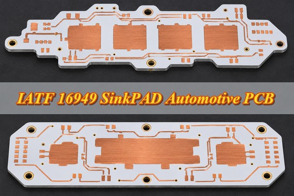
An IATF 16949 SinkPAD Automotive PCB can address the thermal bottleneck that appears when an automotive LED works perfectly during bench testing yet overheats inside a compact headlight housing. When the PCB’s dielectric layer limits heat transfer, a SinkPAD PCB provides a direct copper thermal path to improve heat dissipation.
EBest Circuit manufactures custom automotive SinkPAD PCBs, from single-layer to multilayer structures, with free DFM review, PCB assembly, and automotive quality support. The right solution starts with your LED’s thermal requirements, electrical connections, and mounting design.
Where Are SinkPAD PCBs Used in Automotive Thermal Management?
SinkPAD PCBs are primarily used in automotive LED lighting systems where high power density, concentrated heat, or limited cooling space makes temperature control difficult. They are particularly useful when conventional metal-core PCBs cannot meet the required LED junction temperature.
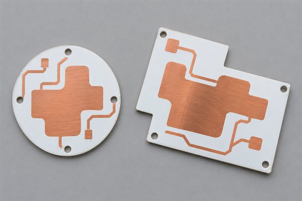
Common automotive applications include:
- Automotive LED Headlights: High-power LEDs generate concentrated heat during continuous operation. A copper-core SinkPAD PCB transfers heat from the LED thermal pad toward the headlight’s cooling structure, helping control junction temperature and maintain consistent light output.
- Matrix LED Headlights: Closely spaced LEDs create multiple heat sources within a compact assembly. SinkPAD structures provide direct thermal contacts beneath compatible LEDs, while multilayer circuits support more complex power distribution and control routing.
- Daytime Running Lights (DRLs): Limited installation space can restrict heat sink dimensions. A direct copper thermal path improves heat transfer beneath the LED without requiring additional PCB area.
- High-Output Rear Lighting: High-brightness tail lamps and signal lights may benefit from SinkPAD construction when sustained operation and elevated enclosure temperatures place greater demands on thermal management.
The suitability of SinkPAD depends on the LED package, operating power, mounting conditions, and available cooling capacity. These factors determine whether a direct thermal path is necessary for the lighting module.
How Does SinkPAD PCB Reduce Thermal Resistance in Automotive Electronics?
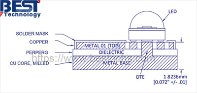
SinkPAD PCB reduces local thermal resistance by transferring heat from a compatible LED thermal pad directly into a raised copper pedestal, bypassing the insulating dielectric beneath that contact.
A conventional MCPCB uses a dielectric layer to separate electrical circuitry from the metal base. That layer provides insulation but also adds thermal resistance. SinkPAD construction removes the dielectric from designated thermal-contact regions while keeping the surrounding circuitry electrically insulated.
The direct thermal path provides three main benefits:
- Lower Local Thermal Resistance: Heat travels through the solder connection into the copper pedestal without crossing the dielectric directly beneath the thermal pad.
- Improved Heat Spreading: The copper base distributes heat away from the concentrated LED contact area toward the external heat sink or mounting surface.
- Better Junction-Temperature Control: Reducing thermal resistance can lower the LED temperature rise under the same operating conditions, helping limit heat-related changes in light output and long-term performance.
Copper has a thermal conductivity of approximately 400 W/(m·K). This describes the material itself, not the measured thermal resistance of the finished PCB or complete lighting module.
Thermal resistance for a defined heat path is calculated as:
Thermal Resistance (°C/W) = Temperature Difference (°C) / Heat Dissipation (W)
For an automotive LED, junction temperature also depends on the component package, solder joint, thermal interface material, heat sink, and ambient temperature. Thermal performance should therefore be evaluated under the intended operating conditions rather than judged by copper conductivity alone.
SinkPAD PCB vs. Standard MCPCB: Which Should You Choose for Automotive Applications?
SinkPAD PCB is a suitable choice when a compatible high-power LED requires lower local thermal resistance than a conventional MCPCB can provide. A standard MCPCB remains appropriate when its thermal and electrical performance already satisfies the design requirements.
| Comparison | Standard MCPCB | SinkPAD PCB |
|---|---|---|
| Thermal Path | Heat passes through the insulating dielectric | Heat bypasses the dielectric beneath the designated thermal pad |
| Local Thermal Resistance | Includes dielectric thermal resistance | Reduces resistance in the direct-contact region |
| Electrical Isolation | Circuit copper is normally insulated from the metal core | Direct-contact thermal pad must be electrically compatible with the copper core |
| Manufacturing Complexity | Conventional metal-core processing | Requires copper pedestal fabrication and dimensional control |
| Component Requirements | Suitable for a wide range of insulated layouts | Requires verification of the component’s thermal-pad potential |
| Suitable Applications | LED modules meeting their temperature targets | High-power LED modules requiring improved local heat transfer |
For a compact automotive headlight approaching its allowable junction-temperature limit, SinkPAD may provide an advantage without increasing PCB dimensions. However, its benefit depends on whether the remaining cooling system can remove the transferred heat.
A meaningful comparison should use the same LED, dissipated power, ambient temperature, and heat sink configuration.
Which SinkPAD PCB Structures and Materials Suit Automotive LED Designs?
Automotive SinkPAD PCB structures should be selected according to circuit complexity, thermal-contact requirements, electrical isolation, and installation space. Single-layer construction is suitable for simpler LED circuits, while additional layers accommodate more demanding routing.
| SinkPAD Structure | Construction | Suitable Automotive Application |
|---|---|---|
| Single-Layer SinkPAD PCB | One circuit layer with a copper core and direct thermal contacts | High-power LED modules with straightforward circuitry |
| 2-Layer SinkPAD PCB | Two circuit layers on the same side of the copper core | Compact lighting modules requiring additional routing |
| Multilayer SinkPAD PCB | Multiple circuit layers combined with direct thermal-contact regions | Matrix LED lighting and more complex electronic circuits |
| Double-Sided SinkPAD PCB | Circuit structures on both sides of a copper core | Specialized modules requiring two-sided component placement |
Material selection affects thermal behavior, electrical insulation, and mechanical reliability.
- Copper Core Thickness: The copper base provides heat spreading and structural support. Its thickness should match the thermal load, board dimensions, mounting arrangement, and weight restrictions.
- Dielectric Material: The insulating layer must withstand the required electrical voltage and operating temperature while maintaining adhesion between the circuit structure and copper core.
- Circuit Copper Weight: Trace width and copper thickness should support the required current without compromising conductor spacing or routing density.
- Surface Finish: ENIG, ENEPIG, immersion tin, and OSP provide different solderability, storage, and assembly characteristics. The finish should match the LED package and manufacturing process.
For double-sided and multilayer SinkPAD constructions, layer interconnections must be considered early. A solid copper core does not allow conventional plated through-holes to be used in the same way as a standard FR-4 multilayer PCB without an appropriately engineered structure.
The simplest construction that meets the electrical, thermal, and mechanical requirements is generally the most practical starting point.
What Automotive SinkPAD PCB Design Challenges Matter, and How Can They Be Solved?
Reliable automotive SinkPAD PCB design requires careful control of electrical compatibility, copper pedestal dimensions, soldering geometry, insulation, and mechanical stress. These factors directly affect heat transfer and assembly reliability.
- Electrically Active LED Thermal Pads: Some LEDs have thermal pads connected internally to electrical terminals. If components at different potentials share a conductive copper core, an unintended electrical connection may occur. Check the LED datasheet and schematic before assigning direct thermal contacts. Use an insulated alternative where electrical separation is required.
- Copper Pedestal Height Mismatch: An excessively high pedestal may prevent the surrounding solder pads from seating correctly, while a low pedestal may weaken thermal contact. Determine the required height from the LED package dimensions, circuit-layer construction, and solder-joint geometry. Specify the tolerance on the manufacturing drawing.
- Thermal-Contact Misalignment: Poor registration between the copper pedestal and LED thermal pad reduces contact area and may interfere with nearby conductors. Define pedestal position and clearance requirements, then verify them through finished-board dimensional inspection.
- Insufficient Circuit-to-Core Insulation: Direct thermal contact must not compromise insulation around unrelated power or signal traces. Select suitable dielectric materials and conductor clearances based on the circuit’s operating and transient voltages.
- Thermal Cycling and Solder Fatigue: Copper, dielectric materials, solder, and LED packages expand at different rates. Repeated heating and cooling can create mechanical stress. Suitable material selection, mounting support, and environmental testing help evaluate joint reliability.
- Poor Heat Sink Contact: Even an effective copper pedestal cannot compensate for an inadequate board-to-heat-sink interface. Control PCB flatness, mounting pressure, thermal interface material, and contact area to maintain the intended heat-transfer path.
For matrix LED modules, the electrical compatibility of multiple thermal contacts deserves particular attention. Sharing one copper base is only appropriate when the resulting electrical connections are consistent with the circuit design.
What Are EBest Circuit’s Automotive SinkPAD PCB Manufacturing Capabilities?
EBest Circuit manufactures custom copper-core SinkPAD PCBs in single-layer, two-layer, and multilayer structures, with direct thermal-contact designs for high-power LED applications.
| Manufacturing Parameter | Single-Layer SinkPAD PCB | 2-Layer SinkPAD PCB | Multilayer SinkPAD PCB |
|---|---|---|---|
| Base Material | Copper | Copper | Copper |
| Copper Core Thickness | 0.8, 1.0, 1.2, 1.4, 1.5 mm | 0.8, 1.0, 1.2, 1.4, 1.5 mm | 1.2, 1.4, 1.5, 1.6 mm |
| Finished Board Thickness | 1.0–2.0 mm | 1.0–2.0 mm | 1.6–2.0 mm |
| Circuit Copper Weight | 0.5, 1, 2 oz | 0.5, 1, 2 oz | 0.5, 1, 2, 3 oz |
| Surface Finish | ENIG, ENEPIG, Immersion Tin, OSP | ENIG, ENEPIG, Immersion Tin, OSP | ENIG, ENEPIG, Immersion Tin, OSP |
| Solder Mask Colors | White, Black, Blue, Green, Red | White, Black, Blue, Green, Red | White, Black, Blue, Green, Red |
| Outline Processing | Routing, Punching, V-Cut | Routing, Punching, V-Cut | Routing, Punching, V-Cut |
| Maximum Panel Size | 600 × 500 mm | 600 × 500 mm | 600 × 500 mm |
For automotive LED projects requiring thicker circuit copper, EBest Circuit also supports custom heavy-copper options, including special 3–10 oz requirements for single-layer and two-layer SinkPAD constructions after engineering review.
Custom SinkPAD fabrication can accommodate different copper pedestal shapes, LED footprints, circuit layouts, and mounting requirements. Critical characteristics include:
- Copper pedestal dimensions, height, and position.
- Circuit-to-core electrical insulation.
- Dielectric openings and layer registration.
- Finished-board thickness and flatness.
- Thermal-pad geometry and solderable surface finish.
These manufacturing options support both relatively simple automotive LED modules and more complex layouts requiring additional circuit layers.
How Are Automotive SinkPAD PCBs Manufactured and Assembled?
Automotive SinkPAD PCB manufacturing combines copper pedestal fabrication with insulated circuit processing, while assembly focuses on accurate LED placement and controlled soldering. Both stages are important to the final thermal-contact quality.
SinkPAD PCB Manufacturing Process
- Gerber and Stackup Preparation: Separate the electrical circuit features from the designated LED thermal-contact regions. Define the copper pedestal geometry, dielectric openings, and layer alignment requirements before fabrication.
- Copper Core Processing: Clean and pattern the copper substrate, then selectively etch the surrounding copper to create raised thermal-contact regions. Control pedestal dimensions and height according to the approved drawing.
- Circuit Layer Fabrication: Produce the required conductor patterns with the specified copper weight and layer construction. Form openings corresponding to the copper thermal contacts and prepare any necessary interconnections.
- Alignment and Lamination: Align the circuit structure with the copper core so the designated contact regions match the pedestal positions. Laminate the layers while preserving the required electrical insulation around the circuitry.
- Solder Mask and Surface Finishing: Apply the selected solder mask and surface finish to protect the circuit and maintain solderability at the component mounting areas.
- Board Profiling and Inspection: Complete routing, punching, or V-cut processing according to the mechanical drawing. Inspect electrical continuity, insulation, board dimensions, and critical copper pedestal characteristics before assembly.
Automotive SinkPAD PCB Assembly Process
- Solder Paste Printing: Use a stencil designed around the LED land pattern and thermal-pad geometry. Control solder-paste volume to achieve consistent joint formation without excessive solder accumulation.
- Component Placement: Position LEDs, drivers, sensors, and other components using the approved assembly data. Accurate alignment between the LED thermal pad and copper pedestal is essential for reliable contact.
- Reflow Soldering: Develop a reflow profile for the actual copper-core assembly. The copper base absorbs considerable heat, so solder-paste requirements, component temperature limits, and temperature distribution across the board must be controlled.
- Solder-Joint Inspection: Use appropriate inspection methods, including AOI and X-ray where the package or solder-joint structure requires it, to identify placement errors, solder defects, and relevant hidden-joint problems.
- Electrical and Functional Testing: Verify the assembled circuit’s operation, including LED output and applicable driver or control functions, under the agreed test conditions.
The PCB fabrication stage establishes the copper thermal path. The assembly stage must create a suitable solder connection between the LED thermal pad and that path without damaging the component or surrounding circuit structure.
How Are Automotive SinkPAD PCBs Tested for Thermal and Long-Term Reliability?
Automotive SinkPAD PCB reliability is verified through electrical, dimensional, thermal, and environmental tests based on the product’s operating conditions and customer requirements.
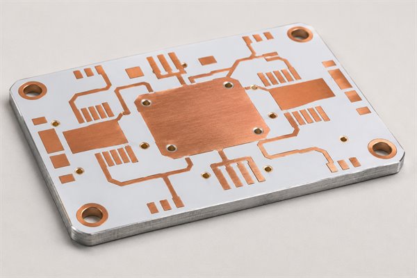
Important inspection and validation methods include:
- Electrical Continuity Testing: Checks for open circuits, short circuits, and incorrect connections against the approved circuit netlist.
- Insulation Testing: Verifies electrical separation between specified circuit networks and the copper core using the required test voltage and acceptance limits.
- Copper Pedestal Inspection: Measures pedestal dimensions, location, height, and coplanarity to confirm compatibility with the LED mounting geometry.
- Structural Inspection: Uses cross-section examination where necessary to evaluate internal connections, dielectric interfaces, and multilayer construction.
- Thermal Performance Testing: Measures temperatures at defined locations while the LED module operates at specified power and ambient conditions.
- Environmental Reliability Testing: Evaluates the effects of temperature cycling, thermal shock, vibration, humidity, and other stresses specified for the automotive application.
Thermal testing should identify the LED package, operating current, voltage, dissipated power, ambient temperature, heat sink configuration, and measurement locations.
For example, a lighting module tested with an exposed laboratory heat sink may behave differently when installed inside a sealed vehicle headlight. The cooling arrangement used for validation should reflect the intended operating environment.
After environmental testing, the relevant electrical, structural, and solder-joint characteristics are checked against the approved acceptance criteria to determine whether the assembly has maintained its required performance.
What Is the Lead Time for Automotive SinkPAD PCB Prototypes and Mass Production?
Automotive SinkPAD PCB lead time depends on layer count, copper pedestal complexity, material requirements, and the inspection scope. EBest Circuit offers the following manufacturing schedules for standard SinkPAD structures.
Single-Layer SinkPAD PCB
- Prototype Lead Time: 1.5–2 weeks
- Mass Production Lead Time: 2–3 weeks
2-Layer SinkPAD PCB
- Prototype Lead Time: 1.5–2 weeks
- Mass Production Lead Time: 2–3 weeks
Multilayer SinkPAD PCB
- Prototype Lead Time: 3–4 weeks
- Mass Production Lead Time: 4–6 weeks
Single-layer and two-layer SinkPAD PCBs can follow similar production schedules, while multilayer construction generally requires additional circuit fabrication and alignment operations.
Special copper pedestal geometries, heavy copper requirements, additional inspections, and customer qualification activities can affect the project schedule.
PCB assembly, customer approval, and international transportation are arranged according to the complete order requirements.
How Can Automotive SinkPAD PCB Prototypes Move into Stable Mass Production?
Stable production depends on maintaining the approved PCB design, materials, manufacturing process, and inspection criteria after prototype validation. This helps prevent unwanted differences between development samples and subsequent production batches.
The key controls include:
- Approved Design Revisions: Maintain controlled specifications for copper-core thickness, dielectric materials, circuit stackup, surface finish, and critical mechanical dimensions.
- Critical Process Control: Monitor manufacturing characteristics that affect thermal contact, electrical insulation, and mechanical fit, including copper pedestal geometry, circuit registration, and finished-board thickness.
- Production Approval: Complete the applicable first-article inspections and customer approval activities. Automotive programs may require APQP, PPAP, PFMEA, Control Plans, and supporting manufacturing records.
- Material and Batch Traceability: Link production batches to relevant raw materials, processing information, and inspection results so nonconforming products can be identified and investigated.
- Manufacturing Change Control: Evaluate changes to approved materials, processes, tooling, or production locations and obtain customer approval when required.
IATF 16949 supports automotive manufacturing through process control, risk prevention, traceability, and corrective-action requirements.
For automotive supplier qualification, customers can review the applicable IATF 16949 certificate and confirm the required inspection records, traceability scope, and production approval documentation with EBest Circuit.
The purpose is to maintain the same approved thermal, electrical, and mechanical characteristics throughout repeat production.
Why Choose EBest Circuit for Automotive SinkPAD PCB Thermal Solutions?
EBest Circuit helps automotive lighting manufacturers reduce design revisions, simplify PCB sourcing and assembly, and maintain consistent requirements from prototyping to production.
- Avoid Unnecessary Prototype Revisions: Free DFM review helps identify copper pedestal alignment issues, thermal-pad incompatibility, insulation problems, and assembly risks before fabrication. Early engineering feedback can reduce repeated design changes.
- Get a SinkPAD Structure Matched to Your LED Package: Custom single-layer, two-layer, and multilayer copper-core designs accommodate different component footprints, circuit layouts, and mounting arrangements. The PCB can be manufactured around the actual product requirements rather than a fixed standard design.
- Support Automotive Supplier Qualification: EBest Circuit offers automotive quality-system support, including access to applicable IATF 16949 and ISO 9001 certification information. Project-specific inspection, traceability, and production approval requirements can be coordinated during qualification.
- Reduce Coordination Between PCB and Assembly Suppliers: PCB fabrication, component sourcing, SMT assembly, and applicable testing can be managed within one project, reducing communication gaps between bare-board manufacturing and final assembly.
- Maintain Continuity from Prototype to Production: Engineering support and controlled manufacturing requirements help carry approved PCB specifications into subsequent batches, limiting avoidable changes to the thermal structure and assembly process.
FAQs About IATF 16949 SinkPAD Automotive PCBs
Q1: Can an NTC thermistor be integrated into an automotive SinkPAD PCB?
A1: Yes. An NTC thermistor can monitor local PCB temperature near a high-power LED. Its position should be evaluated to establish the relationship between the measured temperature and the LED’s thermal behavior.
Q2: Can automotive SinkPAD PCBs use white solder mask?
A2: Yes. White solder mask is available for reflective LED lighting designs. The selected material should provide suitable reflectivity retention, temperature resistance, and environmental performance.
Q3: Does LED forward voltage variation affect thermal performance?
A3: Yes. Changes in forward voltage and operating current affect electrical input power and can influence the heat generated by the LED. Thermal evaluation should cover the expected component tolerances and operating conditions.
Q4: Can automotive SinkPAD PCB assemblies receive conformal coating?
A4: Yes, when the coating is compatible with the components and operating environment. Optical surfaces, connectors, and designated heat-transfer interfaces may require masking.
Q5: How should bare SinkPAD PCBs be stored before LED assembly?
A5: Store them according to the surface finish and packaging requirements. Protect solderable contacts from contamination, oxidation, excessive humidity, and handling damage.
Q6: Can high-power LEDs be reworked on copper-core SinkPAD PCBs?
A6: Rework may be possible using suitable heating equipment and a validated temperature profile. The copper core’s thermal mass must be considered to avoid damage to neighboring components, insulation, or solder joints.
Q7: Does AEC-Q102 apply to bare automotive SinkPAD PCBs?
A7: No. AEC-Q102 applies to automotive optoelectronic semiconductor devices, including LEDs. Bare PCB and complete-module qualification follow their respective applicable specifications and customer requirements.
Q8: Can automotive SinkPAD PCB assemblies be cleaned after soldering?
A8: Yes, provided the cleaning materials and process are compatible with the LEDs, solder mask, surface finish, and other components. Cleaning and drying conditions should prevent material damage and residual contamination.
How Can You Get a Custom Automotive SinkPAD PCB Quote?
For an IATF 16949 SinkPAD Automotive PCB quote, EBest Circuit provides custom automotive SinkPAD PCB manufacturing, copper-core thermal solutions, free DFM review, and optional PCB assembly services for high-power automotive lighting. Send your Gerber files, LED part numbers, thermal-pad specifications, PCB dimensions, proposed stackup, and relevant testing or quality requirements. Include your quantity, required delivery date, and delivery location so our team can review manufacturability and confirm the project lead time. Contact sales@bestpcbs.com for engineering support and a custom quotation.
You may also like




Tags: automotive LED PCB, Automotive SinkPAD PCB, direct thermal path pcb, iatf 16949 pcb