How to use the MCP73831? Let’s discover benefits, usage guide, selection guide, difference between TP4056, datasheet and cost for MCP73831.
Are you worried MCP738317 about these questions?
- Time-consuming selection and debugging?
- Inconsistent batch performance?
- High costs for small-batch procurement?
- Plug-and-Play Module Verification: Pre-configured MCP73831 evaluation board with preset R_PROG resistor + thermal layout optimization. Test CC/CV transition curves immediately upon arrival, reducing debugging cycle by ≥2 weeks and eliminating trial-and-error.
- End-to-End Parameter Calibration: Post-SMT charging current calibration + float voltage verification for each PCBA, with test reports provided. Ensures batch-to-batch consistency with ≤±0.5% parameter error, enhancing stability by 30%.
- One-Stop BOM Optimization: Consolidated supply chain for MCP73831 and peripheral components, offering market-validated alternative materials. Reduces total cost by 15-20%, shortens lead time to 3-5 days, and simplifies BOM management.
Welcome to contact us if you have any request for MCP73831: sales@bestpcbs.com.
What Is MCP73831?
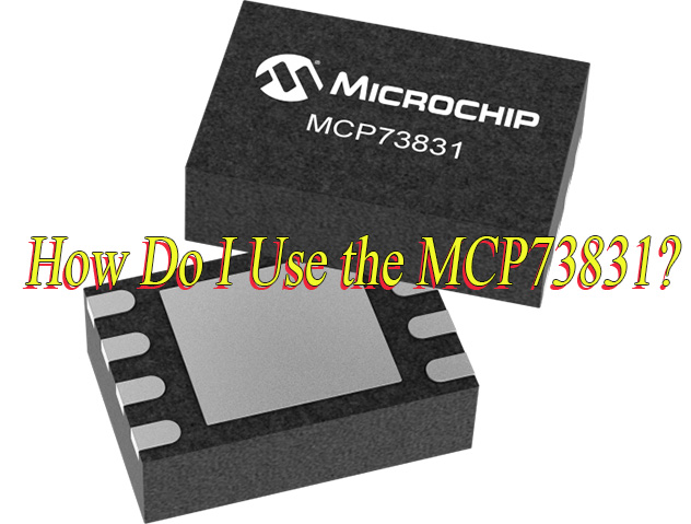
The MCP73831 is a complete linear charging management chip manufactured by Microchip for single-cell lithium-ion or lithium-polymer batteries. It integrates the necessary functional modules and requires minimal external components to intelligently manage the entire battery charging process (including trickle pre-charge, constant current fast charge, and constant voltage full charge stages), automatically terminating charging upon completion and providing charging status indication. It is a highly integrated and easy-to-use battery charging solution.

What Are the Benefits of Using MCP73831?
- Highly Integrated Design: Integrates charging controller, power MOSFET, current sensing, and safety protection circuits into a single chip, significantly reducing external components, lowering BOM cost, and minimizing PCB footprint.
- Complete Charging Management: Automatically executes a lithium battery-compliant Trickle → Constant Current (CC) → Constant Voltage (CV) charging algorithm, terminating automatically upon completion without requiring MCU intervention.
- Wide Input Voltage Compatibility: Supports 3.75V to 6.0V input range, perfectly compatible with 5V USB power sources (Type-A ports, adapters, power banks), simplifying power supply design.
- Multi-Layer Safety Protection: Built-in Over-Voltage Protection (OVP), battery reverse polarity protection, thermal regulation, and over-temperature shutdown to ensure system reliability.
- Configurable Charging Current: Flexibly sets constant current charging current (15mA–500mA range) via a single external resistor, adapting to various battery capacities.
- Low Power Standby Mode: Battery leakage current is typically <2µA when no input power is present, maximizing battery standby time.
- Real-Time Status Indication: Open-drain STAT pin provides Charging/Complete/Suspend status signals, enabling direct monitoring via LED or MCU.
How Do I Use the MCP73831?
1. Hardware Connection and Basic Configuration
- Power Input: Connect VIN pin to a 5V USB power source (compliant with USB standards). Parallel a ceramic capacitor ≥4.7μF for input filtering to ensure stable input voltage within 3.75-6V range.
- Battery Connection: Directly connect VBAT pin to the positive terminal of a single-cell lithium battery, with the negative terminal connected to VSS (GND). Parallel a capacitor ≥4.7μF at the output for stable charging voltage.
- Current Programming: Series a precision resistor (e.g., 2kΩ for 500mA charging current) between PROG pin and GND. Formula: I_CHARGE = 1000 / R_PROG (unit mA, R_PROG unit kΩ).
2. Charging Mode Control Logic
- Pre-charge Phase: When battery voltage <3V, the chip automatically enters pre-charge mode, charging at 10% of the set current (e.g., 50mA for 500mA setting) to prevent damage to deeply discharged batteries.
- Constant Current Fast Charging: When battery voltage ≥3V, switch to constant current mode, charging rapidly at the set current (e.g., 500mA) until voltage approaches 4.2V.
- Constant Voltage Termination: At 4.2V (±0.75% accuracy), switch to constant voltage mode. Current gradually decays to 5-10% of the set value before charging stops, with STAT pin outputting high level.
3. Status Monitoring and Feedback
STAT Pin Output:
- Low level (charging): Red LED lights or MCU reads low signal.
- High level (full): Green LED lights or triggers MCU completion interrupt.
- High-impedance state (shutdown/fault): Combine with power detection to avoid misjudgment.
Extended Applications: Connect STAT pin to MCU GPIO for software logic-based OLED battery display, Bluetooth App push, or voice alerts (e.g., “Charging complete”).
4. Protection and Safety Mechanisms
- Thermal Management: Built-in thermal regulation reduces current when junction temperature >150°C. For DFN packages, increase GND pad area and widen PCB copper traces for heat dissipation.
- Reverse Protection: Internal MOSFET cuts off during battery polarity reversal to prevent short circuits. Series a Schottky diode (≈0.3V drop) for enhanced protection.
- Under-Voltage Lockout (UVLO): Shuts down charging when input voltage <3.38V to prevent reverse battery discharge. Restart requires voltage rise above 3.45V.
5. Parameter Optimization and Design Specifications
- Current Selection: Set current based on battery capacity (e.g., 1000mAh) and charging time requirements (e.g., 0.5C = 500mA). Max not exceed 1A to avoid overheating.
- Capacitor Selection: Prefer X7R ceramic capacitors (low ESR) with voltage rating ≥10V for high-frequency stability.
- Layout Considerations: Shorten high-current paths (VIN→VBAT) to minimize parasitic inductance. Maintain a complete GND plane to reduce ground noise affecting charging accuracy.
6. Troubleshooting and Debugging
- Overheating Issues: Check input-output voltage differential (e.g., 1.3W power at 5V input). Optimize thermal design; reduce charging current or add heat dissipation holes if necessary.
- Charging Failure: Verify PROG resistor accuracy (1% metal film), STAT signal stability (add RC filter), and double-check VBAT voltage via ADC.
- Compatibility Issues: For different battery types (e.g., Li-Po requiring 4.35V full charge), select corresponding chip versions (MCP73831-3/4/5).
7. Extended Function Development
- Multi-Mode Adjustment: Switch between fast/standard/trickle modes via DIP switch or digital potentiometer (e.g., MCP4018) controlled by MCU.
- Intelligent Temperature Control: Monitor battery temperature with NTC thermistor; dynamically adjust R_PROG via MCU for adaptive charging (reduce current at high temps, increase at low temps).
- Long-Term Monitoring: Set maximum charging time (e.g., 6-hour timeout alarm) via software to prevent sustained faults causing overheating.

MCP73831 Datasheet
| Parameter | Specification/Range |
| Package | 5-Lead SOT-23, 8-Lead DFN (2mm×3mm) |
| Input Voltage VDD | 4.5V to 6V (Minimum Operating Voltage 3.75V) |
| Output Voltage (Battery Regulation Voltage) | 4.20V, 4.35V, 4.40V, 4.50V |
| Programmable Charge Current | 15mA to 500mA |
| Current Programming Formula | IREG = 1000 / RPROG (mA, RPROG in kΩ) |
| Precharge Threshold | 2.8V |
| Precharge Current | 10% of Programmed Fast Charge Current |
| Charge Termination Condition | Current Drops to 5%-20% of Programmed Value |
| Operating Temperature Range | -40°C to +85°C |
| Thermal Regulation | Automatically Limits Charge Current Based on Chip Temperature |
| Status Indication Output | Tri-State Output (High/Low/High-Impedance) |
| Reverse Discharge Protection | Integrated |
| Undervoltage Lockout (UVLO) | Shuts Down When Input Voltage Below Threshold |
MCP73831 vs TP4056: Which Is Better?
Charging Mode and Current Capability
- TP4056: Employs constant current/constant voltage (CC/CV) linear charging mode, supporting a maximum charging current of 1A (configured via PROG pin with external resistors, e.g., 2kΩ for 500mA, 1.2kΩ for 1A). Ideal for consumer electronics requiring fast charging (e.g., Bluetooth headsets, mini speakers).
- MCP73831: Also linear charging, but offers more flexible current configurations (e.g., 500mA/1A variants). Some models integrate power path management, enabling “charge-while-using” functionality. Suitable for devices demanding high charging stability (e.g., medical devices, premium portable instruments).
Accuracy and Protection Features
- TP4056: Full charge voltage accuracy ±1%. Built-in over-temperature, over-voltage, reverse polarity protection, and automatic recharge. Lacks real-time battery status monitoring (e.g., voltage/temperature feedback), relying on hardware-based automatic management.
- MCP73831: Accuracy up to ±0.5%. Integrates enhanced protection mechanisms (e.g., dynamic thermal regulation, timeout protection, auto-restart). Supports I²C interface for software-level monitoring, ideal for high-reliability scenarios (e.g., industrial equipment, smart hardware).
Cost and Package Design
- TP4056: Extremely low cost (approx. ¥0.3). Uses SOT-23-5 package with minimal peripheral components (2 capacitors + 1 resistor). BOM cost advantage makes it suitable for mass-produced, cost-sensitive products (e.g., toys, e-cigarettes).
- MCP73831: Slightly higher price but higher integration (e.g., built-in MOSFET and current sensing). Compact package (e.g., DFN-8) suits space-constrained premium devices. Long-term usage benefits from high accuracy, extending battery lifespan.
Thermal Management and Heat Dissipation
- TP4056: Linear architecture leads to high power dissipation (higher dropout voltage increases heat). Requires large copper areas, vias, or reduced current (e.g., prioritize 500mA) to avoid overheating. Measured power dissipation: ~0.65W at 5V input, 3.7V battery, 500mA current. Caution needed in enclosed environments.
- MCP73831: Built-in dynamic thermal regulation. Automatically reduces current when junction temperature exceeds 125°C, preventing thermal runaway. Suitable for high-temperature or enclosed scenarios (e.g., automotive devices, smart locks).
Application Scenario Adaptability
- TP4056: Optimal for cost-sensitive, speed-prioritized consumer electronics (e.g., power banks, IoT nodes). “Plug-and-play” design simplifies development but requires external protection chips (e.g., DW01A + FS8205) for over-discharge/short-circuit protection.
- MCP73831: Suited for devices requiring high safety and longevity (e.g., POS machines, portable medical devices). Precise charging curves reduce battery degradation, extending cycle life. Supports status pins for MCU integration, enabling smart status feedback.
Extensibility and Compatibility
- TP4056: Basic charging functionality only; requires external circuits for additional protections (e.g., under-voltage detection). Compatible with Micro-USB/Type-C inputs.
- MCP73831: Some models support power path management, allowing devices to operate directly from charger power during low battery. I²C interface enables communication with host controllers for dynamic charging strategy adjustments.
How to Choose A MCP73831 Battery Charging?
A detailed selection guide about MCP73831 battery charging:
1. Define Application Scenarios and Requirements
- Device Type: Determine whether the charger is for portable devices (e.g., smart speakers, Bluetooth headsets, AI chessboards), industrial equipment, or medical devices. International customers often prioritize minimized design (SOT-23-5 package measuring 2.9mm×1.6mm) and low power standby features.
- Battery Parameters: Confirm battery type (Li-ion/Li-polymer), voltage (e.g., 4.2V standard or 4.35V high-capacity), capacity (e.g., 1200mAh), and charging current requirements (15mA–500mA programmable).
- Environmental Adaptability: Consider operating temperature range (-40°C to +85°C), thermal management (e.g., enclosed enclosures requiring thermal regulation), and certification standards (RoHS3, CE, FCC, etc.).
2. Match Core Technical Parameters
- Input Voltage: Must be compatible with USB power (5V±0.25V) or external power supplies (4.5V–6.5V) to ensure stable input and avoid voltage fluctuations affecting charging efficiency.
- Charging Modes: Adopt Constant Current-Constant Voltage (CC-CV) algorithm supporting pre-charge, fast charge, and constant voltage phases. Pre-charge threshold can be set to 64%–74% of battery voltage to prevent deep discharge damage.
- Programmable Current: Set charging current via external resistor RPROG (formula: I_charge = 1200/RPROG in mA). For example, 450mA charging requires RPROG=2.67kΩ (recommended 1% tolerance metal film resistor).
- Voltage Regulation Options: Four-level selection (4.20V, 4.35V, 4.40V, 4.50V) to accommodate emerging high-capacity battery needs.
3. Critical Features and Protection Mechanisms
- Safety Features: Built-in thermal protection (automatic current reduction at 125°C junction temperature), reverse discharge prevention, soft start, and undervoltage lockout (UVLO). International customers emphasize thermal regulation capabilities (dynamic current reduction to prevent thermal runaway).
- Status Indication: The STAT pin supports three-state outputs, enabling LED or MCU-driven charging status visualization (e.g., red during charging, green when complete).
- Package and Layout: SOT-23-5 or DFN packages suit compact designs, requiring BAT pin trace width ≥0.5mm (2oz copper) and large ground planes for enhanced heat dissipation.
4. Compatibility and Extensibility
- Power Path Management: Supports load sharing designs (e.g., MCP73831+MOSFET solutions) enabling simultaneous charging and usage without load interference.
- Software Collaboration: MCUs can read STAT pin levels via GPIO, combining VIN detection for dual-state judgment (charging/complete/power-off) and real-time status push via Bluetooth/APP.
- Extended Components: Recommended pairing with TVS diodes (ESD protection), Schottky diodes (reverse polarity protection), and temperature sensors for dual-layer protection.
5. Supplier and Cost Considerations
- Supplier Selection: Prioritize international brands (e.g., Microchip, Digi-Key) for supply chain stability and technical support. Note lead times (e.g., standard 6 weeks, custom requirements require confirmation).
- Cost Optimization: Bulk purchases reduce unit costs (e.g., $0.66 per unit for 3000+ pieces), balancing BOM costs with performance needs. International customers focus on long-term reliability to avoid low-cost, low-quality solutions.
- Certifications and Standards: Confirm compliance with target market regulations (e.g., EU CE, US FCC) and provide RoHS3 compliance certificates and MSL1 moisture sensitivity level reports.
6. Verification Testing and Debugging
- Circuit Testing: Use ADC to measure shunt resistor voltage, validating charging current accuracy (e.g., 438mA measured vs. 450mA theoretical, ±3% tolerance).
- Environmental Testing: Validate charging performance and thermal regulation under high (45°C)/low (-40°C) temperature environments to ensure stability under extreme conditions.
- Troubleshooting: Address common issues (e.g., failure to start charging, LED misjudgment) through software logic (e.g., VIN+STAT dual detection) or hardware improvements (e.g., adding filter capacitors).
7. Regulatory Compliance and Long-Term Technical Support
- Global Regulatory Adaptation: For diverse target markets (e.g., EU, US, Japan), ensure compliance with local regulations (e.g., EU CE-EMC/LVD, US FCC Part 15, Japan PSE) and provide multilingual compliance documents (e.g., English/French/German test reports). International customers value traceable certifications, requiring unique serial numbers and compliance certificates per batch.
- Environmental Sustainability: Prioritize lead-free (Pb-free) solder and recyclable packaging materials, meeting RoHS3 halogen-free requirements and WEEE directives. Recommend detachable battery compartment designs for user-replaceable batteries and electronic waste recycling, aligning with circular economy trends.
- Long-Term Technical Support System: Select suppliers offering global warranty services (e.g., Microchip 24/7 technical hotline, online diagnostic platforms) for rapid customer response. Regular firmware updates (e.g., charging algorithm optimizations, security patches) are pushed to customers via email/APP, ensuring continuous improvement throughout the product lifecycle.

How Much Does A MCP73831 Cost?
Microchip’s MCP73831 single-cell lithium-ion/lithium-polymer charging management IC has a unit price ranging from approximately $1.15 to $1.81. The specific price fluctuates depending on the purchase quantity; for example, at LCSC, the price is approximately $1.81 per piece, while bulk purchases (e.g., thousands of pieces) can drop to approximately $1.15. This price range reflects the typical cost of this device when purchasing in small to medium quantities. Please feel free to contact us If you need any help for MCP73831: sales@bestpcbs.com.


