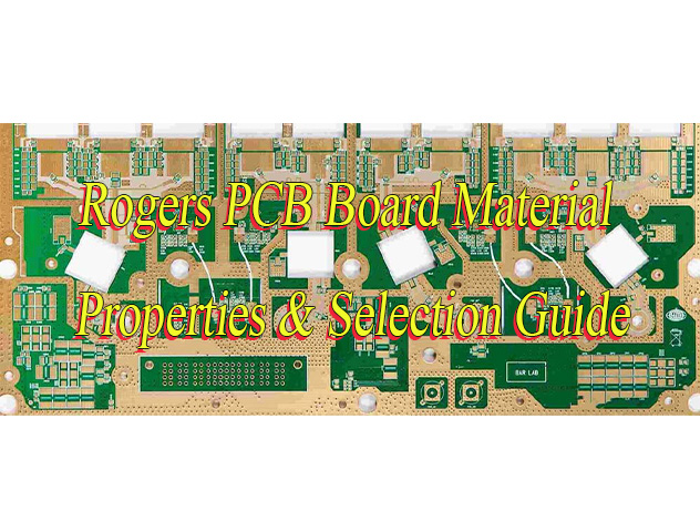
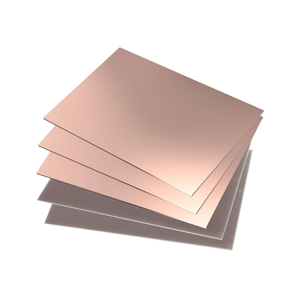
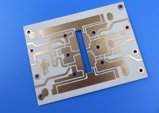
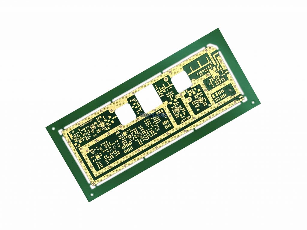
How to choose Rogers PCB board material? Let’s discover properties and datasheet, selection guide, application, cost and material suppliers, alternative material choice for Rogers PCB material.
Are you troubled with these questions?
- Struggling with high-frequency signal loss and distortion?
- Battling deformation and heat dissipation issues under high temperatures, causing unstable performance?
- Facing high costs, low yields, and long lead times for multi-layer PCB processing?
As a Rogers PCB material supplier, EBest Circuit (Best Technology) can provide you service and solutions:
- Low Loss, Stable Signal: Rogers materials deliver ultra-low dielectric loss, ensuring 5G/mmWave signals meet specs in one pass, no more trial-and-error costs.
- Efficient Thermal Management: Proprietary thermal coefficient matching technology resists deformation and accelerates heat dissipation from -40°C to 150°C, extending product life by 30%.
- Hassle-Free Processing: Easy cutting without cracks, paired with exclusive “processing parameter packs” for quick setup, even novices achieve 20% shorter lead times and 15% cost savings.
Welcome to contact us if you have any issues with Rogers PCB board material: sales@bestpcbs.com.
What Is Rogers PCB Board Material?
Rogers PCB Board material is a high-performance substrate developed by Rogers Corporation in the United States specifically for high-frequency electronic circuits. Its core is composed of ceramic-filled polytetrafluoroethylene (PTFE) or hydrocarbon resin, and it has an extremely stable dielectric constant (Dk±0.05) and an ultra-low dissipation factor (Df≤0.003), significantly superior to traditional FR-4 epoxy resin substrates.
It is a key engineering material for addressing signal attenuation and phase distortion issues in scenarios such as 5G communications, millimeter-wave radar, and satellite systems, and is suitable for high-frequency circuit designs above 10GHz.

Rogers PCB Board Material Properties & Datasheet
| Material Model | Dielectric Constant (Dk) | Loss Tangent (Df) | Properties | Applications |
| RO3003™ | 3.00±0.04 | 0.0010@10GHz | Ceramic-filled PTFE, high temperature/frequency stability, eliminates PTFE room-temperature step changes | 77GHz automotive radar, millimeter-wave antennas |
| RO4350B | 3.48±0.05@10GHz | 0.0037@10GHz | FR-4 process compatible, CAF resistant, no special PTFE pretreatment required | 5G base stations, mid/high frequency antennas |
| RT/duroid 5880LZ | 1.96±0.04 | 0.0015@10GHz | Lightweight low-density PTFE composite with special fillers | Aerospace antennas, military radar, missile guidance |
| RT6010.2LM | 10.2±0.25 | 0.0023@10GHz | Ceramic-filled PTFE, high Dk, strict thickness control | Miniaturized power amplifiers |
| TMM10 | 9.2±0.23 | 0.0022@10GHz | Ceramic/hydrocarbon thermoset material, low Dk thermal variation, CTE matched to copper foil | High-reliability striplines |
| TC350™ | 3.5 | 0.002@10GHz | Ceramic filler + glass cloth reinforced PTFE, low CTE, high temperature phase stability | High-power amplifiers, base stations |
| AD250C | 2.55 | 0.0015@10GHz | Glass fiber reinforced PTFE, low PIM performance, high processing yield | Base station antennas, low intermodulation systems |
| RO4450F | 3.37 (prepreg) | 0.0037@2.5GHz | High Tg, supports multiple lamination cycles, FR-4 hybrid compatible | RF hybrid multilayer designs |
| RO3003G2 | 3.00 | Unspecified | VLPED copper foil reduces loss, special fillers enhance microvia density | High-density millimeter-wave circuits |
How to Choose Rogers PCB Board Material?
Rogers PCB Board Material Selection Guide:
1. Precise Matching of Application Scenarios and Core Performance Parameters
- High-Frequency Scenario Selection Logic: 77GHz automotive radar requires RO3003 (Dk=3.00±0.04, Df=0.0010), whose ultra-low loss (0.0010) reduces signal attenuation by over 30% compared to standard FR-4 (Df≈0.015). 5G base station antennas recommend RO4350B (Dk=3.48±0.05, Df=0.0037), achieving insertion loss of 0.5dB/10cm at 28GHz to meet high-speed demands.
- High-Power Scenario Selection Logic: RT/duroid 5880 (Dk=2.20±0.02, Df=0.0009) features thermal conductivity of 1.2W/mK, suitable for millimeter-wave high-power modules like radar transmitters, preventing thermal failure. It improves power density tolerance by 40% versus conventional materials.
- Cost-Effective Scenario Alternatives: RO3010 (Dk=10.2±0.5, Df=0.0025) costs 60% less than RO3003, ideal for consumer electronics like WiFi routers. At 2.4GHz, performance differences are under 5% compared to premium materials, offering high cost efficiency.
2. Process Compatibility and Mass Production Feasibility Verification
- Process Adaptability: RO4000 series is compatible with FR-4 traditional processes but requires diamond drill bits and slow drilling (≤5000rpm) due to ceramic filler brittleness, paired with vacuum dust removal to minimize residue. RT/duroid series containing PTFE needs plasma pretreatment to enhance hole wall roughness, ensuring metallization yield ≥95%.
- Supply Chain Management: Standard lead time for RO4350B is 4–6 weeks; secure 3-month advance stocking with framework agreements. Domestic suppliers like Shengyi Technology offer PPO substrates (Dk=3.2±0.3, Df=0.008) for 70% performance parity with shortened 2-week lead times, suitable for small-to-medium batches.
3. Cost-Performance Balance Strategy
- Hybrid Lamination Technology: Use RO4500 (Dk=3.66±0.05, Df=0.003) for signal layers and FR-4 for inner layers (40% cost reduction). Tested 10-layer boards show impedance deviation ≤±7%, meeting 5G high-frequency needs. RT/duroid 6035HTC (thermal conductivity 2.8W/mK) for power amplifier layers increases cost by 20% while boosting heat dissipation by 50%.
- Domestic Substitute Validation: Huazheng New Materials HF175 (Dk=17.5±0.5, Df=0.009) matches RO3010 loss at 10GHz with 30% lower cost. Certified to AEC-Q200 automotive standards, it suits mid-tier applications like automotive radars.
4. Environmental Adaptability and Long-Term Reliability Assurance
- Wide-Temperature/High-Humidity Scenarios: Rogers materials exhibit moisture absorption <0.1%, outperforming FR-4 (≈0.2%). Electrical performance degradation stays ≤5% under 85℃/85% RH conditions. RO4003C Z-axis CTE=46ppm/℃ aligns with copper foil, withstanding 1000 cycles of -40℃~125℃ thermal shock without delamination, ideal for aerospace reliability.
- Environmental Compliance: RO4000 series meets RoHS/halogen-free standards. Shengyi PPO materials comply with REACH regulations, avoiding EU/North American market entry barriers.
5. Dual Verification System of Simulation and Testing
- Design-Stage Simulation: Use HFSS/CST to model impedance and trace widths; RO4350B simulations align with real-world tests within 3% deviation. 10+ layer boards require TDR validation for interlayer consistency to ensure ±5% impedance control accuracy.
- Testing Validation Standards: Network analyzers measure S-parameters (e.g., S11≤-15dB, S21 insertion loss ≤0.2dB/GHz) alongside thermal imaging for temperature rise ≤20℃. All materials pass three cycles of thermal shock (-55℃~125℃) and 48-hour salt spray tests without corrosion.

When to Use Rogers PCB Material?
Applications of Rogers PCB Material:
- Millimeter-wave radar systems: 77/79 GHz automotive radar (antenna feed network), 24 GHz+ industrial radar (liquid level detection, motion sensing)
- 5G/6G high-frequency communications: millimeter-wave frequency bands (28 GHz, 39 GHz, and future 60 GHz+ base station RF front-end), Massive MIMO antenna arrays (>64-channel phase control)
- Satellite and aerospace electronics: Ka/Ku-band satellite communications (onboard transceiver modules), spacecraft phased array radar (low-orbit satellite payloads)
- Ultra-high-speed digital circuits: 112G PAM4 interfaces (optical modules, data center switches), PCIe 6.0+ signal layers (rates ≥64 GT/s)
- High-precision microwave components: waveguide converters (millimeter waveguide-to-microstrip transition structures), LTCC replacement designs (high-frequency filters, couplers)
- Wi-Fi 6E/7 RF front-end: 6 GHz band power amplifiers and antennas (to mitigate nonlinear distortion)
- Medical microwave equipment: Medical imaging systems (such as MRI radiofrequency coils), tumor radiofrequency ablation electrode control circuits
- High-frequency test equipment: 40GHz+ network analyzer probe cards, terahertz spectrometer sampling heads
- High-power RF equipment: >500W solid-state power amplifiers (thermal conductivity >1W/mK, heat dissipation requirements)

Why Is Rogers Better than FR-4?
Dielectric Loss (Df) & Signal Integrity
- Rogers: Df as low as 0.0037 at 10GHz, ~0.004-0.0045 at 24GHz, with signal loss only 1/3-1/5 of FR-4 in high-frequency scenarios. Supports strong signal integrity in 5G/millimeter-wave applications, e.g., RO4350B achieves ≤0.3dB/cm insertion loss at 26GHz.
- FR-4: Df 0.01-0.02 at low frequencies (<1GHz), rising to 0.02-0.03 at 10GHz+. 10GHz signal insertion loss increases by 1.2dB/inch, prone to heating-induced performance degradation. Limited to low-frequency (<1GHz) applications.
Dielectric Constant (Dk) Stability & Impedance Control
- Rogers: Tight Dk tolerance ±2% with high frequency/temperature stability, e.g., RO4350B maintains Dk 3.48±0.05 at 10GHz and 3.44±0.02 at 24GHz. Enables precise impedance matching (±2% tolerance for 5G/automotive radar) and minimizes crosstalk/reflection.
- FR-4: Dk variation >±5%, shifting significantly with frequency (e.g., Dk rises to 4.6-4.8 at 10GHz). High-frequency impedance control becomes challenging, often exceeding ±8% deviation and causing signal distortion.
Moisture Absorption & Dimensional Stability
- Rogers: Moisture absorption <0.1%, with minimal Dk/Df changes in humid environments (e.g., RT6002 exhibits negligible Dk variation from -55°C to 150°C). Dimensional stability matches copper foil CTE, preventing delamination/warpage.
- FR-4: Moisture absorption 0.1%-0.2%, leading to 5-10% Dk increase and 15-20% Df degradation. Under 85°C/85% RH, copper contact resistance rises 8-12% within 48 hours, risking circuit performance drift.
Thermal Performance & High-Temperature Resistance
- Rogers: Thermal conductivity 0.6-2.0 W/m·K (e.g., 92ML reaches 2.0 W/m·K), 2-8× higher than FR-4 for superior heat dissipation. Tg >280°C, suitable for high-temperature soldering/power applications, e.g., RO3003G2 withstands -269°C to 260°C and 0.5dB loss at 77GHz over 5cm.
- FR-4: Thermal conductivity 0.3-0.4 W/m·K, poor heat dissipation. Tg 130-180°C, prone to delamination/warpage at high temperatures (e.g., phase error exceedance in 125°C automotive engine compartments).
High-Frequency/Microwave Performance
- Rogers: Low loss in millimeter-wave radar (77GHz), satellite comms, etc., with minimal signal delay and high gain. RO5880 achieves 0.0009 loss at 26GHz and ≤1° phase error, meeting ISO 26262 ASIL B for automotive safety.
- FR-4: High loss at high frequencies, significant signal distortion at 10GHz+. Suitable only for low-frequency RF devices (e.g., Bluetooth/Wi-Fi at 2.4GHz), with elevated risk in 5G high-frequency scenarios.
Mechanical Strength & Processing Adaptability
- Rogers: High mechanical strength and bending resistance. Supports thin boards (8mil) and high-layer-count designs. Compatible with LoPro copper foil (0.4μm surface roughness), reducing conductor loss by 40%. Ideal for precision circuits/outdoor equipment.
- FR-4: Prone to warpage/delamination in thin-board or high-frequency applications. Processing limitations include 1.2dB/inch insertion loss increase at 10GHz under 95% RH for HDI boards, requiring design margin compensation.
Environmental Adaptability & Reliability
- Rogers: Salt spray resistant (96h no corrosion), alcohol resistant (1000 cycles no performance change). Complies with medical/automotive safety standards, e.g., medical RF ablation devices maintain 1.5% impedance deviation after 1000 alcohol disinfections.
- FR-4: High risk of oxidation/corrosion in humid/high-temperature environments. Prone to CAF (copper ion migration), requiring vacuum packaging and moisture-proof designs for long-term reliability.
Cost & Application Suitability
- Rogers: Higher unit cost, but cost-performance balance achieved via hybrid presses (e.g., high-speed signal layers on Rogers, other layers on FR-4). Ideal for high-demand scenarios like 5G/automotive electronics.
- FR-4: Lower cost, good mechanical properties, and ease of processing. Suitable for low-to-mid frequency RF applications and cost-sensitive projects (e.g., general digital circuits, low-speed signal scenarios).

How Much Does Rogers PCB Board Material?
| Material Model | Thickness (mm) | Copper Thickness (oz) | Single Sheet Price (610×508mm) | Bulk Price (100 Sheets) |
| RO4350B | 0.51 | 1 | $228 | $197/sheet |
| RO4350B | 0.81 | 1 | $318 | $282/sheet |
| RO3003™ | 0.13 | 0.5 | $495 | $428/sheet |
| RO3003™ | 0.25 | 1 | $680 | $590/sheet |
| RT/duroid 5880LZ | 0.51 | 0.5 | $1,150 | $980/sheet |
| TMM10 | 0.76 | 1 | $890 | $760/sheet |
| RO4450F (Prepreg) | 0.10 | N/A | $85/㎡ | $72/㎡ |
Common Rogers PCB Material Suppliers
| Manufacturer | Representative Series | Technical Advantages | Price Range | Key Customer Cases |
| Rogers | RO3000®, RT/duroid® | Lowest Df for millimeter wave (0.0009@10GHz) | $250-600/m² | Tesla 77GHz Radar, SpaceX Starlink |
| DuPont | TLY™, TAC™ | Space-grade temperature stability (ΔDk<0.02) | $400-800/m² | Boeing Satellite Payloads, Raytheon Missile Systems |
| Panasonic | Megtron®6/7/8 | Ultra-low crosstalk for 112Gbps | $180-350/m² | Cisco 800G Switch, Apple Server |
| Isola | Tachyon®/Astra® | Cost-effective high-frequency solution (Df=0.0035) | $150-280/m² | Samsung 5G RRU, Broadcom PHY Chip |
| Mitsubishi | CLTE™-AT | High Tg (180℃) thermal resistance | $220-380/m² | Huawei Base Station PA, Siemens Industrial Radar |
Alternatives to Rogers High Frequency PCB Material
Taconic High-Frequency Materials
- Advantages: Low dielectric constant (Dk) and low loss factor (Df) ensure high-frequency signal transmission integrity; excellent dimensional stability and chemical resistance for extreme environments; superior processability for precise control of trace width and spacing, enhancing signal integrity.
- Application: Ku-band radar, satellite communication terminals, military aerospace electronics, automotive radar (77GHz/24GHz), 5G millimeter-wave infrastructure.
- Price & Cost: Positioned in the high-end market, cost is slightly higher than traditional FR-4 but lower than Rogers counterparts, offering significant cost-effectiveness.
- Lead Time: Conventional models have a lead time of approximately 7-18 days; customized products require negotiation based on order volume and process complexity.
Arlon High-Frequency Materials
- Advantages: High thermal conductivity (e.g., CLTE/TC series reaches 2-3.5W/M*K) for high-power RF signal heat dissipation; low-loss characteristics suitable for high-frequency circuits; complementary technology to Rogers, enhancing material system completeness.
- Application: Automotive LED driver modules, new energy vehicle power systems, radar radomes, high-frequency equipment substrates, aerospace electronics.
- Price & Cost: Economical solutions outperform Rogers RO3000 series in cost; high-end models (e.g., PTFE-based substrates) are priced higher due to process complexity.
- Lead Time: Standard inventory products have a 5-16 day lead time; special specifications require over 12 weeks, dependent on supply chain coordination.
Isola High-Frequency Materials
- Advantages: Models like FR408HR maintain loss differential within 7% at 1GHz frequency, saving costs by up to 54%; compatible with traditional FR-4 processing techniques, lowering production barriers.
- Application Scenarios: 5G base stations, high-speed digital circuits, automotive electronic control units, high-frequency communication modules.
- Price & Cost: Approximately 600 yuan per square meter, significantly lower than Rogers RO4350B (1,300 yuan/square meter), ideal for cost-sensitive commercial projects.
- Lead Time: Conventional bulk orders have a 7-10 day lead time; urgent orders can be shortened to 3-5 days with prior confirmation of inventory and capacity.
Panasonic High-Frequency Materials
- Advantages: High thermal conductivity and low-loss traits meet automotive-grade high-temperature requirements; exceptional material stability with temperature deviation controlled within ±0.25%; compatible with advanced packaging processes.
- Application Scenarios: On-board radar systems, ADAS sensors, industrial automation controls, high-frequency communication equipment.
- Price & Cost: Positioned in mid-to-high-end markets, cost is comparable to Rogers RO3000 series but offers higher thermal conductivity options.
- Lead Time: Conventional models have a 12-week lead time; bulk orders can be negotiated to 8-10 weeks, considering production scheduling and logistics.
Welcome to contact us if you have any issues with high frequency PCB material: sales@bestpcbs.com.
Tags: Rogers PCB Board Material, Rogers PCB Material Properties


