





A laser microvia can look centred at its entry while its bottom opening is too close to the edge of the buried target pad. Check the entry and landing separately. A top-side image cannot show the hidden margin or establish that the finished interface is sound.
What the Target Pad Does
The target pad is the copper feature at the bottom of the microvia. It provides the intended landing on the destination layer. An IPC-hosted paper on microvia failure modes distinguishes misalignment at the capture and target pads.
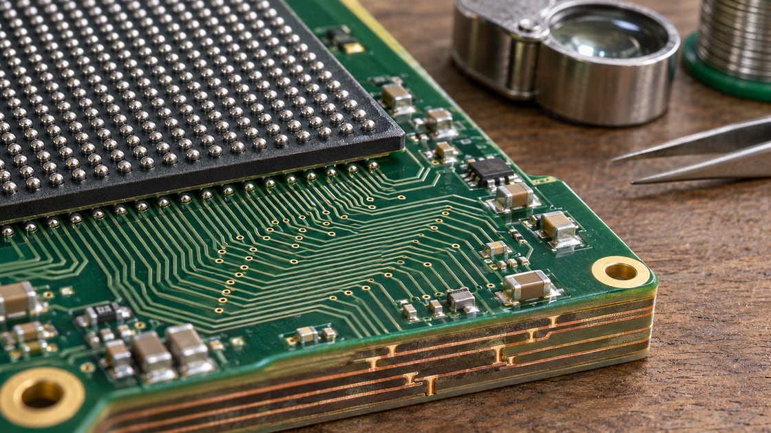
Why Top and Bottom Can Tell Different Stories
The entry relates to the outer pad. The bottom relates to another layer and the effective hole geometry at that depth. A centred entry alone does not locate the buried copper relative to the hole bottom.
Detailed Parameters for a Landing Check
| Parameter | Unit or record | Purpose |
| — | — | — |
| Finished target diameter | µm | Defines the circular example pad |
| Bottom opening diameter | µm | Defines the footprint at the landing |
| Relative centre offset | µm | Describes target registration |
| Required remaining margin | µm | Sets the acceptance boundary |
| Layer pair and via type | Drawing IDs | Identifies which construction is being checked |
Capture Pad vs Target Pad
| Question | Capture pad | Target pad |
| — | — | — |
| Where is it? | At the via entry | On the destination layer |
| Which diameter applies? | Entry opening | Bottom opening |
| What should be verified? | Registration to outer land | Landing overlap and interface |
Worked Example: Budget the Remaining Margin
For hypothetical round features, use half the difference between target diameter and bottom opening, minus the offset magnitude. With a 180 µm target, 90 µm bottom opening and 25 µm offset, the remaining margin is 20 µm. If the agreed limit were 25 µm, this example would fail. The values are not a supplier capability.
Use Compatible Worst-Case Inputs
For a conservative circular estimate, use the minimum target diameter and maximum relevant bottom opening and offset under the agreed model. Do not count a tolerance twice. If the fabricator uses a different statistical or geometric approach, document it separately.
Do Not Reuse the Circular Formula for Every Pad
A shaped pad, neighbouring cutout or noncircular opening can put the closest edge in a different direction. Check the real shapes and the approved datum. Use the simple calculation only where its assumptions describe the feature.
Separate Misregistration From Interface Damage
A sufficient geometric margin does not show that the interface is clean, continuous or properly plated. The IPC-hosted drilling paper describes difficulties that can occur when the laser misses its intended landing. Check geometry and interface condition as separate observations.
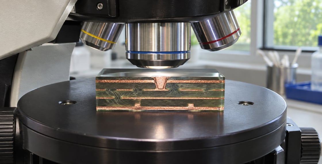
Ask What the Cross-Section Represents
A section can expose the hidden interface, but its cut plane limits what it shows. A section aligned with one direction may miss a displacement in another direction. Agree on a representative inspection plan rather than using one attractive image as proof of the worst case.
Treat Stacked Structures Individually
In a stack, the landing for one step is not automatically the landing for the next. Check the layer pair, process sequence and relevant interfaces. Do not assume a result on a single blind via covers a different stacked construction.
Connect the Margin to the Routing Trade-Off
Increasing the target pad can consume escape-routing space or change clearance. Before changing it, compare the proposed opening, stackup and registration with the fabricator. The BestPCBs via types guide covers the wider interconnect choices.
Put the Review on the Release Drawing
Record layer pairs, the intended landing geometry, accepted criteria and inspection evidence. Keep the drawing and coupon identifiers linked. When the proposed build differs from the approved geometry, resolve the discrepancy before relying on the calculation.
Request an HDI Review
Share the stackup and via geometry with Best Technology.
FAQ
Are capture pad and target pad the same thing?
They refer to different positions in this article: the entry pad and the destination pad. Terminology can vary, so name the exact layer and show the geometry in the drawing. That makes the requested check clear even when a supplier uses different naming.
Can the entry diameter be used for the bottom calculation?
Only if it actually represents the specified bottom opening, which cannot be assumed for a tapered via. Use the geometry at the target interface for the landing check. Keep the entry calculation separate and confirm how the fabricator defines and measures each opening.
Does a centred top view prove adequate landing?
No. It shows the relationship visible at the surface and does not identify the buried target location. The bottom opening and the target pad belong to another check. Ask for suitable design and inspection evidence if the hidden margin is important for approval.
Can I fix the issue by increasing every target pad?
A larger pad can improve the nominal geometric margin but may reduce routing space or clearance. Review the actual offset and manufacturing proposal first. Change the specific geometry that needs it and confirm that the revised construction still meets electrical and layout constraints.
Is positive margin enough for acceptance?
Not necessarily. The drawing can require more than simple overlap, and the result depends on how the dimensions were defined. Compare the calculated or measured margin with the actual requirement and verify the interface condition separately before treating the via as accepted.
What if the section is cut at the wrong angle?
The observed geometry may not show the true offset direction or the narrowest remaining margin. Document the cut and ask how the sample was prepared. If the result controls disposition, use the inspection plan to determine whether another view or suitable evidence is needed.
Does electrical continuity catch every landing problem?
Continuity shows a path exists under the test conditions. It does not measure the remaining target margin or rule out all structural weaknesses. Use electrical and physical evidence for their intended purposes, and apply the acceptance rules for the specific HDI build.
What should the fabricator review before ordering?
Send the layer pair, target and entry pads, expected opening geometry and clearance requirements. Ask how registration is budgeted and what evidence represents the actual production structure. Keep the approved interpretation tied to the released stackup and artwork so later changes can be assessed.
You may also like


Tags: capture pad, HDI registration, laser via, microvia target pad