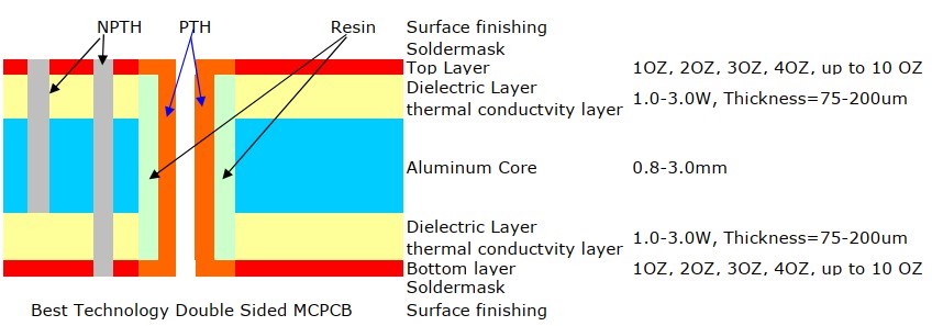
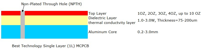
A simple layer single sided MCPCB consists of a metal base (usually aluminum, or copper alloy), Dielectric (non-conducting) Layer, Copper Circuit Layer, IC components and solder mask.
The prepreg dielectric provides excellent heat transfer from the foil and components to the base plate, while maintaining excellent electrical isolation. The base aluminum/copper plate gives the single-sided substrate mechanical integrity, and distributes and transfers the heat to a heat sink, mounting surface or directly to the ambient air.
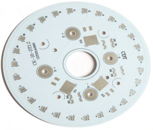
The Single-Layer MCPCB can be used with surface mount and chip & wire components, and provides much lower thermal resistance than FR4 PWB. The metal core provides lower cost than ceramic substrates, and allows much larger areas than ceramic substrates.
Single Layer MCPCB Capability
- Base material: Aluminum/Copper/Iron Alloy
- Thermal Conductivity (dielectrial layer): 0.8, 1.0, 1.5, 2.0, 3.0 W/m.K.
- Board Thickness: 0.5mm~3.0mm(0.02″~0.12″)
- Copper thickness: 0.5 OZ, 1.0 OZ, 2.0 OZ, 3.0 OZ, up to 10 OZ
- Outline: Routing, punching, V-Cut
- Soldermask: White/Black/Blue/Green/Red Oil
- Legend/Silkscreen Color: Black/White
- Surface finishing: Immersion Gold, HASL, OSP
- Max Panel size: 600*500mm(23.62″*19.68″)
- Packing: Vacuum/Plastic bag
- Samples L/T: 4~6 Days
- MP L/T: 5~7 Days
Single Layer MCPCB FAQs
1. What is a single layer MCPCB?
A single layer MCPCB consists of a metal base (typically aluminum or copper), a non-conductive dielectric layer, and a copper circuit layer. Unlike standard PCBs, the metal core acts as a primary heat sink, moving thermal energy away from high-power components to the environment or an external cooling system.
2. How does a single layer MCPCB differ from a standard FR4 PCB?
The primary difference is the substrate material. While FR4 uses fiberglass and epoxy, an MCPCB uses a metal base. This allows MCPCBs to have significantly higher thermal conductivity. While a standard FR4 board typically has a conductivity of around 0.25 W/mK, a single layer MCPCB can range from 1.0 W/mK to 9.0 W/mK depending on the dielectric material used.
3. What are the typical applications for single layer MCPCBs?
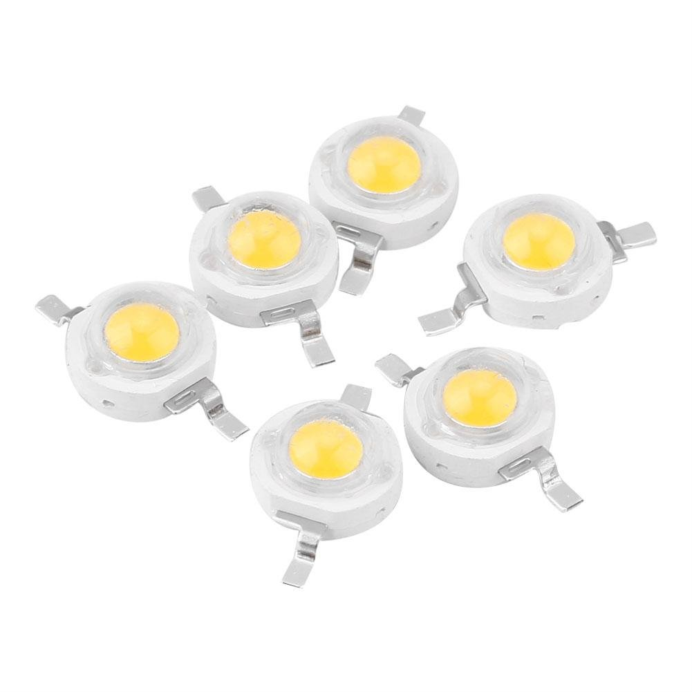
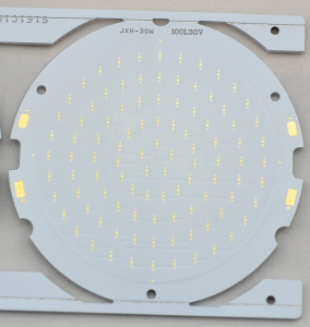
Single layer MCPCBs are most commonly used in the LED lighting industry (street lights, automotive headlamps, and backlight units) because LEDs generate significant heat that can degrade performance if not dissipated. They are also widely used in power conversion, solid-state relays, and the automotive sector for motor control modules.
4. Can you have plated through-holes (PTH) on a single layer MCPCB?
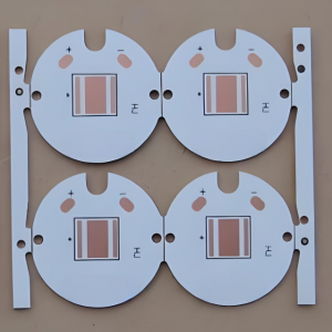
Generally, no. In a standard single layer MCPCB, the metal base is conductive, so through-holes would cause a short circuit between the signal layer and the base. Components are typically Surface Mount Devices (SMD). If through-hole components are required, specialized “COB” (Chip on Board) or complex insulated hole processes are needed, which significantly increases cost.
5. What are the layers of a single layer MCPCB?
A standard stack-up includes four main layers:
- Solder Mask: Protects the copper circuit.
- Circuit Layer: The copper foil used for traces.
- Dielectric Layer: The most critical part; it provides electrical insulation while facilitating heat transfer.
- Metal Substrate: Usually 1.0mm to 3.2mm of Aluminum (5052 or 6061) or Copper.
6. Is aluminum or copper better for the metal core?
Aluminum is the most popular choice because it is cost-effective and provides excellent thermal dissipation for most applications. Copper offers even higher thermal conductivity but is much heavier and more expensive. Copper is usually reserved for extremely high-power density applications where aluminum’s performance is insufficient.